
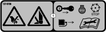
 , which means Caution, Warning,
or Danger—personal safety instruction. Failure to comply with
these instructions may result in personal injury or death.
, which means Caution, Warning,
or Danger—personal safety instruction. Failure to comply with
these instructions may result in personal injury or death.
Maintenance
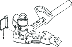
Using the Kickstand When Tipping the Cutting Unit
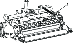
Note: Whenever the verticutter has to be tipped to expose the verticutter blades, use the kickstand (supplied with traction unit) (Figure 15).
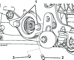
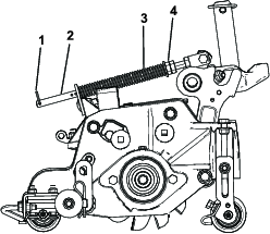
Lubricating the Verticutter
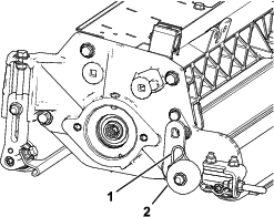
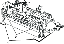
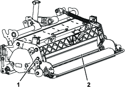
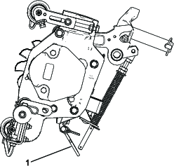
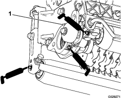
Each verticutter has 5 grease fittings (Figure 16) that must be lubricated weekly with No. 2 lithium grease.
The lubrication points are the front roller (2), the rear roller (2), and the reel motor splines (1).
Important: Lubricating the cutting units immediately after washing helps purge water out of the bearings and increases bearing life.
-
Wipe each grease fitting with a clean rag.
-
Apply grease until you see clean grease coming out of the roller seals and the bearing relief valve (Figure 16).
-
Wipe any excess grease away.
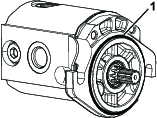
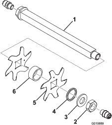
Removing the Verticutter Blades from the Shaft
-
Secure the end of the verticutter shaft, which has only one washer and nut, in a vise.
-
On other end of shaft, rotate the nut counter-clockwise and remove the nut.
Caution
The blades are extremely sharp and may have burrs that will cut your hands.
Use caution when removing the blades from the shaft.
-
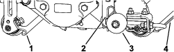
Remove the small spacer, the washer, the blades and the large spacers. Clean and lubricate the square shaft with a light coating of grease to simplify the assembly (Figure 17).
Important: Do not invert the verticutter reel blades. The order of disassembly is extremely important. Do not invert the verticutter reel blades when disassembling or reverse the order when assembling them. Note the verticutter blades index hole. The index hole is provided for assembly in order to obtain the proper helix for the verticutter reel.
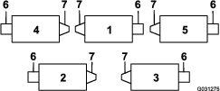
Installing the Verticutter Blades
-
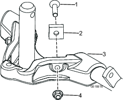
Assemble a reel blade (Figure 18).
-
Assemble a large spacer.
-
Do not invert the reel blades when assembling them onto the reel shaft.
Note: If the blades are inverted, the blades that are in use (rounded) will mix with the sharp ends of the previously unused blades; this will cause unsatisfactory verticutter performance.
-
Install the next blade clockwise so that the index reference hole (Figure 18) is not aligned with the first blade hole by one flat of the shaft.

-
Continue to install spacers and blades in this manner until the full complement of blades has been installed.
Note: When properly assembled, the blades will be staggered in such a manner as to appear like a helix.
-
Install the small spacer to the shaft.
-
Apply Blue Loctite 242 to the nut. Install the nut onto the shaft (machined side of the nut toward the spacer) and tighten it to 109 to 135 N∙m (80 to 100 ft-lb).
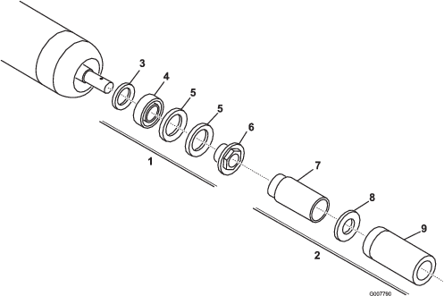
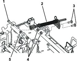
Servicing the Roller
The Roller Rebuild Kit (Part No. 114-5430) and the Roller Rebuild Tool Kit (Part No. 115-0803) (Figure 19) are available for servicing the roller. The Roller Rebuild Kit includes all the bearings, bearing nuts, inner seals, and outer seals to rebuild a roller. The Roller Rebuild Tool Kit includes all the tools and the installation instructions required to rebuild a roller with the roller rebuild kit. Refer to your parts catalog or contact your authorized Toro distributor for assistance.