Refer to the following table for the appropriate kit, traction unit, and traction-unit serial number combination:
| Kit Model Number | Traction Unit Model Number | Serial Number |
| 02945 | 02750 (T4240) | 405398421 and above |
| 30654 (CT2240) | 405623665 and above | |
| 31654 (CT2240) | All serial numbers | |
| 30657 (LT3340—cab equipped) | 405006390 and above | |
| 02946 | 30657 (LT3340) | 405006390 and above |
| 30659 (LT-F3000) | 404879018 and above | |
| 02947 | 30659 (LT-F3000—cab equipped) | 404879018 and above |
| 02949 | 02750 (T4240—cab equipped) | 405398421 and above |
| 02950 | 31050TE (PLH800) | 320000155 and above |
Safety
Safety and Instructional Decals
 |
Safety decals and instructions are easily visible to the operator and are located near any area of potential danger. Replace any decal that is damaged or missing. |
Installation
Preparing the Machine
-
Park the machine on a level surface.
-
Engage the parking brake.
-
Lower the cutting unit(s).
-
Shut off the machine and remove the key.
Installing the Kit
Parts needed for this procedure:
| Slope sensor | 1 |
| Slope-sensor mount (LTF/LT/CT only) | 1 |
| Slope-sensor mount (T4240 only) | 1 |
| Bolt (M6 x 35 mm) | 2 |
| Bolt (M6 x 25 mm—LTF/LT/CT only) | 2 |
| Flange nut (M6) | 4 |
| Bolt (M10—T4240 only) | 2 |
| Flange nut (M10—T4240 only) | 2 |
| LED indicator | 1 |
| Alarm | 1 |
| Wire harness | 1 |
| Cable tie | 6 |
| Slope sensor decal | 1 |
Installing the Kit
-
Release the operator platform; refer to your machine Operator’s Manual.
-
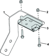
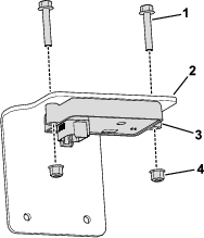
Use 2 bolts (M6 x 35 mm) and 2 flange nuts (M6) to secure the slope sensor to the slope-sensor mount.
-
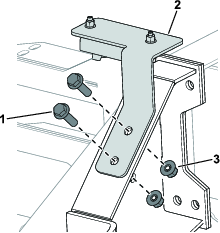
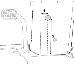
Use 2 bolts (M6 x 25 mm) and 2 flange nuts (M6) to secure the slope sensor mount to the chassis (Figure 3).
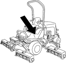
Note: Figure 2 shows the location of the chassis with the operator’s platform in the secured position. The chassis mounting position is under the operator’s platform.
-
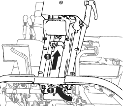
Install the wire harness connector labeled P02 to the slope sensor (Figure 4).
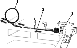
-
Route the wire harness towards the control panel (Figure 4) and ensure that it is secured and away from moving parts or pinch points.
-
Coil any additional amount of wire harness to the left of the control panel (Figure 4).
-
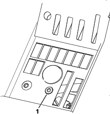
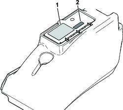
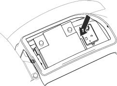
Remove the plug and install the LED light in the control panel as shown in Figure 5.
-
Connect the remaining wire-harness connectors as follows:
-
Wire harness connector labeled P01: Connect to one of the 6-pin sealed connectors located on the main harness below the control panel.
-
Wire harness connector labeled P08: Connect to the LED light.
-
Wire harness connector labeled P09: Connect to the alarm and position the alarm under the control panel.
Note: Ensure that the alarm does not obstruct any controls.
-
-
Secure the operator’s platform; refer to your machine Operator’s Manual.
-
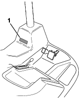
Install the slope-sensor decal adjacent to the machine-stability decal on the operator’s platform (Figure 6).
Installing the Kit
-
Remove the 6 screws securing the control panel to the control pod (Figure 7).
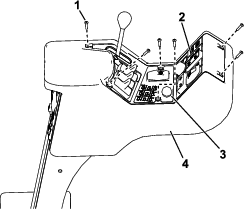
-
Carefully lift off the panel, ensuring that the connectors to the existing switches are not disturbed.
-
Remove the plug (Figure 7) from the console.
-
Insert the LED light into the console.
-
Install the wire harness as shown in Figure 8.
-
Connect the LED light to the wire-harness connector labeled P08 (Figure 8).
-
Connect the alarm to the wire-harness connector labeled P09 (Figure 8).
-
Route the remaining end of the wire harness down the control arm (Figure 8).
-
Use the previously-removed screws to secure the control panel to the control pod.
-
Raise the hood.
-
Route the wire harness along the machine chassis and up to the electrical panel.
-
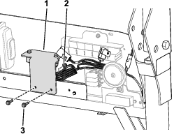
Use 2 bolts (M6 x 35 mm) and 2 flange nuts (M6) to secure the slope sensor to the slope-sensor mount (Figure 9).
-
Connect the wire-harness connector labeled P02 to the slope sensor.
-
Use 2 bolts (M6 x 25 mm) and 2 flange nuts (M6) to secure the slope sensor mount to the electrical panel (Figure 10).
-
Connect the kit-wire-harness connector labeled P01 to one of the 6-pin sealed connectors located below the relays on the electrical panel.
-
Use cable ties to secure the wire harness away from moving parts or pinch points.
-
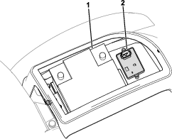
Install the slope-sensor decal adjacent to the machine-stability decal on the storage-pod lid (Figure 11).
Installing the Kit
-
Remove the battery cover; refer to the electrical system maintenance section of your Operator’s Manual.
-
Use 2 bolts (M6 x 35 mm) and 2 flange nuts (M6) to secure the slope sensor on the mounting plate in front of the battery (Figure 12).
-
Remove the steering wheel, dashboard, and front panel (Figure 13).
Note: Carefully lift off the dashboard, ensuring that the connectors to the existing switches are not disturbed.
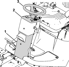
-
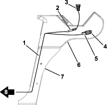
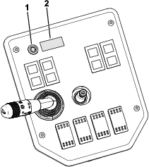
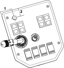
Remove the plug and install the LED light and the slope-sensor decal to the dashboard (Figure 14).
If a hole for the LED light is not present, drill a 19-mm hole in the location shown in Figure 15..
-
Remove the plug and install the alarm on the steering-column rear panel (Figure 16).
If a hole for the alarm is not present, drill a 30-mm hole in the location shown in Figure 17.

-
Connect the wire harness as follows:
-
Wire harness connector labeled P01: Connect to one of the 6-pin sealed connectors located on the main harness next to the grass chute on the right side of the machine.
-
Wire harness connector labeled P02: Connect to the slope sensor.
-
-
Route the wire harness under the platform with the machine wire harness and into the steering column (Figure 18).
-
Connect the remaining wire-harness connectors as follows:
-
Wire harness connector labeled P08: Connect to the LED light.
-
Wire harness connector labeled P09: Connect to the alarm.
-
-
Use a cable tie to coil together any additional amount of wire harness in front of the battery (Figure 19).
-
Use cable ties to secure the wire harness away from moving parts and pinch points.
-
Install the battery cover and the dashboard, steering wheel, and front cover.
Calibrating the Sensor
-
While the machine is on a flat surface, remove the plug from calibration connectors (labeled P05 and P06).
-
Plug the connectors together.
-
Turn the ignition key to the ON position, but do not start the engine.
Note: The LED light blinks as the sensor calibrates.
-
When the light no longer blinks, turn the ignition key to the OFF position.
-
Disconnect the calibration connectors and install the plug onto the connectors.
Operation
Using the Slope Sensor
When you start the machine, the LED light illuminates for 5 seconds to indicate that the sensor is functioning properly.
The light and alarm indicates the severity of the slope:
-
No light—normal operating conditions
-
Slow, flashing light—moderate slope
-
Fast, flashing light and audible alarm—steep slope; proceed to a more shallow slope.
Warning
Slopes are a major factor related to loss-of-control and tip-over accidents, which can result in severe injury or death.
Use extreme caution when operating the machine on a slope.