
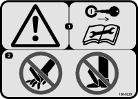
 , which means Caution, Warning,
or Danger—personal safety instruction. Failure to comply with
these instructions may result in personal injury or death.
, which means Caution, Warning,
or Danger—personal safety instruction. Failure to comply with
these instructions may result in personal injury or death.


Maintenance
Caution
If you leave the key in the switch, someone could accidently start the engine and seriously injure you or other bystanders.
Remove the key from the switch before you perform any maintenance.
Recommended Maintenance Schedule(s)
| Maintenance Service Interval | Maintenance Procedure |
|---|---|
| Before each use or daily |
|
| Every 40 hours |
|
| Every 100 hours |
|
Lubrication
Chassis Maintenance
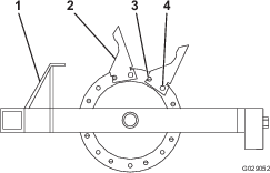
Checking Tire Air Pressure
| Maintenance Service Interval | Maintenance Procedure |
|---|---|
| Before each use or daily |
|
-
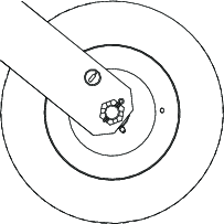
Check the tire pressure (Figure 27).
You should measure 413 kPa (60 psi).
-
If needed, add or remove air to or air from the tires until you measure 413 kPa (60 psi).
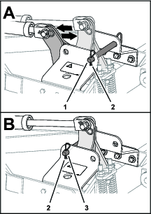
Checking the Main Arms Bushings
| Maintenance Service Interval | Maintenance Procedure |
|---|---|
| Every 100 hours |
|
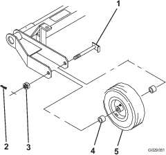
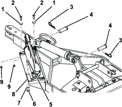
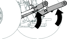
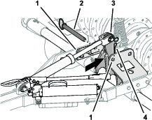
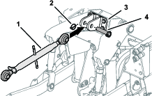
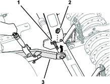
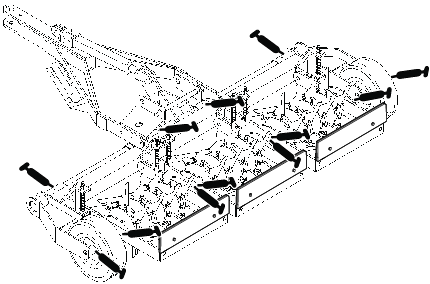
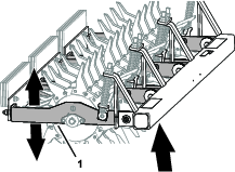
The 6 main arms pivot freely horizontally and vertically to allow the unit to follow the contour of the ground. A bronze bushing is pressed inside the pivot holes between the main arms and frame mounting brackets (Figure 28).
-
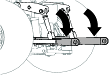
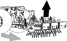
Move the aerator to the transport position; refer to Using the Aerator.
-
Check that the 6 main arms pivot freely (Figure 28).
-
If a main arm binds, perform the following steps:
-
Loosen the spring tension; refer to Adjusting the Springs.
-
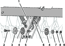
Remove the bolt, nut, washers, and bushing, that secure the main arm to the frame mounting bracket (Figure 28) and check the hardware for wear.
Note: Replace all worn or damaged hardware. The bronze bushing is 3 mm (1/8 inch) longer than the combined main arm and mounting bracket plate thickness.
-
Assemble the main arm to the frame mounting bracket with the bolt, nut, washers, and bushing (Figure 28).
-
Tighten the bolt (5/8 x 2 inch) and nut (5/8 inch) against the bushings, not the arms, to allow it to pivot freely.
-
Adjust the spring tension; refer to Adjusting the Springs.
-
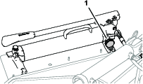
Adjusting the Springs
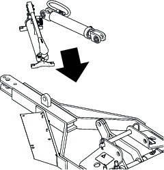
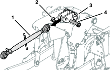
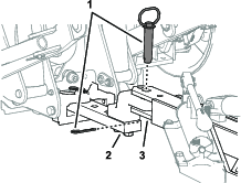
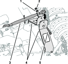
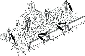
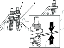
The purpose of the springs is to distribute the weight evenly and reduce the shock load on the pivot points. Adjust the springs evenly across to level the machine. Use the nuts at top of the spring rod to adjust the spring tension (Figure 29).
Important: When adjusting the spring tension, do not completely compress the coils. Allow at least 1.6 mm (1/16 inch) of space between coils.
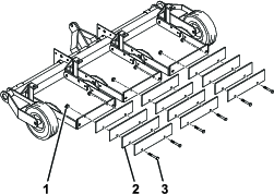
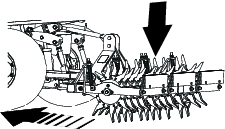
Checking the Tines
| Maintenance Service Interval | Maintenance Procedure |
|---|---|
| Before each use or daily |
|
To obtain maximum aerating performance, always check the tines for wear and damage before every use. Severely worn tines are easy to bend or break and leave the cores in the ground. See Figure 30 for examples of tine wear.
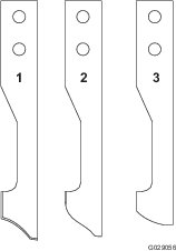
Always clean cores out of the tines before storage. Cores left in tines for extended periods can cause pitting on the inside of the tine which keep the core from ejecting.