Installation
Preparing the Machine
-
Park the machine on a level surface.
-
Engage the parking brake.
-
Shut off the engine and remove the key.

Installing the Four-Post Rollover Protection System (ROPS)
Parts needed for this procedure:
| Left ROPS post | 1 |
| Right ROPS post | 1 |
| Crossbar | 1 |
| Floor support | 2 |
| Flange-head bolt (1/2 x 3-1/2 inches) | 4 |
| Flange-head bolt (3/8 x 2-1/2 inches) | 4 |
| Flange-head bolt (3/8 x 1 inch) | 4 |
| Flange-head bolt (1/2 x 1-1/4 inches) | 2 |
| Locknut (3/8 inch) | 8 |
| Locknut (1/2 inch) | 6 |
-
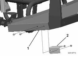
Install the floor supports (1 on each side of the machine) under the floor using 4 flange-head bolts (3/8 x 1 inch) and 4 locknuts (3/8 inch) as shown in Figure 2.
-
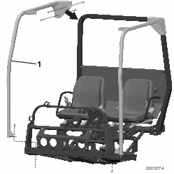
Install each ROPS post over the corners of the ROPS bar and loosely secure them to the floor and floor support using 2 flange-head bolts (1/2 x 1-1/4 inches) and 2 locknuts (1/2 inch) as shown in Figure 3.
-
Loosely secure the ROPS posts to the roll bar using 4 flange-head bolts (1/2 x 3-1/2 inches) and 4 locknuts (1/2 inch) as shown in Figure 3.
-
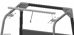
Loosely install the crossbar between the ROPS posts using 4 flange-head bolts (3/8 x 2-1/2 inches) and 4 locknuts (3/8 inch) as shown in Figure 4.
-
Torque the locknuts (3/8 inch) to 37 to 45 N∙m (27 to 33 ft-lb).
-
Torque the locknuts (1/2 inch) to 91 to 113 N∙m (67 to 83 ft-lb).