Contact Toro NSN at 1-844-GEOLINK (1-844-436-5465) or GeoLinkNSN@toro.com for customer service.
Note: The display is in STANDARD MODE after startup. To change modes, refer to the GeoLink Operator’s Manual.
Note: Use the ignition key of the machine to run or shut off the display, receiver, and section controller.
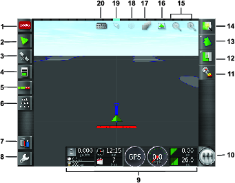
Using the Touch Screen
Sprayer information displays on the screen when you touch and enable the individual icons.
-
Press any icon on the screen to display what is shown on the screen.
-
Press on an icon to select a function, and the related options display.
-
Press the options as required, and press the green check box icon for the new display.

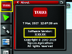
Identifying the Software Version
Press the Toro icon at the top, left corner of the screen to display the software version.
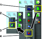
Using Quick Start
Press the quick-start icon (Figure 2) and a wizard walks you through the steps in this guide.
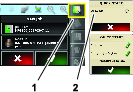
Creating a Field
Note: Create a separate field for each property. Each field can contain multiple boundaries.
-
Press the field-menu icon.
-
Press the new-field icon.
-
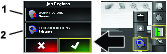
Press the field name icon, type in the field name, and press the green check box icon (Figure 5).
Creating a New Field Boundary
Note: The boundary is created at the outside, center of the front, left tire.
-
Drive to the field area of the job site.
-
Press the field-menu icon.
-
Press the record-field boundary icon.
-
Drive the machine around the perimeter of the boundary.
-
When you are close to the beginning of the boundary perimeter, press the complete boundary icon.
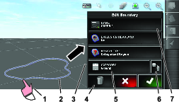
Naming and Categorizing a Field Boundary
Note: The boundaries that you create and save are accurate and repeatable only if the boundary is created using RTK correction.
-
After creating a boundary, hold your finger on the boundary line.
-
When the boundary line is highlighted, remove your finger from the screen and the edit boundary menu opens.
-
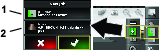
Press the name icon, type in the boundary name, and press the green check box icon.
-
Press the region type icon, and select a categorized region, work region, exclude region, or disabled.
-
Press the category icon and select a preset category or create a new category.
-
Press the green check box icon
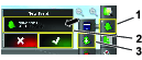
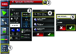
Creating a Product and Tank Volume
Note: Ensure that the units are correct for your use; refer to Selecting the Correct Units of Measure in the GeoLink Operator’s Manual.
-
Fill the sprayer tank with clean water.
-
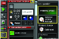
Press the sprayer-rate controller icon and expand the rate controller mini view (Figure 9).
-
Press the select product icon.
-
In the pop-up window, press the product name icon, and select a programmed product or a new product.
-
Pressing the new product and green check box icons begin the new product setup wizard.
-
In the new product setup window, press the custom product and right arrow icons.
-
Press product name icon, type the new product name with the pop-up keyboard window, press the green check box icon and then the right arrow icon.
-
Press the rate increments icon, type amount that you want to increment the application rate, and press the green check box icon.
-
Press the product rate 1 or 2 icons, type application rate for the product, and press the green check box icon and then the right arrow icon.
-
In the save product setting pop-up window, press the green check box icon.
-
In the fill tank pop up window, press the yes or no icon to select the new product for sprayer tank.
Spraying a Boundary
-
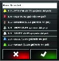
Press the job icon at the right side of the screen (Figure 11).
-
Press the name for the job (Figure 11).
Note: For the 1750 sprayers only, run the valve-balance wizard before selecting a nozzle.
-
Press the correct nozzle (Figure 12).
-
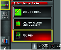
Expand the Auto Section Control (ASC) Configuration screen and press ASC ON (Figure 13).
-
Select the work region (Figure 10) that you are spraying (i.e. fairways, greens, tees, etc.).
-
Select the excluded region(s) that you are not spraying (bunkers, trees, hazards, etc.), as shown in Figure 10.
-
Press the master switch icon (Multi Pro 5800 only).
-
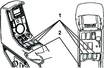
To start spraying, press the master switch to the ON position (Figure 16).
-
Press the section switches (located between the seats) to the ON position (Figure 16).
Note: The machine starts spraying when the sprayer crosses into the correct spray area.
Note: Spray at the appropriate speed based on the desired application rate and nozzles on the machine; refer to the Nozzle Selection Guide.
Spraying While Stationary
-
Press the job icon in the upper right of the screen (Figure 11).
-
Press the new job icon.
-
Type a new name for the job.
Note: For the 1750 sprayers only, run the valve-balance wizard before selecting a nozzle; refer to the GeoLink Operator’s Manual.
-
Select the correct nozzle.
-
Expand the Auto Section Control Configuration (ASC) mini view and press ASC OFF icon.
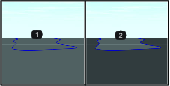
Note: The display shows spray active areas in light gray shading and non-spray areas in dark gray shading. If the display shows all light gray, you can spray the entire area.
-
Expand the sprayer controller mini view, press the manual speed icon, and enter your test speed.
-
Press the master switch icon (Multi Pro 5800 only), shown in Figure 2.
-
To start spraying, press the section switches (located between the seats) to the ON position (Figure 16).
Note: Spray at the appropriate speed based on the desired application rate and installed nozzles on the machine; refer to the Nozzle Selection Guide.