


Maintenance
Maintenance Safety Information
Warning
While maintenance or adjustments are being made, someone could start the engine. Accidental starting of the engine could seriously injure you or other bystanders.
Remove the key from the ignition switch, engage parking brake, and pull the wire(s) off the spark plug(s) before you do any maintenance. Also push the wire(s) aside so it does not accidentally contact the spark plug(s).
-
Park machine on level ground, raise the tines, set parking brake, stop engine, remove key or disconnect spark plug wire. Wait for all movement to stop and allow the machine to cool before adjusting, cleaning or repairing. Never allow untrained personnel to service machine.
Warning
The engine can become very hot. Touching a hot engine can cause severe burns.
Allow the engine to cool completely before service or making repairs around the engine area.
-
Disconnect battery or remove spark plug wire before making any repairs. Disconnect the negative terminal first and the positive last. Reconnect positive first and negative last.
-
Keep the machine, guards, shields and all safety devices in place and in safe working condition. Frequently check for worn or deteriorating components and replace them with the manufacturer’s recommended parts when necessary.
Warning
Removal or modification of original equipment, parts and/or accessories may alter the warranty, controllability, and safety of the machine. Unauthorized modifications to the original equipment or failure to use original Toro parts could lead to serious injury or death. Unauthorized changes to the machine, engine, fuel or venting system, may violate applicable safety standards such as: ANSI, OSHA and NFPA and/or government regulations such as EPA and CARB.
-
Use care when checking and servicing tines. Wrap the tine(s) or wear gloves, and use caution when servicing them. Only replace damaged tines. Never straighten or weld them.
-
Use jack stands to support the machine and/or components when required.
Caution
Raising the machine for service or maintenance relying solely on mechanical or hydraulic jacks could be dangerous. The mechanical or hydraulic jacks may not be enough support or may malfunction allowing the machine to fall, which could cause injury.
Do not rely solely on mechanical or hydraulic jacks for support. Use adequate jack stands or equivalent support.
-
Carefully release pressure from components with stored energy.
Warning
Hydraulic fluid escaping under pressure can penetrate skin and cause injury. Fluid accidentally injected into the skin must be surgically removed within a few hours by a doctor familiar with this form of injury or gangrene may result.
-
If equipped, make sure all hydraulic fluid hoses and lines are in good condition and all hydraulic connections and fittings are tight before applying pressure to hydraulic system.
-
Keep body and hands away from pinhole leaks or nozzles that eject high pressure hydraulic fluid.
-
Use cardboard or paper, not your hands, to find hydraulic leaks.
-
Before performing any work on the hydraulic system:
– Safely relieve all pressure in the ground drive hydraulic system by placing the motion control levers in neutral and shutting off the engine.
– Safely relieve all pressure in the auxiliary hydraulic system by shutting off the engine, turning the ignition switch to the “ON” position, and pressing the tine ground engagement switch. Once the tines have lowered to the ground, release the tine ground engagement switch and turn the ignition switch to the “OFF” position.
-
-
Keep hands and feet away from moving parts. If possible, Do Not make adjustments with the engine running. If the maintenance or adjustment procedure require the engine to be running and components moving, use extreme caution.
Warning
Contact with moving parts or hot surfaces may cause personal injury.
Keep your fingers, hands, and clothing clear of rotating components and hot surfaces.
-
Check all bolts frequently to maintain proper tightness.
Recommended Maintenance Schedule(s)
| Maintenance Service Interval | Maintenance Procedure |
|---|---|
| After the first 5 hours |
|
| After the first 100 hours |
|
| Before each use or daily |
|
| Every 25 hours |
|
| Every 50 hours |
|
| Every 80 hours |
|
| Every 100 hours |
|
| Every 160 hours |
|
| Every 250 hours |
|
| Every 500 hours |
|
| Every 800 hours |
|
| Monthly |
|
| Yearly |
|
Pre-Maintenance Procedures
Preparing for the Machine for Maintenance
Perform the following before servicing, cleaning, or making any adjustments to the machine.
-
Park the machine on a level surface.
-
Shut off the engine, engage the parking brake, wait for all moving parts to stop.
-
Remove the key from the key switch.
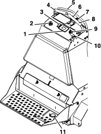
Accessing the Console Compartment
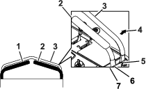
Removing the Console Pad
Installing the Console Pad
-
Align the 4 flanged-head bolts at the forward face of the console pad to the 4 keyhole slots in the frame of the console (Figure 30).
-
Move the pad forward until the pad is flush to the console frame (Figure 30).
-
Move the pad down until the flanged-head bolts are seated in the keyhole slots (Figure 30).
-
Tighten the flanged-head bolts to 1978 to 2542 N∙cm (175 to 225 in-lb).
Lubrication
Lubricating the Grease Fittings
| Maintenance Service Interval | Maintenance Procedure |
|---|---|
| Every 25 hours |
|
| Every 50 hours |
|
| Yearly |
|
Grease type: National Lubricating Grease Institute (NGLI) grade #2 multi-purpose gun grease.
Note: Refer to the lubrication chart for service intervals.
| Fitting Locations | Initial Pumps | Number of Places | Service Interval |
|---|---|---|---|
| Front caster pivots | *0 | 2 | Yearly |
| Jackshaft bearings | 1 | 8 | 25 hours |
| Wheel bearings | 1 | 2 | 25 hours |
| Tine shaft bearings | 1 | 4 | 25 hours |
| Tine assembly idlers | 1 | 2 | 25 hours |
| Control pivots | 1 | 4 | 50 hours |
| Belt idler pivot | 1 | 1 | Yearly |
| Front caster hubs | *0 | 2 | Yearly |
-
Shut off the engine, engage the parking brake, wait for all moving parts to stop, and remove the key.
-
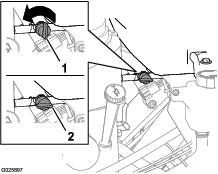
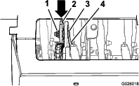
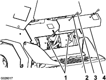
Wipe clean the grease fittings with a rag (Figure 31).
-
Connect a grease gun to the fitting (Figure 31).
-
Pump grease into the fittings until grease begins to ooze out of the bearings.
-
Wipe up any excess grease.
Lubricating the Chains
| Maintenance Service Interval | Maintenance Procedure |
|---|---|
| Before each use or daily |
|
Lubricant type: Oil or chain lubricant.
Important: Do not lubricate chains with penetrating oil or solvents.
-
Shut off the engine, engage the parking brake, wait for all moving parts to stop, and remove the key.
-
Raise the machine and support it with jack stands with a 460 kg (1,015 lb) capacity.
Caution
Raising the machine for service or maintenance relying solely on mechanical or hydraulic jacks could be dangerous. The mechanical or hydraulic jacks may not be enough support or may malfunction allowing the machine to fall, which could cause injury.
Do not rely solely on mechanical or hydraulic jacks for support. Use adequate jack stands or equivalent support.
-
Start the engine and move the throttle level ahead to the half-throttle position.
Warning
You must run the engine and turn the drive wheels so that you can perform adjustments. Contact with moving parts or hot surfaces may cause personal injury.
Keep your fingers, hands, and clothing clear of rotating components and hot surfaces.
-
Disengage the parking brake.
-
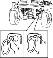
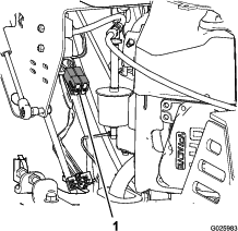
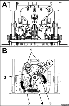
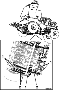
With the engine running, slowly move the motion-control levers forward and lubricate all 6 chains (Figure 69).
-
Check the condition and tension of the chains; refer to Checking the Condition and Tension of the Chains.
Lubricating the Casters
Grease type: National Lubricating Grease Institute (NGLI) grade No. 2 multi-purpose gun grease.
Greasing the Caster Pivots
| Maintenance Service Interval | Maintenance Procedure |
|---|---|
| Yearly |
|
-
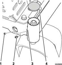
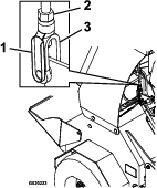
Remove cap and hex plug from the top of the caster pivot (Figure 32).
-
Thread grease fitting in hole (Figure 32).
-
Pump grease into the fitting until grease oozes out around top bearing (Figure 32).
-
Remove grease fitting and install the plug that you removed in 1 (Figure 32).
-
Install the cap that you removed in step 1 (Figure 32).
-
Repeat steps 1 through 5 to the other caster.
Lubricating the Caster-Hubs Bearings
| Maintenance Service Interval | Maintenance Procedure |
|---|---|
| Yearly |
|
Removing the Caster-Wheel Assembly
-
Shut off the engine, engage the parking brake, wait for all moving parts to stop, and remove the key.
-
Lift the front of the machine and support it with jack stands.
-
Remove the wheel nut and bolt, and remove the caster-wheel assembly from the fork (Figure 33).
Disassembling the Caster-Wheel Hub and Greasing the Bearings
| Maintenance Service Interval | Maintenance Procedure |
|---|---|
| Yearly |
|
Important: Use new bearing seals when lubricating the caster-wheel hubs.
Important: To prevent seal and bearing damage, check the bearing adjustment often. Spin the caster tire. The tire should not spin freely (more than 1 or 2 revolutions) or have any side play. If the wheel spins freely, adjust torque on spacer nut until there is a slight amount of drag. Apply thread-locking compound.
Grease type: National Lubricating Grease Institute (NGLI) grade No. 2 multi-purpose gun grease.
-
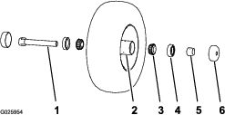
Remove the 2 seal guards from the wheel hub (Figure 34).
-
Remove 1 of the spacer nuts from the axle assembly in the caster wheel (Figure 34).
Note: Note that thread-locking compound has been applied to lock the spacer nuts to the axle (Figure 34).
-
Remove the axle (with the other spacer nut still assembled to it) from the caster-wheel assembly (Figure 34).
-
Pry out both bearing seals (Figure 34).
Note: Discard the old seals.
-
Remove both bearings and inspect them for wear or damage (Figure 34).
Note: Replace the bearing if it is worn or damaged.
-
Pack the 2 bearings with the specified grease.
Assembling the Caster-Wheel Hub
-
Install 1 bearing into the hub of the wheel (Figure 34).
-
Install the bearing seal into the hub at the bearing (Figure 34).
-
If you removed (or broke loose) both of the spacer nuts from the axle assembly, perform the following:
-
Clean the threads of the axle and spacer nut.
-
Apply a thread-locking compound to the threads at 1 end of the axle.
-
Thread the axle nut, with the wrench flats facing outward, onto the end of the axle that is prepared with thread-locking compound (Figure 34).
Note: Do not thread spacer nut all the way onto the axle. Leave approximately 3 mm (1/8 inch) from the outer surface of the spacer nut to the end of the axle inside the nut.
-
-
Insert the assembled nut and axle into the wheel at the side of the wheel with the new seal and bearing (Figure 34).
-
With the open end of the wheel facing up, fill the area inside wheel cavity (around the axle) with the specified grease.
-
Install the other bearing and new seal into the wheel (Figure 34).
-
Apply a thread-locking compound to the second spacer nut and thread it onto the axle with the wrench flats facing outward.
-
Torque the spacer nut to 8 to 9 N∙m (75 to 80 in-lb), loosen, then torque it 2 to 3 N∙m (20 to 25 in-lb).
Important: Ensure that the axle does not extend beyond either nut.
-
Install the seal guards over the wheel hub (Figure 34).
Installing the Caster-Wheel Assembly
-
Align the hole in the axle of the caster-wheel assembly between the holes in the fork of the caster (Figure 33).
-
Secure the wheel assembly to the fork with the wheel nut and bolt (Figure 33) that you removed in step 3 of Removing the Caster-Wheel Assembly.
-
Torque the wheel nut to 91 to 113 N∙m (67 to 83 ft-lb).
Engine Maintenance
Servicing the Air Cleaner
Inspect the foam and paper elements, and replace them if they are damaged or excessively dirty.
Important: Do not apply oil to the foam or paper element.
Accessing the Foam and Paper Elements
-
Shut off the engine, engage the parking brake, remove the key, and wait for all moving parts to stop before leaving the operating position.
-
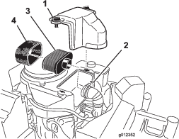
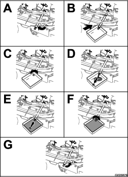
Clean around the air cleaner to prevent dirt from getting into the engine and causing damage (Figure 35).
-
Rotate the cover knobs 1/4 turn counterclockwise and remove the air-cleaner cover (Figure 35).
-
Rotate the thumbscrew of the hose clamp counterclockwise until you can separate the air-cleaner assembly from the inlet duct (Figure 35).
Servicing the Foam Air-Cleaner Element
| Maintenance Service Interval | Maintenance Procedure |
|---|---|
| Every 250 hours |
|
-
Carefully remove the foam element from the paper element (Figure 35).
-
Inspect the both elements for tears, an oily film, or damaged (Figure 35).
Important: Replace the element(s) if it is worn or damaged.
-
Wash the foam element in liquid soap and warm water. When the element is clean, rinse it thoroughly.
-
Dry the element by squeezing it in a clean cloth.
-
Assemble the foam element onto the paper element (Figure 35).
-
Install the air-cleaner elements onto the inlet duct of the engine (Figure 35).
-
Rotate the thumbscrew of the hose clamp clockwise (Figure 35).
-
Assemble the air-cleaner cover onto the engine and rotate the cover knobs 1/4 turn clockwise.
Replacing the Paper Air-Cleaner Element
| Maintenance Service Interval | Maintenance Procedure |
|---|---|
| Every 500 hours |
|
Important: Do not wash the paper air-cleaner element.
-
Discard the old paper element.
-
Assemble the foam element onto the new paper element (Figure 35).
-
Install the air-cleaner elements onto the inlet duct of the engine (Figure 35).
-
Rotate the thumbscrew of the hose clamp clockwise (Figure 35).
-
Assemble the air-cleaner cover onto the engine and rotate the cover knobs 1/4 turn clockwise.
Servicing the Engine Oil
Engine-Oil Specifications
Oil Type: Detergent oil (API service SJ or later)
Engine-Oil Capacity: 1.7 L (1.8 US qt) with the filter removed; 1.5 L (1.6 US qt) without the filter removed
Engine-Oil Viscosity: Refer to the table below.
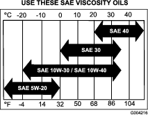
Checking the Engine-Oil Level
| Maintenance Service Interval | Maintenance Procedure |
|---|---|
| Before each use or daily |
|
Important: Do not operate the engine with the oil level below the Low (or Add) mark on the dipstick, or over the Full mark.
-
Park the machine on a level surface, engage the parking brake, shut off the engine, remove the key, and wait for all moving parts to stop before leaving the operating position.
-
Allow the engine to cool.
-
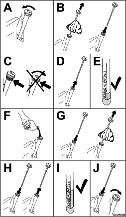
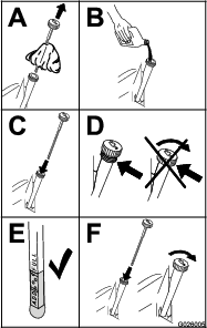
Check the engine-oil level as shown in Figure 37.

-
If the oil level is low, wipe off the area around the oil fill cap, remove cap and add the specified oil until the oil level is at the Full mark on the dipstick.
Note: Do not overfill the engine with oil.
Changing the Engine Oil
| Maintenance Service Interval | Maintenance Procedure |
|---|---|
| After the first 5 hours |
|
| Every 100 hours |
|
Note: Dispose of the used oil at a recycling center.
-
Park the machine so that the drain side is slightly lower than the opposite side to assure the oil drains completely.
-
Shut off the engine, engage the parking brake, remove the key, and wait for all moving parts to stop before leaving the operating position.
-
Change the engine oil as shown in Figure 39.
Note: Torque drain plug to 27 to 33 N∙m (20 to 24 ft-lb).

-
Slowly pour approximately 80% of the specified oil into the filler tube, and slowly add the additional oil to bring it to the Full mark (Figure 40).
-
Start the engine and drive to a flat area.
-
Check the engine-oil level.
-
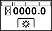
Reset the engine-oil service reminder; refer to Resetting the Engine-Oil Maintenance Reminder.
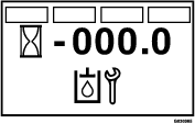
Resetting the Engine-Oil Maintenance Reminder
-
Prepare the machine for maintenance; refer to Preparing for the Machine for Maintenance.
Note: You must engage the parking brake to reset the maintenance reminder.
-
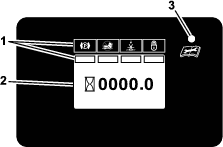
Cycle the key switch between the RUN position and the OFF position 4 times within 8 seconds.
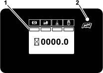
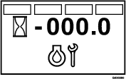
The Service Engine screen displays and flashes (Figure 41).
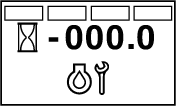
-
Press down the multi-function switch.
The engine-oil maintenance reminder resets to 100.0 (hours), exits the Service Engine screen, and returns to the default screen.
Note: You can exit the Service Engine screen at any time by turning the key to either the OFF or the START positions.
Changing the Engine-Oil Filter
| Maintenance Service Interval | Maintenance Procedure |
|---|---|
| After the first 5 hours |
|
| Every 100 hours |
|
-
Drain the oil from the engine; refer to Changing the Engine Oil.
-
Place a rag under the oil filter to soak up any spilled oil.
Important: Spilled oil may drain under the engine. Wipe up any spilled oil.
-
Change the engine-oil filter (Figure 42).

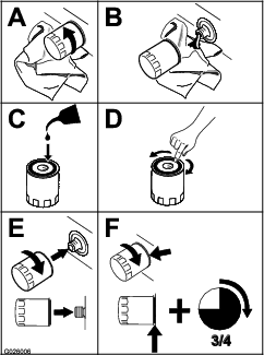
Note: Ensure that the oil-filter gasket touches the engine, and then turn the filter an extra 3/4 turn.
-
Fill the crankcase with the specified type of new oil; refer to Figure 36.
Servicing the Spark Plug
| Maintenance Service Interval | Maintenance Procedure |
|---|---|
| Every 160 hours |
|
Type for all Engines: NGK BPR4ES or equivalent
Air Gap: 0.75 mm (0.03 inch)
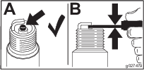
Make sure that the air gap between the center and side electrodes is correct before installing the spark plug.
Use a spark plug wrench for removing and installing the spark plug(s) and a gapping tool/feeler gauge to check and adjust the air gap. Install a new spark plug(s) if necessary.
Removing the Spark Plug
-
Shut off the engine, engage the parking brake, remove the key, and wait for all moving parts to stop before leaving the operating position.
-
Remove the spark plug as shown in Figure 43.

Checking the Spark Plug
Important: Do not clean the spark plug(s). Always replace the spark plug(s) when it has a black coating, worn electrodes, an oily film, or cracks.
If you see light brown or gray on the insulator, the engine is operating properly. A black coating on the insulator usually means the spark plug is dirty.
Set the gap to 0.75 mm (0.03 inch).
Installing the Spark Plug
Tighten the spark plug(s) to 22 N∙m (16 ft-lb).
Checking the Spark Arrester
| Maintenance Service Interval | Maintenance Procedure |
|---|---|
| Every 50 hours |
|
Warning
Hot exhaust system components may ignite fuel vapors even after the engine is shut off. Hot particles exhausted during engine operation may ignite flammable materials. Fire may result in personal injury or property damage.
Do not refuel or run engine unless spark arrester is installed.
-
Shut off the engine, engage the parking brake, remove the key, and wait for all moving parts to stop before leaving the operating position.
-
Allow the muffler to cool.
-
Check the spark arrester for breaks in the screen or welds.
Note: Replace the spark arrester if it is worn or damaged.
-
If you see that the screen is plugged, perform the following:
-
Remove the spark arrester.
-
Shake loose the particles from the arrester and clean screen with a wire brush.
Note: Soak the arrester screen in solvent if necessary.
-
Install spark arrester onto exhaust outlet.
-
Fuel System Maintenance
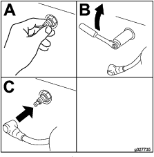
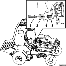
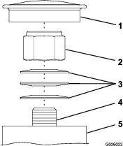
Servicing the Fuel Filter
Replacing the Fuel Filter
| Maintenance Service Interval | Maintenance Procedure |
|---|---|
| Every 800 hours |
|
Note: Wipe up any spilled fuel.
-
Shut off the engine, engage the parking brake, remove the key, and wait for all moving parts to stop before leaving the operating position.
-
Close the fuel-shutoff valve; refer to Using the Fuel-Shutoff Valve.
-
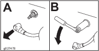
Squeeze the ends of the hose clamps together and slide them away from the filter (Figure 46).
-
Remove the filter from the fuel hoses (Figure 46).
Note: Do not install a dirty filter after it is removed from the fuel line.
-
Install a new filter with the flow-direction arrow aligned as illustrated in Figure 46.
Note: Ensure that the fuel hoses are fully seated onto the hose fittings of the fuel filter.
-
Align the hose clamps over the hose and the fuel-filter fittings (Figure 46).
-
Open the fuel-shutoff valve; refer to Using the Fuel-Shutoff Valve.
-
Check for fuel leaks and repair if needed.
-
Wipe up any spilled fuel.
Electrical System Maintenance
Checking the Safety-Interlock System
| Maintenance Service Interval | Maintenance Procedure |
|---|---|
| Before each use or daily |
|
Caution
If the safety-interlock switches are disconnected or damaged, the machine could operate unexpectedly, causing personal injury.
-
Do not tamper with the interlock switches.
-
Check the operation of the interlock switches daily and replace any damaged switches before operating the machine.
Understanding the Safety-Interlock System
The safety-interlock system is designed to prevent the engine from starting unless the motion-control levers are in the neutral position.
Checking the Safety-Interlock System
-
Disconnect the spark-plug wires.
-
While on level ground, block the wheels of the machine to prevent unintended movement.
-
Disengage the parking brake.
-
With the motion-control levers in the neutral position turn the key to the START position—the starter must not crank.
Note: If the machine does not pass this test, do not operate the machine. Contact your Authorized Service Dealer.
Important: It is essential that the operator safety mechanisms are connected and in proper operating condition prior to use.
Servicing the Battery
| Maintenance Service Interval | Maintenance Procedure |
|---|---|
| Monthly |
|
Always keep the battery clean and fully charged. Use a paper towel to clean the battery case. If the battery terminals are corroded, clean them with a solution of 4 parts water and 1 part baking soda. Apply a light coating of grease to the battery terminals to prevent corrosion.
Voltage: 12 V
Danger
Charging or jump starting the battery may produce explosive gases. Battery gases can explode causing serious injury.
-
Keep sparks, flames, or cigarettes away from battery.
-
Ventilate when charging or using battery in an enclosed space.
-
Make sure venting path of battery is always open once battery is filled with acid.
-
Always shield eyes and face from battery.
Danger
Battery electrolyte contains sulfuric acid, which is fatal if consumed and causes severe burns.
Do not drink electrolyte, and avoid contact with skin, eyes, and clothing. Wear safety glasses to shield your eyes and rubber gloves to protect your hands.
Caution
If the key switch is in the ON position, there is potential for sparks and engagement of components. Sparks could cause an explosion or moving parts could accidentally engage, causing personal injury.
Ensure that the key switch is in the OFF position before charging the battery.
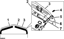
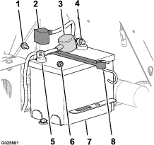
Removing the Battery
Warning
Battery terminals or metal tools could short against metal machine components, causing sparks. Sparks can cause the battery gasses to explode, resulting in personal injury.
-
When removing or installing the battery, do not allow the battery terminals to touch any metal parts of the machine.
-
Do not allow metal tools to short between the battery terminals and metal parts of the machine.
Warning
Incorrect battery-cable routing could damage the machine and cables, causing sparks. Sparks can cause the battery gasses to explode, resulting in personal injury.
-
Always disconnect the negative (black) battery cable before disconnecting the positive (red) cable.
-
Always connect the positive (red) battery cable before connecting the negative (black) cable.
-
Shut off the engine, engage the parking brake, remove the key, and wait for all moving parts to stop before leaving the operating position.
-
Remove the console pad; refer to Removing the Console Pad.
-
On the battery, lift the black terminal cover from the negative cable (Figure 47).
-
Disconnect the negative battery cable from the negative (-) battery terminal, and remove the cable from the battery (Figure 47).
-
Slide the red terminal cover off the positive battery terminal (Figure 47).
-
Disconnect the positive (red) battery cable, and remove the cable from the battery (Figure 47).
-
Remove the hook of the battery strap from the battery tray (Figure 47), and remove the battery.
Installing the Battery
-
Place the battery onto the machine (Figure 47).
-
Secure the battery to the battery tray with the battery strap.
-
Install the positive (red) battery cable to positive (+) battery terminal with a flanged bolt and flanged nut (Figure 47).
-
Slide the red terminal cover over the positive-battery terminal.
-
Install the negative battery cable and the ground wire to the negative (-) battery terminal with a flanged bolt and flanged nut (Figure 47).
-
Slide the black terminal cover over the negative-battery terminal.
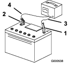
Charging the Battery
Warning
Charging the battery produces gasses that can explode.
Never smoke near the battery and keep sparks and flames away from the battery.
Important: Always keep the battery fully charged (1.265 specific gravity) to prevent battery damage when the temperature is below 0°C (32°F).
-
Remove the battery from the chassis; refer to Removing the Battery.
-
Check the electrolyte level.
-
Ensure that the filler caps are installed on the battery.
-
Charge the battery for 1 hour at 25 to 30 A or 6 hours at 4 to 6 A.
-
When the battery is fully charged, unplug the charger from the electrical outlet, and disconnect the charger leads from the battery posts (Figure 48).
-
Install the battery onto the machine and connect the battery cables; refer to Installing the Battery.
Note: Do not run the machine with the battery disconnected; electrical damage may occur.
Jump Starting a Discharged Battery
The following instructions are adapted from the SAE J1494 Rev. Dec. 2001 – Battery Booster Cables – Surface Vehicle Recommended Practice (SAE – Society of Automotive Engineers).
Danger
Jump starting a weak battery that is cracked, frozen, has low electrolyte level, or an open/shorted battery cell, can cause an explosion resulting in serious personal injury.
Do not jump start a weak battery if these conditions exist.
Warning
Batteries contain acid and produce explosive gases.
-
Always shield your eyes and face from the battery.
-
Do not lean over the batteries.
Preparing to Jump Start the Battery
Caution
Corrosion or loose connections can cause unwanted electrical voltage spikes at any time during the jump starting procedure.
Do Not attempt to jump start with loose or corroded battery terminals or damage to the engine may occur.
-
Check the cable clamps and battery terminals of the discharged battery for corrosion (white, green, or blue “snow”) and check that the hardware for the clamps is tight.
Clean corrosion from the battery terminals and cable clamps.
-
Check that the hardware for the cable clamps is tight.
Tighten the cable-clamp hardware as needed.
-
Check that the vent caps on the discharged battery and booster battery are tight and level.
-
If available, place damp clothes over the vent caps of both batteries.
-
If you are jump starting from the battery in another vehicle, ensure that it has a 12 V lead acid battery.
Important: Ensure that the 2 vehicles do not touch.
-
Ensure that the booster battery is fully charged with 12.6 volts or greater.
-
Select properly sized jumper cables (4 to 6 AWG) with short lengths to reduce voltage drop between systems.
Choose jumper cables with color coded or polarity labeled cables or clamps.
Connecting the Jumper Cables
Caution
Connecting the jumper cables incorrectly (wrong polarity) can immediately damage the electrical system.
Be certain of battery terminal polarity and jumper cable polarity when hooking up batteries.
-
Connect the positive jumper cable—red (+) to the positive-battery terminal of the discharged battery as shown in Figure 49.
Note: The positive-battery terminal is wired to the starter or solenoid
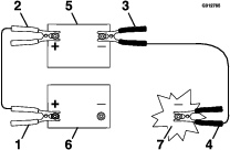
-
Connect the other end of the positive cable to the positive-battery terminal of the booster battery (Figure 49).
-
Connect the negative jumper cable—black (–) to the negative-battery terminal of the booster battery.
-
At the machine with a discharged battery, connect the other end of the negative jumper cable to the engine block, at a location away from the battery and belts (Figure 49).
Starting the Engine and Removing the Jumper Cables
Servicing the Fuses
The electrical system is protected by fuses, and requires no maintenance. If a fuse blows, check the component or circuit for a malfunction or short.
-
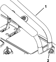
Release the cushion from the rear of the machine.
-
Remove the negative-battery cable from the battery terminal.
Note: Ensure that the negative battery cable does not touch the battery terminal.
-
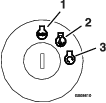
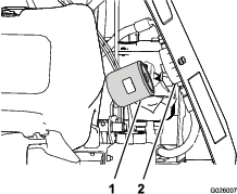
Pull the fuse from the socket of the fuse block (Figure 50).
-
Install a fuse of the same type and amperes into the socket of the fuse block (Figure 50).
-
Install the negative-battery cable from the battery terminal; refer to steps 5 and 6 of Installing the Battery.
Drive System Maintenance
Checking the Air Pressure in the Tires
| Maintenance Service Interval | Maintenance Procedure |
|---|---|
| Every 50 hours |
|
Note: The semi-pneumatic caster tires do not need to be inflated.
-
Shut off the engine, engage the parking brake, remove the key, and wait for all moving parts to stop before leaving the operating position.
-
Check the pressure of the drive tires.
-
Inflate the drive tires to 83 to 97 kPa (12 to 14 psi).
Checking the Wheel Hub Nuts
| Maintenance Service Interval | Maintenance Procedure |
|---|---|
| After the first 5 hours |
|
| Yearly |
|
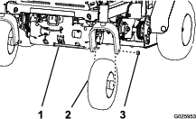
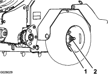
Torque the wheel hub nuts (Figure 51) to 285 to 350 N∙m (210 to 260 ft-lb).
Note: Do not use anti-seize compound on the wheel hub.
Checking the Torque of the Wheel Lug Nuts
| Maintenance Service Interval | Maintenance Procedure |
|---|---|
| Yearly |
|
Torque the wheel lug nuts (Figure 51) to 122 to 129 N∙m (90 to 95 ft-lb).
Checking the Torque of the Transmission Output Shaft Nut
| Maintenance Service Interval | Maintenance Procedure |
|---|---|
| After the first 5 hours |
|
| Yearly |
|
Torque the nut (Figure 52) on the transmission output tapered shaft to 285 to 353 N∙m (210 to 260 ft-lb).
Adjusting the Caster Pivot Bearings Pre-Load
Note: If you disassemble the caster pivot bearings, ensure that the spring-disc washers are installed as shown in Figure 53.
Brake Maintenance
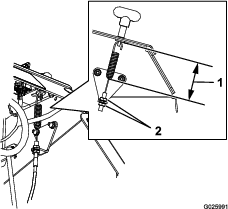
Adjusting the Parking Brake
If the parking brake does not hold securely, an adjustment is required.
-
Park the machine on a level surface.
-
Shut off engine and wait for all moving parts to stop.
-
Check the air pressure in the drive tires.
Note: If needed, adjust to the recommended inflation; refer to Checking the Air Pressure in the Tires.
-
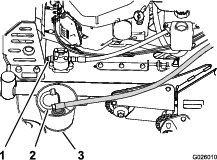
Loosen the jam nut on the brake cable under the console (Figure 54).
-
Engage the parking brake (Figure 54).
-
Adjust the jam nut position until 7.9 cm (3-1/8 inch) from the bottom of the link to the bottom of the spring (Figure 54).
-
Secure the adjustment of the cable by tightening the jam nuts (Figure 54).
-
Check the parking brake; if necessary, repeat steps 4 through 7.
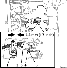
Adjusting the Brake Switch
-
Park the machine on a level surface.
-
Shut off the engine and wait for all moving parts to stop.
-
Prior the adjusting the brake switch ensure that the parking brake is properly adjusted; refer to Adjusting the Parking Brake.
-
Engage the parking brake.
-
Check the distance between the parking brake-switch bracket to the brake arm of the transmission (Figure 55).
Note: The distance should be 3.2 mm (1/8 inch).
-
If adjustment is required, preform the following:
-
Loosen the locknut and carriage bolt securing the parking brake switch bracket (Figure 55).
-
Adjust the position of the brake-switch bracket until the gap (Figure 55) between the switch bracket and the brake arm is 3.2 mm (1/8 inch)
-
Tighten the locknut and carriage bolt (Figure 55) securing the brake-switch bracket to 1017 to 1243 N∙cm (90 to 110 in-lb).
-
Belt Maintenance
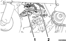
Checking the Condition and Tension of the Belts
| Maintenance Service Interval | Maintenance Procedure |
|---|---|
| Every 50 hours |
|
-
Shut off the engine, engage the parking brake, remove the key, and wait for all moving parts to stop before leaving the operating position.
-
Raise the machine and support it with jack stands with a 460 kg (1,015 lb) capacity.
-
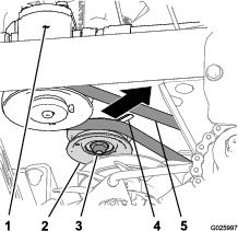
Check the auxiliary pump-drive belt condition and tension (Figure 56).
Note: The belt should deflect 1.3 cm (1/2 inch) when 1.4 kg (3 lb) of force is applied to the belt midway between the auxiliary pump and engine pulleys. If the belt tension is too high or too low, refer to Adjusting the Auxiliary Pump-Drive Belt.
-
Check condition of the transmission-drive belt (Figure 56).
Note: The transmission belt has an automatic-spring tensioner.
Adjusting the Auxiliary Pump-Drive Belt
-
Shut off the engine, engage the parking brake, remove the key, and wait for all moving parts to stop before leaving the operating position.
-
Loosen the locknut (3/8 inch) that secures the auxiliary pump-idler pulley to the chassis of the machine.
-
Adjust the belt tension as follows:
-
Move the auxiliary pump-idler pulley rearward and outward to tighten the belt.
-
Move the auxiliary pump-idler pulley forward and inward to loosen the belt.
Note: The belt should deflect 1.3 cm (1/2 inch) when 1.4 kg (3 lb) of force is applied to the belt midway between the auxiliary pump and engine pulleys.
-
-
Tighten locknut to 37 to 45 N∙m (27 to 33 ft-lb).
Replacing the Transmission-Drive Belt
Note: No adjustments are required for belt tension.
-
Shut off the engine, engage the parking brake, remove the key, and wait for all moving parts to stop before leaving the operating position.
-
Insert a breaker bar into the socket of the belt-tension bracket and move the bracket outward and forward (Figure 58).
-
Slip the transmission-drive belt of the engine, tensioner, and transmission pulleys (Figure 58).
-
Route the new transmission-drive belt around the engine, tensioner, and transmission pulleys as shown in Figure 58
-
Release the belt-tension bracket and allow the spring to tension the belt (Figure 58).
Note: Make sure that the belt-tension bracket and pulley can move freely.
Controls System Maintenance
Adjusting the Traction-Control Linkage
-
Park the machine on a level surface.
-
Shut off the engine, engage the parking brake, remove the key, and wait for all moving parts to stop before leaving the operating position.
-
Push the control lever all the way forward toward the front reference bar.
-
If the control lever contacts the reference bar or If the gap between the control lever and reference bar is larger than 1.6 mm (1/16 inch), perform the following:
-
Release the control lever and allow it to return to the neutral position.
-
Remove the spring-clevis pin from the fork fitting of the traction-control linkage (Figure 59).
-
Adjust the fork fitting to set the initial gap as follows:
-
Install the spring clevis pin (Figure 59) and move the control lever forward.
-
Repeat steps 1 through 4 until there is a gap approximately 1.6 mm (1/16 inch) between the control lever and the front reference bar.
-
Remove the spring-clevis pin, rotate the turnbuckle clockwise 1 additional turn, and insert the spring-clevis pin (Figure 59).
-
-
Repeat steps 41 through 46 for the other traction-control linkage.
Hydraulic System Maintenance
Maintaining the Auxiliary Hydraulic System
Hydraulic Fluid Specification
AW-32 hydraulic fluid
Checking the Auxiliary Hydraulic-Fluid Level
| Maintenance Service Interval | Maintenance Procedure |
|---|---|
| Every 50 hours |
|
-
Park the machine on a level surface.
-
Lower the tines to the ground.
-
Shut off the engine, engage the parking brake, remove the key, and wait for all moving parts to stop before leaving the operating position.
-
Remove the console pad; refer to Removing the Console Pad.
-
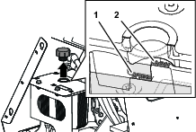
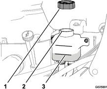
Clean the area around the hydraulic reservoir cap (Figure 60).
-
Remove the cap and check hydraulic-fluid level in the reservoir (Figure 60).
Note: The hydraulic-fluid level should cover the word Cold that is embossed into the baffle of the reservoir.
-
If necessary, add the specified hydraulic fluid to the reservoir until the fluid covers the Cold fluid level on the baffle (Figure 60).
Note: The baffle ion the reservoir is labeled Hot and Cold. Fill the reservoir to the appropriate level depending upon the temperature of the fluid. The fluid level varies with the temperature of the fluid. The Cold level shows the level of the fluid when it is at 24°C (75°F). The Hot level shows the level of fluid when it is at 107°C (225°F). For example: If the fluid is at ambient-air temperature, about 24°C (75° F), fill only to the Cold level. If the fluid is about 65°C (150° F), fill to halfway between the Hot and Cold levels.
-
Replace the hydraulic reservoir cap and tighten it until it is snug (Figure 60).
Note: Do not overtighten the reservoir cap.
-
Install the console pad; refer to Removing the Console Pad.
Changing the Auxiliary Hydraulic Reservoir Fluid and Filter
| Maintenance Service Interval | Maintenance Procedure |
|---|---|
| After the first 100 hours |
|
| Every 250 hours |
|
-
Shut off the engine, engage the parking brake, remove the key, and wait for all moving parts to stop before leaving the operating position.
-
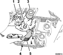
Carefully clean area around the front of the auxiliary pump, fill cap for the reservoir, and filter (Figure 61).
Important: Ensure that no dirt or contamination enters hydraulic system.
-
At the front of the auxiliary hydraulic pump, remove the inlet hose from the hydraulic fitting in the pump, place the end of the hose in a drain container, and allow the fluid to drain (Figure 62).
-
Clean around the fitting for the hydraulic pump.
-
Rotate the auxiliary hydraulic filter counterclockwise and remove it from the base of the filter adapter (Figure 63). Allow the fluid to drain.
-
Apply a thin coat of specified fluid onto the seal of the new hydraulic filter.
-
Install the filter by rotating it clockwise onto the filter adapter until the seal contacts the filter adapter, then tighten the filter an additional 2/3 to 3/4 turn (Figure 63).
-
Install the inlet hose onto the fitting in the pump and torque the hose fitting to 50 N∙m (37 ft-lb).
-
Add the specified fluid until the level reaches the Cold fill line located on the reservoir tank; refer to Checking the Auxiliary Hydraulic-Fluid Level.
-
Start the engine and raise and lower the tines.
-
Lower the tines to the ground and refill the reservoir to the Cold fill line.
Maintaining the Transmission
Transmission Fluid Specification
Toro® HYPR-OIL™ 500 hydraulic fluid or Mobil® 1 15W-50 synthetic motor oil.
Important: Use the specified fluid. Other fluids could cause system damage.
Checking the Transmission Fluid Level
| Maintenance Service Interval | Maintenance Procedure |
|---|---|
| Every 50 hours |
|
-
Shut off the engine, engage the parking brake, remove the key, and wait for all moving parts to stop before leaving the operating position.
-
Allow the machine to cool.
-
Remove the cap from the expansion tank and check the hydraulic-fluid level in the tank (Figure 64).
Note: The transmission fluid level should cover the Full Cold line molded into the side of the tank.
-
If necessary, add the specified transmission fluid until the fluid level is at the Full Cold line of the expansion tank (Figure 64).
-
Replace expansion-tank cap and tighten it until snug.
Important: Do not overtighten the expansion-tank cap.
Changing the Transmission Filters
| Maintenance Service Interval | Maintenance Procedure |
|---|---|
| After the first 100 hours |
|
| Every 250 hours |
|
Note: Do not change the hydraulic system fluid (except for what can be drained when changing filter), unless the fluid has been contaminated or been extremely hot.
-
Shut off the engine, engage the parking brake, remove the key, and wait for all moving parts to stop before leaving the operating position.
-
Raise the machine and support it with jack stands with a 460 kg (1,015 lb) capacity.
-
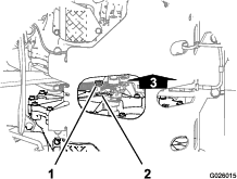
Remove the 3 washer-head bolts (1/4 x 3/4 inch) that secure the filter guard to the transmission, and remove the guard (Figure 65).
-
Clean the around the transmission filter (Figure 65).
-
Align a drain pan under the filter.
-
Rotate the filter counterclockwise and remove the filter (Figure 65).
Note: Allow the fluid to completely drain from the filter adapter of the transmission.
-
Apply a thin coat of specified fluid onto the seal of the new transmission filter.
-
Install the filter by rotating it clockwise onto the filter adapter until the seal contacts the base of the adapter, then tighten the filter an additional 3/4 to 1 turn (Figure 65).
-
Install the filter guard with the 3 washer-head bolts (1/4 x 3/4 inch) that you removed in step 3 (Figure 65), and tighten the bolts to 1117 to 1243 N∙cm (90 to 110 in-lb).
Filling the Transmissions with Fluid
| Maintenance Service Interval | Maintenance Procedure |
|---|---|
| After the first 100 hours |
|
| Every 250 hours |
|
-
Raise the rear of machine up and support with jack stands (or equivalent support) just high enough to allow the drive wheels to turn freely.
Caution
Raising the machine for service or maintenance relying solely on mechanical or hydraulic jacks could be dangerous. The mechanical or hydraulic jacks may not be enough support or may malfunction allowing the machine to fall, which could cause injury.
Do not rely solely on mechanical or hydraulic jacks for support. Use adequate jack stands or equivalent support.
-
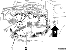
Align a drain pan under the sight plugs of the transmissions (Figure 66 and Figure 67).
-
At the inboard side of the transmission, near the top, remove the sight plug from 1 of the transmissions (Figure 66 and Figure 67).
-
Add the specified fluid to the expansion tank until fluid flows from the sight-plug port; refer to Checking the Transmission Fluid Level.
-
Install the sight plug and torque it to 244 N∙m (180 in-lb).
-
Repeat steps 3 through 5 for the other transmission.
-
Add the specified fluid into the expansion tank until the fluid level is at the Full Cold line of the tank.
-
Start the engine and move the throttle midway between the SLOW and FAST positions
-
Disengage the parking brake.
-
Slowly move the motion-control levers in the forward and reverse directions 5 to 6 times.
Note: Cycling the traction-controls forward and reverse purges air from the transmissions.
-
Shut off the engine and remove the key.
-
Check the fluid level in the expansion tank, and add the specified fluid as required; refer to Checking the Transmission Fluid Level.
-
Repeat steps 8 through 12 until all the air is completely purged from the transmissions.
Note: The air is purged when the transmissions when the transmissions operate at normal noise levels and smoothly move forward and reverse at normal speeds.
-
Lower the machine and remove the jack stands.
-
Reset the transmission-oil maintenance reminder; refer to Resetting the Transmission-Oil Maintenance Reminder.
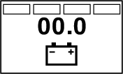
Resetting the Transmission-Oil Maintenance Reminder
-
Prepare the machine for maintenance; refer toPreparing for the Machine for Maintenance.
Note: You must engage the parking brake to reset the maintenance reminder.
-
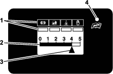
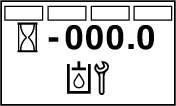
Cycle the key switch between the RUN position and the OFF position 6 times within 8 seconds.
The Service Transmission screen displays and flashes (Figure 68).
-
Press down the multi-function switch.
The transmission-oil maintenance reminder resets to 250 (hours), exits the service transmission screen, and returns to the default screen.
Note: You can exit the service transmission screen at any time by turning the key to either the OFF or the START positions.
Chain Maintenance
Checking the Condition of the Sprockets
| Maintenance Service Interval | Maintenance Procedure |
|---|---|
| Before each use or daily |
|
-
Shut off the engine, engage the parking brake, wait for all moving parts to stop, and remove the key.
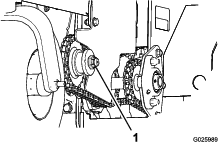
-
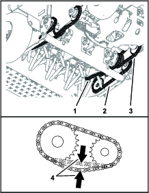
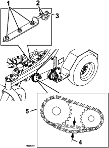
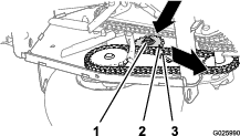
Inspect sprockets for wear and replace as required (Figure 69).
Checking the Condition and Tension of the Chains
| Maintenance Service Interval | Maintenance Procedure |
|---|---|
| Before each use or daily |
|
-
Shut off the engine, engage the parking brake, wait for all moving parts to stop, and remove the key.
-
Check the condition and chain tension for the following chains at both sides of the machine:
-
Jackshaft drive-chain
-
Drive wheel chain
-
Tine drive chain
The chains should move up and down 6 to 12 mm (1/4 to 1/2 inch).
-
-
If the chains pop, snap, or the tension is incorrect, adjust the chain tension; refer to Adjusting the Jackshaft Drive-Chain Tension, Adjusting the Drive Wheel Chain Tension, or Adjusting the Tine Drive Chain.
Adjusting the Jackshaft Drive-Chain Tension
-
Shut off the engine, engage the parking brake, remove the key, and wait for all moving parts to stop before leaving the operating position.
-
Lift the rear of the machine and support it using jack stands or equivalent support.
-
Check the chains on both sides of the machine for proper tension.
Note: The chains should move up and down 6 to 12 mm (1/4 to 1/2 inch).
-
At each side of the machine, loosen the 3 nuts and bolts that secure the transmission mount and tensioner plate, and the 2 nuts securing the adjustment bolt at the tensioner plate as shown in Figure 71.
Note: You must loosen the nuts and bolts that secure the transmission mount and tensioner plate at both sides of the machine.
-
Turn the adjustment bolt to move transmission adjustment plates and transmission.
-
When the chains can move up and down 6 to 12 mm (1/4 to 1/2 inch), tighten the nuts on both sides of the adjustment bolts.
-
Tighten nuts and bolts that secure the hydro mounting.
-
Adjust the traction-control linkage, refer to Adjusting the Traction-Control Linkage.
Adjusting the Drive Wheel Chain Tension
-
Shut off the engine, engage the parking brake, remove the key, and wait for all moving parts to stop before leaving the operating position.
-
Lift the rear of the machine and support it using jack stands.
-
Check the tension of the drive-wheel chains (Figure 72).
Note: The chains should move up and down 6 to 12 mm (1/4 to 1/2 inch).
-
Loosen the locknut and carriage bolt that secure the idler sprocket (Figure 72).
-
Increase or decrease chain tension by performing the following:
-
Push down and forward on the sprocket to increase the chain tension as shown in Figure 72.
-
Lift up and back on the sprocket to decrease the chain tension.
-
-
Torque the locknut to 91 to 113 N∙m (67 to 83 ft-lb).
-
Check the chain tension and if necessary repeat steps 4 through 6 until you can move the chain up and down 6 to 12 mm (1/4 to 1/2 inch).
Adjusting the Tine Drive Chain
-
Shut off the engine, engage the parking brake, remove the key, and wait for all moving parts to stop before leaving the operating position.
-
Remove the rear cover; refer to step 3 of Checking the Tines.
-
Check the chains on both sides of the machine for proper tension.
Note: The chains should move up and down 6 to 12 mm (1/4 to 1/2 inch).
-
Loosen the locknut and carriage bolt that secure the idler sprocket (Figure 73).
-
Increase or decrease chain tension by performing the following:
-
Push down and forward on the sprocket to increase the chain tension as shown in Figure 73.
-
Lift up and back on the sprocket to decrease the chain tension.
-
-
Torque the locknut to 91 to 113 N∙m (67 to 83 ft-lb).
-
Check the chain tension and if necessary repeat steps 4 through 6 until you can move the chain up and down 6 to 12 mm (1/4 to 1/2 inch).
-
Install the rear panel; refer to steps 6 and 7 of Checking the Tines.
Tine Maintenance
Checking the Tines
| Maintenance Service Interval | Maintenance Procedure |
|---|---|
| Before each use or daily |
|
-
Shut off the engine, engage the parking brake, remove the key, and wait for all moving parts to stop before leaving the operating position.
-
Raise the machine and support it with jack stands with a 460 kg (1,015 lb) capacity.
Caution
Raising the machine for service or maintenance relying solely on mechanical or hydraulic jacks could be dangerous. The mechanical or hydraulic jacks may not be enough support or may malfunction allowing the machine to fall, which could cause injury.
Do not rely solely on mechanical or hydraulic jacks for support. Use adequate jack stands or equivalent support.
-
Remove the 2 bolts (3/8 x 1 inch) and 2 washers (3/8 inch) that secure the rear-cover panel to the chassis, and remove the panel (Figure 74).
-
Remove rocks and other debris from the tines.
-
Inspect the tines for wear and damage.
Note: Replace any tines that are worn or damaged.
-
Align the holes in the rear-cover panel to the holes in the chassis (Figure 74).
-
Secure the cover panel to the chassis with the 2 bolts and 2 washers (Figure 74) that you removed in step 3, and torque the bolts to 37 to 45 N∙m (27 to 33 in-lb)
Chassis Maintenance
Checking for Loose Hardware
| Maintenance Service Interval | Maintenance Procedure |
|---|---|
| Before each use or daily |
|
-
Shut off the engine, engage the parking brake, remove the key, and wait for all moving parts to stop.
-
Visually inspect machine for any loose hardware or any other possible problem.
Note: Tighten all loose hardware or repair the problem before operating the machine.
Cleaning
Wash the machine as needed using water alone or with a mild detergent. You may use a rag when washing the machine.
Important: Do not use brackish or reclaimed water to clean the machine.
Important: Do not use power-washing equipment to wash the machine. Power-washing equipment may damage the electrical system, loosen important decals, or wash away necessary grease at friction points. Avoid excessive use of water near the control panel, engine, and battery.
Important: Do not wash the machine with the engine running. Washing the machine with the engine running may result in internal engine damage.
Cleaning the Engine and the Exhaust System Area
| Maintenance Service Interval | Maintenance Procedure |
|---|---|
| Before each use or daily |
|
Caution
Excessive debris around engine cooling air intake and exhaust system area can cause engine, exhaust area, and hydraulic system to overheat, which can create a fire hazard.
Clean all debris from engine and exhaust system area.
-
Shut off the engine, engage the parking brake, remove the key, and wait for all moving parts to stop before leaving the operating position.
-
Clean all debris from screen at the top of the engine, around engine shrouding, and exhaust system area.
-
Wipe up any excessive grease or oil around the engine and exhaust system area.
Removing the Engine Shrouds and Cleaning the Cooling Fins
| Maintenance Service Interval | Maintenance Procedure |
|---|---|
| Every 80 hours |
|
-
Shut off the engine, engage the parking brake, remove the key, and wait for all moving parts to stop before leaving the operating position.
-
Remove cooling shrouds from engine.
-
Clean cooling fins of the engine.
Note: Also clean dust, dirt, and oil from external engine surfaces, which can cause improper cooling.
-
Install the cooling shrouds into the engine.
Important: Operating the engine without the cooling shrouds will cause engine damage from overheating.
Cleaning the Debris from the Machine
| Maintenance Service Interval | Maintenance Procedure |
|---|---|
| Before each use or daily |
|
Important: Wash the machine with mild detergent and water. Do not pressure wash the machine. Avoid excessive use of water, especially near the control panel, around the engine, hydraulic pumps, and motors.
-
Shut off the engine, engage the parking brake, remove the key, and wait for all moving parts to stop before leaving the operating position.
-
Clean off any oil, debris, or grass buildup on the machine and aerator deck.
-
Clean off any debris or grass under the chain guards, around the fuel tank, and around the engine and exhaust area.
Waste Disposal
Disposing of the Engine Oil
Engine oil and hydraulic fluid are both pollutants to the environment. Dispose of used oil at a certified recycling center or according to your state and local regulations.
Disposing of the Battery
Danger
Battery electrolyte contains sulfuric acid, which is poisonous and can cause severe burns. Swallowing electrolyte can be fatal or can cause severe burns if it touches skin.
-
Wear safety glasses to shield eyes, and rubber gloves to protect skin and clothing when handling electrolyte.
-
Do not swallow electrolyte.
-
In the event of an accident, flush with water and call a doctor immediately.
Federal law states that batteries should not be placed in the garbage. Management and disposal practices for batteries must follow relevant federal, state, or local laws.
If you are replacing the battery or your machine is no longer operated and it is being scrapped—remove the battery; take the battery to a local certified recycling center. If no local recycling is available return the battery to any certified battery reseller.