Safety
Safety and Instructional Decals
 |
Safety decals and instructions are easily visible to the operator and are located near any area of potential danger. Replace any decal that is damaged or missing. |
Installation
Determine the left and right sides of the machine from the normal operating position.
Preparing the Machine
-
Park the machine on a level surface.
-
Disengage the power takeoff and lower the attachments.
-
Engage the parking brake.
-
Shut off the engine and remove the key.
-
Wait for all movement to stop.
-
Allow machine components to cool.
Installing the Kit
Parts needed for this procedure:
| Sensor module | 1 |
| Bolt | 2 |
| Nut | 2 |
| Mounting bracket | 1 |
| Wire harness | 1 |
| Alarm | 1 |
| Plastic plug | 4 |
| Cable tie | 2 |
Installing the Sensor Module
-
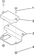
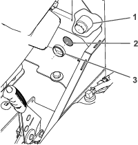
Secure the sensor module to the mounting bracket using 2 bolts and nuts (Figure 1).
-
Torque the fasteners to 4.2 N∙m (37 in-lb).
-
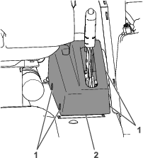
Remove and discard the plastic plugs securing the parking brake cover to the machine (Figure 2). Remove the parking brake cover.
Note: Use a putty knife or a plastic-fastener removal tool when removing the plastic plugs.
-
Raise the left side of the machine and remove the front left tire. Refer to Raising the Machine in the Operator’s Manual.
-
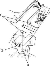
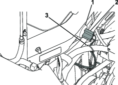
Remove the nuts shown in Figure 3.
Note: Do not remove the bolts from the machine.
-
Secure the mounting bracket to the machine using the bolts and nuts (Figure 3).
Installing the Alarm
-
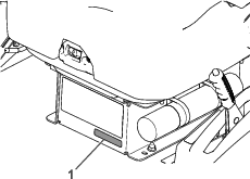
Remove the knockout from the panel behind the parking brake (Figure 4).
-
Remove the plastic nut from the alarm and use it to secure the alarm through the opening left by the knockout (Figure 4).
-
Install the previously removed parking brake cover using 4 new plastic plugs to secure it to the machine (Figure 2).
Note: You do not need to install the 2 outer plastic plugs on machines with cabs.
Routing the Wire Harness
-
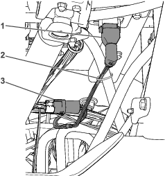
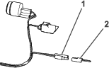
Plug the 90° connector into the bottom of the sensor module (Figure 5).
-
Route the wire harness back and plug the second connector into the machine wire harness (Figure 5).
-
Plug the very end of the wire harness into the previously installed alarm (Figure 6).
-
Secure the harness to the hydraulic tube with a cable tie as shown in Figure 5.
-
Secure the harness away from A/C compressor belt on cab units as shown in Figure 6.
Installing the Decal
Parts needed for this procedure:
| Decal | 1 |
-
Install the decal on the machine as shown in Figure 7.
-
Install the front left tire, torque the lug nuts, and lower the machine. Refer to Installing the Front Tires in the Operator’s Manual.
Calibrating the Sensor
-
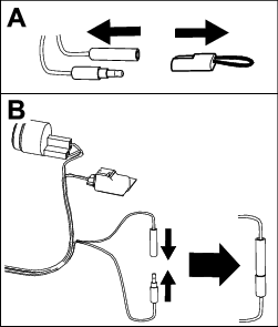
While on a flat surface, remove the plug from the calibration connectors (Figure 8).
-
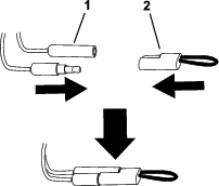
Plug the calibration connectors together as shown in Figure 8.
-
Turn the ignition key to the ON position, but do not start the engine.
-
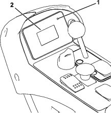
The displays shows Slope Sensor Calibrating.
Note: The LED light next to the display screen (Figure 9) is solid green as the sensor calibrates.
-
When the display shows Slope Sensor Calibrated, turn the ignition key to the OFF position.
-
Disconnect the calibration connectors and install the plug onto the connectors (Figure 10).
Operation
Using the Slope Sensor
The light and alarm indicates the severity of the slope:
-
Green light—normal operating conditions
-
Slow, flashing red light and B2713 displaying on the screen—moderate slope
-
Fast, flashing red light, audible alarm, and B2714 displaying on the screen—steep slope; proceed to a more shallow slope.
Warning
Slopes are a major factor related to loss-of-control and tip-over accidents, which can result in severe injury or death.
Use extreme caution when operating the machine on a slope.