Determine the left and right sides of the machine from the normal operating position.
Installation
Preparing the Machine
-
Park the machine on a level surface.
-
Engage the parking brake.
-
Shut off the engine and remove the key.
Installing the Front Carrier Frames
Parts needed for this procedure:
| Right link bracket | 2 |
| Left link bracket | 2 |
| Carriage bolt | 4 |
| Flat washer | 4 |
| Locknut | 4 |
| Bushing | 4 |
| Long pull-arm extension | 4 |
| Bolt—3/8 x 1-1/2 inches (2006 and earlier machines only) | 4 |
| Roller shaft (2007 and after machines only) | 4 |
| Bolt—3/8 x 2 inches (2007 and after machines only) | 4 |
| Bushing (2007 and after machines only) | 8 |
2006 and Earlier Machines
-
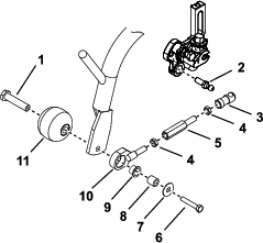
Slide back the sleeve on the ball-joint receiver and remove the receiver from the ball stud (Figure 1).
-
Remove the bolts and roller shafts securing the anti-scalp rollers and the pull-link assemblies to each carrier frame (Figure 1).
-
Disassemble the pull-link assemblies (Figure 1).
-
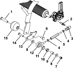
Thread the previously removed jam nut onto each of the new longer pull-arm extensions and onto the existing pull-link and bushing assemblies (Figure 2)
-
Assemble the new longer pull-arm extensions to the existing pull-link assemblies and ball-joint receiver assemblies (Figure 2). Do not tighten the jam nuts at this time.
-
Mount the appropriate link bracket (left or right) and a previously removed anti-scalp roller to the end of each front carrier frame with a new carriage bolt and the previously removed roller shaft. Position the brackets as shown in Figure 2.
-
Mount a pull-link assembly to the outside of each link bracket with a bolt (3/8 x 1-1/2 inches), flat washer, bushing, the previously removed spacer and flat washer, and a new locknut (Figure 2).
Note: Make sure that the bushing is inside the pull-link assembly.
-
Slide back the sleeve on the ball-joint receivers and install the receivers onto the ball studs (Figure 2).
-
Mount a basket onto the carrier frame.
-
Adjust the pull arms until there is a 6 to 10 mm (1/4 to 3/8 inch) clearance between the lip of the basket and the reel blades.
Note: Make sure the basket lips are parallel with the reel blades all the way across the reel blades.
-
Tighten the jam nuts.
2007 and Later Machines
-
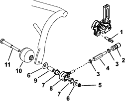
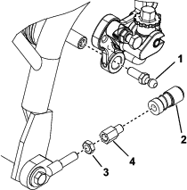
Slide back the sleeve on the ball-joint receiver and remove the receiver from the ball stud (Figure 3)
-
Remove the locknuts and roller shafts securing the anti-scalp rollers and the pull-link assemblies to each carrier frame (Figure 3).
-
Disassemble the pull-link assemblies (Figure 3).
-
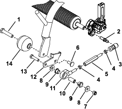
Thread a previously removed jam nut onto each of the new longer pull-arm extensions and onto the existing pull-link and bushing assemblies (Figure 4).
-
Assemble the new longer pull-arm extensions to the existing pull-link assemblies and ball-joint receiver assemblies (Figure 4). Do not tighten the jam nuts at this time.
-
Mount the appropriate link bracket (left or right) and a previously removed anti-scalp roller to the end of each front carrier frame with a new carriage bolt and roller shaft. Position the brackets as shown in Figure 4.
-
Mount a pull-link assembly to the outside of each link bracket with a new bolt (3/8 x 2 inches), previously removed flat washer, 2 new bushings, a previously removed spacer, flat washer and locknut. Position the components as shown in Figure 4.
Note: Make sure that the bushings are inside the pull-link assembly.
-
Slide back the sleeve on the ball-joint receivers and install the receivers onto the ball studs (Figure 4).
-
Mount a basket onto the carrier frame.
-
Adjust the pull arms until there is a 2 to 3 mm (1/16 to 1/8 inch) clearance between the lip of the basket and the reel blades.
Note: Make sure that the basket lips are parallel with the reel blades all the way across the reel blades.
-
Tighten the jam nuts.
Installing the Rear Carrier Frame
Parts needed for this procedure:
| Short pull-arm extension | 2 |
-
Slide back the sleeve on the ball-joint receiver and remove the receiver from the ball stud (Figure 5).
-
Loosen the jam nuts and remove the pull-arm extension (Figure 5). Remove the jam nuts from the pull-arm extension.
-
Install the new shorter pull-arm extension with the previously removed jam nut (Figure 5). Do not tighten the jam nuts.
-
Adjust the pull arms until there is a 6 to 10 mm (1/4 to 3/8 inch) clearance for 2006 and earlier machines, or a 2 to 3 mm (1/16 to 1/8 inch) clearance for 2007 and after machines, between the lip of the basket and the reel blades.
Note: Ensure that the basket lips are parallel with the reel blades all the way across the reel blades.
-
Tighten the jam nut.