Important: This kit does not come with the recycler blades.
Installation
Preparing the Machine
-
Disengage the PTO, move the motion-control levers to the NEUTRAL-LOCK position, and engage the parking brake.
-
Shut off the engine, remove the key, and wait for all moving parts to stop before leaving the operating position.
-
Raise the front of the machine and support it with jack stands.
Warning
Raising the mower deck for service or maintenance relying solely on mechanical or hydraulic jacks could be dangerous. The mechanical or hydraulic jacks may not be enough support or may malfunction, allowing the unit to fall, which could cause injury.
Do not rely solely on mechanical or hydraulic jacks for support. Use adequate jack stands or equivalent support.
-
Repair all bent or damaged areas of mower deck and replace any missing parts.
-
Clean the machine of any debris on the deck to ease installation.
-
Remove the existing blades; refer to the Operator’s Manual.
-
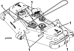
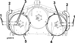
Remove the 6 hex-socket screws (5/16 x 3/4 inch) and 6 flange nuts (5/16 inch) plugging the exposed mounting holes in the deck (Figure 1).
Note: Retain these parts for future use.
-
Remove and retain the 2 rear carriage bolts (3/8 x 2-1/4 inches) and 2 flange nuts (3/8 inch) from each side within the cutting chamber securing the side bumpers to the deck sides.
Installing the Baffles
Parts needed for this procedure:
| Front, right baffle | 1 |
| Rear, right baffle | 1 |
| Front, center baffle | 1 |
| Rear, center baffle | 1 |
| Front, left baffle | 1 |
| Rear, left baffle | 1 |
| Right kicker baffle | 1 |
| Center kicker baffle | 1 |
| Left kicker baffle | 1 |
| Locknut (3/8 inch) | 2 |
| Carriage bolt (3/8 x 7/8 inch) | 14 |
| Flange nut (3/8 inch) | 16 |
Note: Determine the left and right sides of the machine from the normal operating position.
-
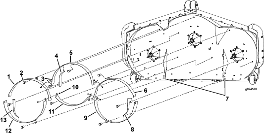
Install the front, outer baffles using 1 carriage bolt (3/8 x 7/8 inch) and 1 flange nut (3/8 inch) per baffle (Figure 2).
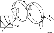
Note: To help align the baffles, loosely insert the carriage bolts (3/8 x 2-1/2 inches) and flange nuts (3/8 inch) through the side of the baffles and bumper (Figure 5).
-
Install the front, center baffle using 3 carriage bolts (3/8 x 7/8 inch) and 3 flange nuts (3/8 inch) as shown in Figure 2.
-
Install the rear, outer baffles using 1 carriage bolt (3/8 x 7/8 inch) and 1 flange nut (3/8 inch) per baffle Figure 2.
Note: To help align the baffles, loosely insert the carriage bolts (3/8 x 2-1/2 inches) and flange nuts (3/8 inch) through the side of the baffles and bumper (Figure 5).
Note: The front, outer baffles install between the rear baffle tabs.
-
Install the rear, center baffle using 2 carriage bolts (3/8 x 7/8 inch) and 2 locknuts (3/8 inch) as shown in Figure 3.
Note: This baffle installs between the front, outer baffle flanges (Figure 3).
Note: Where the front, outer baffles, the rear, outer baffles, and the rear, center baffle come together, install 2 carriage bolts (3/8 x 7/8 inch) and 2 locknuts (3/8 inch) as shown in Figure 3.
-
Tighten all the hardware.
-
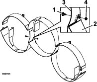
Install the correct kicker baffle to each chamber using 1 carriage bolt (3/8 x 7/8 inch) and 1 flange nut (3/8 inch) as shown in Figure 1.
Note: The hooked end of each kicker baffle attaches to the slot in the chamber baffle (Figure 4).
Note: You may need to loosen the mating baffle to allow the hooked end of the kicker baffle to fit correctly.
Securing the Bumpers and Right and Left Baffle to the Mower Deck
Parts needed for this procedure:
| Carriage bolt (3/8 x 2-1/2 inches) | 4 |
| Flange nut (3/8 inch) | 4 |
Note: To install the bumper bolts, you may need to loosen the mating baffle and kicker baffle.
Converting Back to Rear Discharge
-
Disengage the PTO, move the motion-control levers to the NEUTRAL-LOCK position, and engage the parking brake.
-
Shut off the engine, remove the key, and wait for all moving parts to stop before leaving the operating position.
-
Remove the finish-cut baffles and kicker baffles.
Retain all the hardware.
-
Replace the finish-cut blades with standard blades.
-
Install the hex-socket screws (5/16 x 3/4 inch) and the flange nuts (5/16 inch) in the holes on the top of the deck with the bolt head underneath.
Note: You must plug all open holes not covered by belt shields or the frame to prevent sand and/or other small objects from being thrown up through the deck.