Important: You cannot install the Utility Van Box on Lifted (LT) Models or a machine equipped with Lift Kit Model 07414.
You must install these kits with the Utility Van Box:
-
Canopy or Cab Kit
-
07921 — 2 Person Canopy Kit
-
07922 — 4 Person Canopy Kit or
-
07142 — Cab Kit
-
-
Door Mount Mirror Kit — Part No. 136-1997
-
Backup Alarm Kit
-
133-3018 — 12V Reverse Alarm Kit (Gas Machines) or
-
131-8549 — 48V Reverse Alarm Kit (Electric Machines)
-
Safety
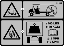
Safety and Instructional Decals
 |
Safety decals and instructions are easily visible to the operator and are located near any area of potential danger. Replace any decal that is damaged or missing. |
Installation
Important: Use 2 people when raising the utility van box onto the machine frame.
Preparing the Machine
-
Park the machine on a level surface.
-
Engage the parking brake.
-
Shut off the machine and remove the key.

Removing the Cargo Bed
-
Using an overhead hoist, raise the cargo bed.
-
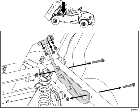
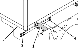
If applicable, remove the 2 bolts (3/8 x 2-1/2 inches), 2 flange nuts (3/8 inch), and 3 bolts (5/16 x 3/4 inch) from the prop rod assembly, and remove the prop rod assembly (Figure 2).
Note: Retain the hardware if you want to install the plastic cargo bed in the future.
-
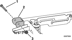
Remove the 2 pivot bolts (1/2 x 4-1/2 inches) and 2 locknuts (1/2 inch) from the pivot bracket located at the rear of the machine (Figure 3).
Note: Retain the hardware if you want to install the plastic cargo bed in the future.
-
Release the cargo-bed lever and remove the cargo bed using an overhead hoist.
-
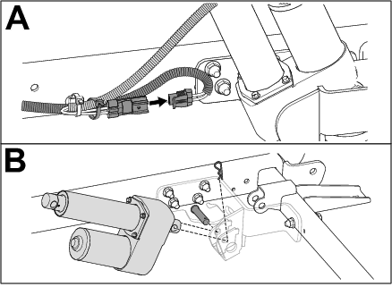
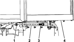
If applicable, remove the electric lift cylinder as shown in Figure 4.
-
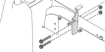
Remove the 2 latches, 4 flange-head bolts (3/8 x 2-1/2 inches), and 4 flange nuts (3/8 inch) from the left and right frame tubes (Figure 5).
Retain the fasteners for installation in Installing the Utility Van Box.
Reducing the Top Speed
Parts needed for this procedure:
| Clutch spacer | 1 |
Caution
The dust in the clutch will become airborne and could damage your eyes or you could inhale it, causing breathing difficulties.
Wear safety goggles and a dust mask or other eye and respiratory protection when performing this procedure.
-
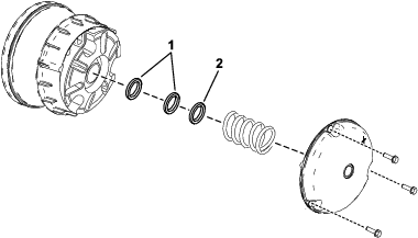
Remove the bolts securing the primary clutch cover as shown in Figure 6.
Important: Use caution when removing the clutch cover; the spring is under compression.
Important: Take note of the X orientation on the clutch covers and clutch assemblies for later installation.
-
Remove the spring.
-
Install the clutch spacer to reduce the top speed to 19 kph (12 mph).
Important: Do not operate the machine without at least 3 clutch spacers in place.
Spacers Top Speed 2 (standard) 26 kph (16 mph)—standard 3 19 kph (12 mph) -
Install the spring and clutch cover.
Important: Ensure that the X is placed back in the original location.
-
Torque the bolts to 179 to 228 N∙m (132 to 168 in-lb).
Installing the Utility Van Box
Parts needed for this procedure:
| Utility van box | 1 |
| Flange-head bolt (1/2 x 1-1/4 inches) | 2 |
| Flange nut (1/2 inch) | 2 |
Important: Use 2 people when raising the utility van box onto the machine frame.
-
Secure the front of the utility van box to the front of the frame tubes using the previously removed 2 flange-head bolts (3/8 x 2-1/2 inches) and 2 flange nuts (3/8 inch) on each side (Figure 7).
-
Torque the flange nuts (3/8 inch) to 37 to 45 N∙m (27 to 33 ft-lb).
-
Secure the rear of the utility van box to the rear of the frame tubes using a flange-head bolt (1/2 x 1-1/4 inches) and a flange nut (1/2 inch) on each side (Figure 8).
-
Torque the flange nuts (1/2 inch) to 92 to 112 N∙m (67.5 to 82.5 ft-lb).
Installing the Canopy or Cab Kit
Parts needed for this procedure:
| Canopy or cab kit — 07921, 07922, or 07142 (sold separately) | 1 |
Install the Canopy or Cab Kit; refer to the Installation Instructions for the kit.
Installing the Door Mount Mirror Kit
Parts needed for this procedure:
| Door Mount Mirror Kit — Part No. 136-1997(sold separately) | 1 |
Install the Door Mount Mirror Kit; refer to the Door Mount Mirror Kit Installation Instructions.
Installing the Backup Alarm Kit
Parts needed for this procedure:
| Backup Alarm Kit — Part No. 133-3018 for gas machines or 131-8549 for electric machines (sold separately). | 1 |
Install the Backup Alarm Kit; refer to the Backup Alarm Kit Installation Instructions.