


Maintenance
Recommended Maintenance Schedule(s)
| Maintenance Service Interval | Maintenance Procedure |
|---|---|
| After the first 2 hours |
|
| After the first 10 hours |
|
| Before each use or daily |
|
| Every 50 hours |
|
Caution
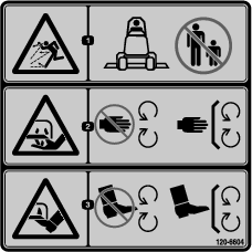
If you leave the key in the ignition switch, someone could accidentally start the engine and seriously injure you or other bystanders.
Remove the key from the ignition switch before you perform any maintenance.
Warning
If you raise the machine using only a jack to support it while you work under the mower deck, the jack could tip, causing the mower deck to fall, crushing you or bystanders.
Always secure the machine with at least 2 jack stands when you have the mower deck raised.
Caution
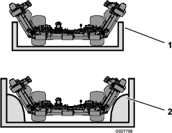
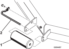
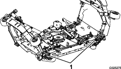
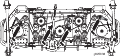
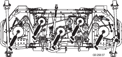
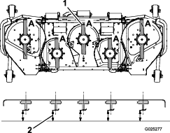
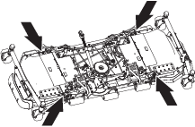
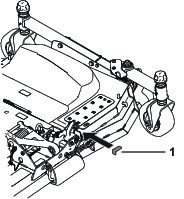
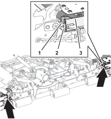
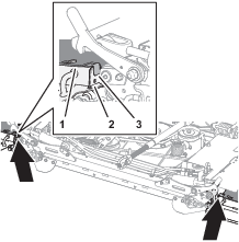
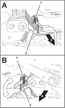
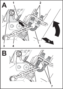
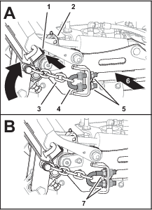
On the top of the mower deck are 2 links that connect them to the frame. Connected to these links are torsion springs that are under tension (Figure 14). If you disconnect the link, the stored energy in the torsion spring will be released and could cause the links to move, damaging your hands or fingers.
Be careful when removing the mower deck from the frame and secure the links before disconnecting them from the frame.
Lubrication
| Maintenance Service Interval | Maintenance Procedure |
|---|---|
| Before each use or daily |
|
| Every 50 hours |
|
The machine has grease fittings that must be lubricated regularly with No. 2 lithium grease. If the machine is operated under normal conditions, lubricate all bearings and bushings after every 50 hours of operation or immediately after every washing.
Lubricate the following areas:
Servicing the Drive Belts
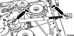
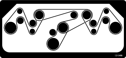
Refer to Figure 22 for routing the drive belts appropriately.
Servicing the Bushings in the Caster Arms
The caster arms have bushings pressed into the top and bottom of the tube and after many hours of operation, the bushings wear. To check the bushings, move the caster fork back and forth and from side to side. If the caster spindle is loose inside the bushings, the bushings are worn; replace them.
-
Raise the cutting unit so that the wheels are off the floor. Block the cutting unit so that it cannot accidentally fall.
-
Remove the tensioning cap, spacer(s), and thrust washer from the top of the caster spindle.
-
Pull the caster spindle out of the mounting tube. Allow the thrust washer and spacer(s) to remain on the bottom of the spindle.
-
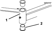
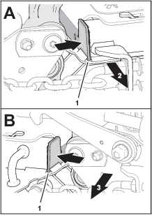
Insert a pin punch into the top or bottom of the mounting tube and drive the bushing out of the tube (Figure 23).
-
Drive the other bushing out of the tube.
-
Clean the inside of the tubes to remove any dirt.
-
Apply grease to the inside and outside of the new bushings.
-
Using a hammer and a flat plate, drive the bushings into the mounting tube.
-
Inspect the caster spindle for wear and replace it if it is damaged.
-
Push the caster spindle through the bushings and the mounting tube.
-
Slide the thrust washer and the spacer(s) onto the spindle.
-
Install the tensioning cap on the caster spindle to retain all parts in place.
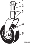
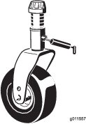
Servicing the Caster Wheels and Bearings
| Maintenance Service Interval | Maintenance Procedure |
|---|---|
| After the first 2 hours |
|
| After the first 10 hours |
|
| Every 50 hours |
|
-
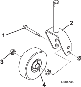
Remove the locknut from the bolt holding the caster wheel assembly between the caster fork (Figure 24).
-
Grasp the caster wheel and slide the bolt out of the fork or pivot arm.
-
Remove the bearing from the wheel hub and allow the bearing spacer to fall out (Figure 24).
-
Remove the bearing from the opposite side of the wheel hub.
-
Check the bearings, spacer, and inside of the wheel hub for wear. Replace any damaged parts.
-
To assemble the caster wheel, push the bearing into the wheel hub.
Note: When installing the bearings, press on the outer race of the bearing.
-
Slide the bearing spacer into the wheel hub. Push the other bearing into the open end of the wheel hub to captivate the bearing spacer inside the wheel hub.
-
Install the caster wheel assembly between the caster fork and secure it in place with the bolt and locknut.
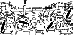
Servicing the Blades
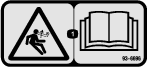
Maintain sharp blades throughout the cutting season because sharp blades cut cleanly without tearing or shredding the grass blades. Tearing and shredding turns grass brown at the edges, which slows growth and increases the chance of disease.
Check the blades daily for sharpness, and for any wear or damage. Sharpen the blades as necessary. If a blade is damaged or worn, replace it immediately with a genuine Toro replacement blade.
Danger
A worn or damaged blade can break, and a piece of the blade could be thrown toward you or a bystander, resulting in serious personal injury or death.
-
Inspect the blade periodically for wear or damage.
-
Replace a worn or damaged blade.
Inspect and check the blades every 8 hours.
Before Inspecting or Servicing the Blades
-
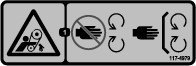
Disengage the PTO, release the traction pedal, and engage the parking brake.
-
Move the throttle lever to the SLOW position, stop the engine, remove the key, and wait for all moving parts to stop before leaving the operating position.
Inspecting the Blades
| Maintenance Service Interval | Maintenance Procedure |
|---|---|
| Before each use or daily |
|
-
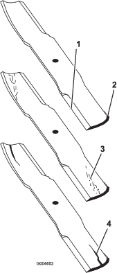
Inspect the cutting edges (Figure 25). If the edges are not sharp or have nicks, remove and sharpen the blades. Refer to Sharpening the Blades.
-
Inspect the blades, especially the sail area (Figure 25). If you notice any damage, wear, or a slot forming in this area (Figure 25), immediately install a new blade.
Danger
If you allow the blade to wear, a slot will form between the sail and flat part of the blade. Eventually a piece of the blade may break off and be thrown from under the housing, possibly resulting in serious injury or death to you or bystanders.
-
Inspect the blade periodically for wear or damage.
-
Never try to straighten a blade that is bent or weld a broken or cracked blade.
-
Replace a worn or damaged blade.
-
Checking for Bent Blades
-
Disengage the PTO, release the traction pedal and engage the parking brake.
-
Move the throttle lever to the SLOW position, shut off the engine, remove the key, and wait for all moving parts to stop before leaving the operating position.
-
Rotate the blades until the ends face forward and backward (Figure 26).
-
Measure from a level surface to the cutting edge, position A, of the blades (Figure 26). Note this dimension.
-
Rotate the opposite ends of the blades forward.
-
Measure from a level surface to the cutting edge of the blades at the same position as in step 3 above. The difference between the dimensions obtained in steps 3 and 4 must not exceed 3 mm (1/8 inch). If this dimension exceeds 3 mm (1/8 inch), the blade is bent and must be replaced; refer to Removing the Blades and Installing the Blades.
Warning
A blade that is bent or damaged could break apart and could seriously injure or kill you or bystanders.
-
Always replace bent or damaged blade with a new blade.
-
Never file or create sharp notches in the edges or surfaces of blade.
-
Removing the Blades
A blade must be replaced if it is out of balance, bent, or if it is hit by a solid object. To ensure optimum performance and continued safety conformance of the machine, use genuine Toro replacement blades. Replacement blades made by other manufacturers may result in non-conformance with safety standards.
Warning
Contact with a sharp blade can cause serious injury.
Wear gloves or wrap sharp edges of the blade with a rag.
-
Hold the blade end using a rag or a thickly-padded glove.
-
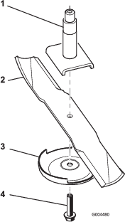
Remove the blade bolt, the anti-scalp plate, and the blade from the spindle shaft (Figure 29).
Sharpening the Blades
Warning
When sharpening blade, pieces of blade could be thrown and cause serious injury.
Wear proper eye protection when sharpening blades.
-
Sharpen the cutting edge at both ends of the blade (Figure 27).
Note: Maintain the original angle. The blade retains its balance if the same amount of material is removed from both cutting edges.
-
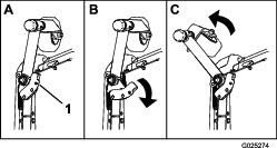
Check the balance of the blade by putting it on a blade balancer (Figure 28).
Note: If the blade stays in a horizontal position, the blade is balanced and can be used. If the blade is not balanced, file some metal off the end of the sail area only (Figure 29). Repeat this procedure until the blade is balanced.

Installing the Blades
Note: The 2 wing-deck blades are not the same as the 3 center blades.
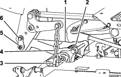
Adjusting the Deck-Limit Chains
Use 2 deck shims Toro Part No. 138-8243 or 2 feeler gauges—0.15 mm (0.060 inch)
Preparing the Deck
-
Start the engine, lower the left and right decks, shut off the engine, remove the key, and wait for all moving parts to stop.
-
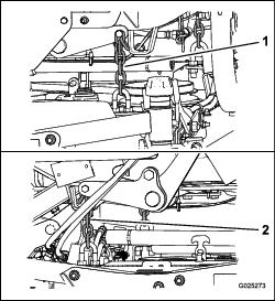
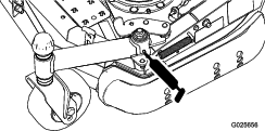
At the outer decks, wipe clean the tab of the inner channel (Figure 30).
-
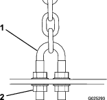
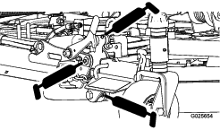
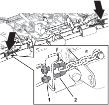
At the front of the deck, fully loosen the outboard serrated-flange nuts securing the 4 U-bolts (Figure 31).
-
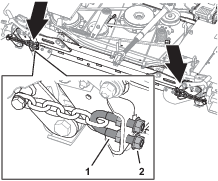
At the back of the deck, fully loosen the inboard serrated-flange nuts securing the 4 U-bolts (Figure 32).
Assembling the Shim to the Deck
-
Install the deck shims at the front of the deck as shown in Figure 33.
Note: Insert the part of the long tab of the shim under the belt cover.
-
Install the deck shims at the front of the deck as shown in Figure 34.
Note: If you are using feeler gauges, use a piece of tape to adhere a feeler gauge—0.15 mm (0.060 inch) to the tab of the inner channel (Figure 35).
-
Start the engine, fully raise the left and right decks, shut off the engine, remove the key, and wait for all moving parts to stop.
Tensioning the Chains
-
At the front of the deck, tighten the outboard serrated-flange nuts until the chains are tensioned (Figure 36).
Note: Ensure that the deck shim (or feeler gauge) contacts then pivot link.
Important: Ensure that the upper and lower serrated-flange nut pairs are adjusted evenly.
-
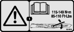
Thread the inboard serrated-flange nuts (Figure 36) and torque them to 103 to 127 N∙m (76 to 94 ft-lb).
-
At the back of the deck, tighten the inboard serrated-flange nuts until the chains are tensioned (Figure 37).
Note: Ensure that the deck shim (or feeler gauge) contacts then pivot link.
Important: Ensure that the upper and lower serrated-flange nut pairs are adjusted evenly.
-
Thread the outboard serrated-flange nuts (Figure 37) and torque them to 103 to 127 N∙m (76 to 94 ft-lb).
-
Start the engine, lower adjusted deck, raise the other deck, shut off the engine, remove the key, and wait for all moving parts to stop.
-
Remove the shims or feeler gauges (Figure 38).
-
Repeat steps in Assembling the Shim to the Deck and Tensioning the Chains for the other mower deck.