Safety
Safety and Instructional Decals
 |
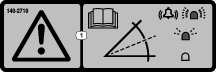
Safety decals and instructions are easily visible to the operator and are located near any area of potential danger. Replace any decal that is damaged or missing. |
Installation
Note: Determine the left and right sides of the machine from the normal operating position.
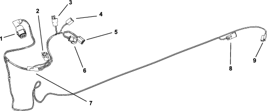
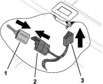
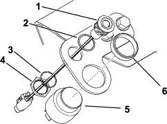
Refer to Figure 1 to identify the connectors on the wire harness.
Preparing the Machine
-
Park the machine on a level surface.
-
Disengage the blade-control switch.
-
Move the motion-control levers outward to the NEUTRAL-LOCK position.
-
Engage the parking brake (if applicable).
-
Shut off the engine and remove the key.
-
Raise the rear of the machine and support it using jack stands rated for your machine.
Warning
Mechanical or hydraulic jacks may fail to support the machine and cause serious injury.
Use jack stands when supporting the machine.
-
Raise the seat.
-
Disconnect the battery. Disconnect the negative terminal first and the positive last.
Note: When connecting the battery after installing the kit, connect the positive terminal first and the negative last.
Installing the Kit
Parts needed for this procedure:
| Sensor module | 1 |
| Bolt | 2 |
| Nut | 2 |
| Wire harness | 1 |
| Flat light bracket (machines without suspension system only) | 1 |
| Bent light bracket (machines with suspension system only) | 1 |
| Self-tapping screw | 2 |
| Alarm | 1 |
| LED light | 1 |
| Magnet | 4 |
Installing the Sensor Module
-
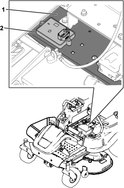
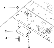
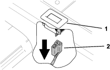
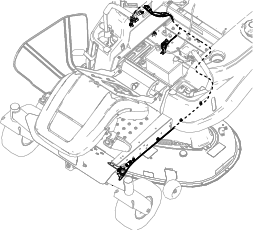
Place the sensor module on a flat surface on the right side of the crossmember frame, toward the control pane (Figure 2). Mark the locations of the 2 holes.
Note: You may use existing holes in the frame and drill fewer holes.
-
Remove the sensor module and drill the 2 holes (7 mm or 9/32 inch).
-
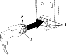
Connect the slope sensor connector from the wire harness to the sensor module.
Important: Ensure that the tabs on the slope sensor connector align with the slots in the sensor module.
-
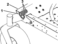
Install the sensor module under the crossmember frame using 2 bolts and 2 nuts (Figure 4).
Connecting the Wire Harness in the Control Panel
-
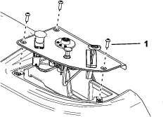
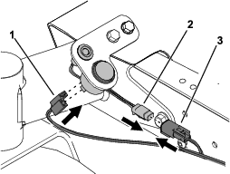
Remove the 3 screws securing the control panel, then remove the lift the control panel to access the wire harness (Figure 5).
-
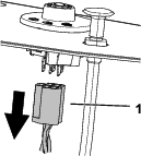
Disconnect the wire harness from the key switch (Figure 6).
-
Connect the key switch “in” connector from the kit wire harness to the key switch (Figure 7).
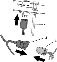
-
Connect the key switch “out” connector to the key switch connector from the machine wire harness (Figure 7).
Connecting the Hour Meter Connectors
For machines without a hour meter, skip to step 3.
Note: Figures show machines with the hour meter located behind the seat. The hour meter for machines with a suspension system is located on the control panel.
-
Disconnect the machine hour meter connector from the hour meter (Figure 8).
-
Connect the hour meter “in” connector from the kit wire harness to the hour meter.
-
Connect the hour meter “out” connector from the kit wire harness to the hour meter connector from the machine wire harness (Figure 9).
Note: For machines without a hour meter, the hour meter connector is taped to the main wire harness.
-
Install the control panel and secure it with the 3 screws previously removed (Figure 5).
Installing the LED Light and Alarm
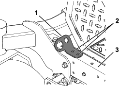
For machines with a suspension system, use the bent light bracket. For machines without a suspension system, use the flat light bracket.
-
Use the light bracket as a template, and drill 2 holes (7 mm or 9/32 inch).
For machines with a suspension system, drill the holes into the frame rail, toward the front (Figure 10).
For machines without a suspension system, drill the holes into the left side of the footrest (Figure 11).
-
Secure the bracket to the machine using 2 self-tapping screws.
-
Remove the plastic nut from the alarm and use it to install the alarm to the bracket (Figure 12).
-
Remove the nut, lock washer, and gasket from the LED light and use them to install the light to the bracket (Figure 12).
Routing the Wire Harness to the Light and Alarm
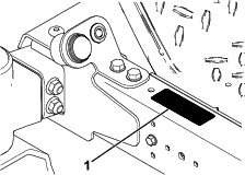
Installing the Decal
Calibrating the Sensor
-
While on a flat surface, remove the plug from calibration connectors.
Note: The plugs are located between the hour meter and key connectors.
-
Plug the connectors together.
-
Turn the ignition key to the ON position, but do not start the engine.
Note: The LED light blinks as the sensor calibrates.
-
When the light no longer blinks, turn the ignition key to the OFF position.
-
Disconnect the calibration connectors and install the plug onto the connectors.
-
Lower the seat.
Operation
Using the Slope Sensor
When you start the machine, the LED light illuminates for 5 seconds to indicate that the sensor is functioning properly.
The light and alarm indicates the severity of the slope:
-
No light—normal operating conditions
-
Slow, flashing light—moderate slope
-
Fast, flashing light and audible alarm—steep slope; proceed to a more shallow slope.
Warning
Slopes are a major factor related to loss-of-control and tip-over accidents, which can result in severe injury or death.
Use extreme caution when operating the machine on a slope.