Read this information carefully to learn how to operate and maintain your product properly and to avoid injury and product damage. You are responsible for operating the product properly and safely.

Whenever you need service, genuine Toro parts, or additional information, contact an Authorized Service Dealer or Toro Customer Service and have the model and serial numbers of your product ready.

You may contact Toro directly at www.Toro.com for product safety and operation training materials, accessory information, help finding a dealer, or to register your product.

Introduction

The Software Guide for the Multi Pro 5800-D and 5800-G Turf Sprayer with ExcelaRate Spray System provides information for using sprayer system information and control sprayer system functions.

Setup

Before You Begin Spraying

Preparing the Machine when Spraying in the Application Rate Mode

  1. Fill the sprayer tank and fresh water tank; refer to filling the spray tank and filling the fresh-water tank procedures in the Operator’s Manual.

  2. Calibrate the sprayer system; refer to Calibrating the Sprayer.

  3. Set the application rate value(s) and active application rate for the sprayer job; refer to Setting the Rate 1 or Rate 2 Value and Setting the Active Rate.

  4. As needed, configure the following optional settings:

Preparing the Machine when Spraying in the Manual Mode

  1. Fill the sprayer tank and fresh water tank; refer to filling the spray tank and filling the fresh-water tank procedures in the Operator’s Manual.

  2. As needed, configure the following optional settings:

Product Overview

InfoCenter Home Screen

When you start the machine, the home screen appears, displaying the corresponding icons that apply (i.e., the parking brake is engaged, the sprayer sections are on, you are out of the seat, etc.).

Note: The following figure is an example screen; this screen shows all the potential icons that could appear on the screen while operating.

Refer to the following graphic for all of the icon definitions (Figure 1).

g191986

Master-Section Indicator

The master-section indicator displays when the master section switch is in the ON position (Figure 1).

Sprayer-Section Indicators

The left, right, and/or center sprayer sections display when any of the sprayer-section switches are in the ON position (Figure 1).

Active-Application Rate

The active-application rate indicates the actual rate at which the sprayed product is being applied (Figure 1).

Target-Application Rate (Application Rate Mode Only)

The target-application rate indicates the target rate that the user set (Figure 1).

Note: In application-rate mode, the system attempts to attain the target rate that you set.

Vehicle-Speed Indicator

The vehicle-speed indicator displays the current vehicle speed (Figure 1).

System-Pressure Indicator

When sprayer sections are active (on), the system-pressure indicator displays the spray pressure; when the sprayer sections are off, the agitation pre-set pressure displays (Figure 1).

Parking-Brake Indicator

The parking-brake indicator displays on the Home Screen when the parking brake is engaged (Figure 1).

Operator’s-Seat Indicator

The operator-seat indicator displays on the Home Screen when the operator is out of the seat (Figure 1).

Active-Application Rate/Boost-Rate Indicator (Application Rate Mode Only)

The active-application rate indicator displays which preset application rate you are using (Figure 1). The boost-rate indicator displays when you press and hold buttons 1 and 5 simultaneously to apply a boosted application rate, such as boosting the application rate when spraying herbicide over a patch of weeds.

Spray-Pump Indicator

The spray-pump indicator displays when the spray pump is running (Figure 1).

Rinse-System Indicator

Optional Kit

The rinse-system indicator displays when the rinse system is active (Figure 1).

Agitation Indicator

The agitation indicator displays when the agitation valve is open (Figure 1).

Operation

Before Operation

Accessing the Main Menu Screen

From the Home screen, press and hold the button 5 (far right) on the InfoCenter to access the MAIN MENU screen (Figure 2).

g193013

From the main menu screen, you can access the Set Rates screen, Settings screen, Calibration screen, Service screen, Diagnostics screen, or the About screen (Figure 3).

g193014

InfoCenter Main Sub Menus

Set Rates Screen (Application Rate Mode Only)

  1. To access the set rates screen, press button 2 on the MAIN MENU screen to navigate to the SET RATES option (Figure 4).

    g191808
  2. Press button 4 to select SET RATES sub-menu (Figure 4).

This screen displays and allows you to set the Active (application) Rate, Rate 1, Rate 2, and the Boost-rate percentage.

Setting the Active Rate

Use the active rates option to set the sprayer preset rate to either rate 1 or rate 2.

  1. Press button 1 or 2 to navigate to the ACTIVE RATE option (Figure 5).

    g191729
  2. Press button 4 to select the ACTIVE RATE entry (Figure 5).

  3. Press buttons 3 or 4 to set the programmed active rate to either RATE 1 or RATE 2 (Figure 5).

  4. Press button 5 to save the setting, exit the RATES screen, and return to the Main screen.

Note: When you are spraying you can quickly switch the active rate between the rate 1 value and the rate 2 value from the home screen. Press buttons 1 and 2 simultaneously to select RATE 1 or press buttons 4 and 5 simultaneously to select RATE 2.

Setting the Rate 1 or Rate 2 Value

  1. Press button 1 or 2 to navigate to the RATE 1 or RATE 2 options (Figure 6).

    g191782
  2. Press button 4 to select the sprayer RATE option (Figure 6).

  3. Press buttons 3 or 4 to set the raise or lower the sprayer rate (Figure 7).

    Note: You can change the rate faster by pressing and holding button 3 or 4.

    g191794
  4. Press button 5 to save the setting, exit the RATE screen, and return to the SET RATES screen.

Setting the Boost Percentage

The boost rate % is the percentage amount added to the active rate when you want to spray additional chemical to a turf area, such as additional herbicide sprayed at an area of weeds.

Note: While using the sprayer, at the Home screen press and hold buttons 1 and 5 simultaneously to apply boost rate.Boost is active only as long as you hold buttons 1 and 5, then returns the set rate when you no longer press and hold the buttons.

  1. Press button 1 or 2 to navigate to the boost-rate percentage option (Figure 8).

    g191781
  2. Press button 4 to select the Boost % setting (Figure 9).

    Note: You can set the boost percentage to 5%, 10%, 15%, 20%, or 25% increments.

    g191807
  3. Press button 3 or 4 to raise or lower the boost percentage (Figure 9).

    Note: Examples—if boost %=25%, while boost rate is activated the sprayer volume is 125% of the active rate.

  4. Press button 5 to save the BOOST %, exit the boost screen, and return to the SET RATES screen.

Settings

  1. To access the SETTINGS screen, press button 2 on the MAIN MENU screen to navigate to the Settings option (Figure 10).

    g192022
  2. Press button 4 to select SETTINGS sub-menu (Figure 10).

    Note: This screen displays and allows you to set the Tank, Display, Boom Width, Reset Defaults, and GeoLink settings.

Tank Settings

  1. Press button 1 or 2 to navigate to the TANK option (Figure 11).

    g191832
  2. Press button 4 to select TANK sub-menu (Figure 11).

This screen displays and allows you to set the Tank Volume, Low Limit, Low Limit Volume, and Preset Agitation settings.

Setting the Tank Volume

  1. Press button 1 or 2 to navigate to the TANK VOLUME option (Figure 12).

    g191833
  2. Press button 3 or 4 to raise or lower the value for the volume of chemical in the sprayer tank (Figure 12).

  3. Press button 5 to save the setting, exit the TANK screen, and return to the SETTINGS screen.

Setting the Low Limit Indicator

  1. Press button 1 or 2 to navigate to the LOW LIMIT option (Figure 13).

    g191831
  2. Press button 4 to turn on or turn off the limit indicator for the low tank volume (Figure 13).

  3. Press button 5 to save the setting, exit the TANK screen, and return to the SETTINGS screen.

Setting the Low Limit Volume Value

  1. Press button 1 or 2 to navigate to the LOW LIMIT volume option (Figure 14).

    g191829
  2. Press button 4 to select the LOW LIMIT volume entry (Figure 14).

  3. Press button 3 or 4 to raise or lower the threshold volume at which the limit indicator displays in the InfoCenter (Figure 14).

  4. Press button 5 to save the setting, exit the TANK screen, and return to the SETTINGS screen.

Setting the Preset Agitation Value (Application Rate Mode Only)

Note: The preset agitation setting is used to set the sprayer pump speed when the sprayer is operated in the Application Rate Mode with all sprayer section shut off. The preset agitation setting controls the percentage of sprayer pump speed. The default preset agitation setting is 40%.

  1. Identify the target sprayer pressure that you are planning to spray—for example: 2.76 bar (40 psi). Record the pressure displayed on the dash mounted sprayer-pressure gauge below.

    Sprayer pressure:
  2. Calculate the initial agitation preset pressure using the formula below:

    Sprayer operation pressure x 1.5 to 2.0 = initial agitation preset pressure
    Example: target sprayer pressure 2.76 bar (40 psi) x 1.5 = initial agitation preset pressure 4.1 (60 psi)Example: target sprayer pressure 2.76 bar (40 psi) x 2.0 = initial agitation preset pressure 5.5 bar (80 psi)
    Record your calculation here:
  3. With the master section switch in the OFF position and the engine throttle set to the engine speed you intend to run the machine, adjust the preset agitation value until the sprayer system pressure is between 1.5 to 2.0 times the target sprayer pressure that you identified in step 1.

    For example, if you are spraying at 2.76 bar (40 psi), initially set Preset Agitation to achieve a system pressure of 4.1 to 5.5 bar (60 to 80 psi).

    Note: If the chemicals in the sprayer tank are foaming, lower the preset agitation value as necessary to reduce system pressure when tank agitation is running.

  4. Press button 1 or 2 to navigate to the AGITATION option (Figure 15).

    g191830
  5. Press button 4 to select the AGITATION entry (Figure 15).

  6. While watching the dash mounted sprayer-pressure gauge, press button 3 or 4 to raise or lower the preset value until the sprayer pressure is at the initial agitation preset pressure that you calculated in step 2 (Figure 15).

    Note: Do not exceed 586 kPa (85 psi) sprayer system pressure when adjusting the preset agitation value.

    Note: You may set the preset agitation value higher if agitation does not cause the chemical in the tank to foam. You may need to lower the agitation value if agitation causes the chemical in the tank to foam.

  7. Press button 5 to save the setting, exit the TANK screen, and return to the SETTINGS screen.

Display Settings

  1. Press button 1 or 2 to navigate to the DISPLAY option (Figure 16).

    g191894
  2. Press button 4 to select DISPLAY sub-menu (Figure 16).

Note: This screen displays and allows you to set the Units of Measure, Language, Backlighting, Contrast, Protection for Menus, PIN Settings, and audio Mute settings.

Setting Units of Measure

  1. Press buttons 1 or 2 to navigate to the UNITS option (Figure 17).

    g191891
  2. Press button 4 to switch between ENGLISH, TURF, and SI units of measure (Figure 17).

    • English: mph, gallons, acre

    • Turf: mph, gallons, 1000 ft²

    • SI (metric): kph, liter, hectare

    Note: Changing the units of measure setting clears the tank volume entry and the preset Rate 1 and Rate 2 settings.

  3. Press button 5 to save the setting, exit the UNITS screen, and return to the Settings screen (Figure 17).

Setting the Display Language

  1. Press buttons 1 or 2 to navigate to the LANGUAGE option (Figure 18).

    g191895
  2. Press button 4 to select the LANGUAGE entry (Figure 18).

  3. Press buttons 1 or 2 to navigate to the language to which you want the InfoCenter to display (Figure 19).

    g191892
  4. Press button 4 to select the language (Figure 19).

  5. Press button 5 to save the setting, exit the LANGUAGE screen, and return to the DISPLAY screen (Figure 19).

Setting the Display Backlighting or Contrast

  1. Press buttons 1 or 2 to navigate to the BACKLIGHT or the CONTRAST option (Figure 20).

    g191898g191899
  2. Press button 4 to select the BACKLIGHTING or CONTRAST entry (Figure 20).

  3. Press buttons 3 or 4 to set the desired display backlighting or contrast value (Figure 20).

    Note: The backlighting intensity or contrast changes on the display of the InfoCenter as you change the value for the setting.

  4. Press button 5 to save the setting, exit the BACKLIGHT or the CONTRAST screen, and return to the SETTINGS screen (Figure 20).

Setting Protection for Menus

Note: Refer to Changing PIN Settings—Assessing the PIN Settings Sub-menu for related information.

  1. Press buttons 1 or 2 to navigate to the PROTECTED MENUS option (Figure 21).

    g191896
  2. Press button 4 to select the PROTECTED MENUS entry (Figure 21).

  3. Press buttons 1 or 2 to navigate to the menu option that you want to change PIN code protection (Figure 22).

    g191893
  4. Press button 4 to select the menu option (Figure 22).

  5. Repeat steps 3 and 4 for any other menus that you want to change PIN code protection.

  6. Press button 5 to save the setting, exit the PROTECTED MENUS screen, and return to the DISPLAY screen (Figure 22).

Changing PIN Settings—Assessing the PIN Settings Sub-menu

  1. Press buttons 1 or 2 on the DISPLAY screen to navigate to the PIN SETTINGS option (Figure 23).

    g034290
  2. Press button 4 to select PIN SETTINGS sub-menu (Figure 23).

  3. Press buttons 1 through 4 to enter your PIN code. When you complete entering the PIN, press button 5 (Figure 24).

    Note: Each time you press the same button to enter a PIN digit, the number increases in value.

    g034292

Changing PIN Settings—Setting PIN Entry Requirements

  1. Press buttons 1 or 2 to select the PIN ENTRY option (Figure 25).

    g034291
  2. Press button 4 to turn the PIN requirement ON or OFF (Figure 25).

  3. Press button 5 to save the setting, exit the PIN SETTINGS screen, and return to the DISPLAY screen.

Changing PIN Settings—Changing the PIN Code

  1. Press buttons 1 or 2 to select the PIN CHANGE option (Figure 26).

    g034303
  2. Press button 4 to select the PIN CHANGE entry (Figure 26).

  3. Press buttons 1 through 4 to enter your PIN code. When you complete entering the PIN, press button 5 (Figure 24).

    Note: Each time you press the same button to enter a PIN digit, the number increases in value.

  4. At the enter old PIN screen, press buttons 1 through 4 to enter your old PIN code, and press button 5 when you complete the PIN (Figure 24).

    Note: The default PIN code when you initially create your PIN is 1234.

    g034306
  5. At the enter new PIN screen, press buttons 1 through 4 to enter your new PIN code. When you complete entering the PIN, press button 5 (Figure 28).

    g034307
  6. At the conform screen, press buttons 1 through 4 to enter your new PIN code. When you complete entering the PIN, press button 5 (Figure 29).

    g034308

    Note: After you confirm the pin code (Figure 29), the Pin Correct screen appears for approximately 5 seconds.

Muting the Audio Indicator

Note: Setting the mute audio indicator to On mutes the audio signal for the InfoCenter only—not the audio warning for the machine.

  1. Press buttons 1 or 2 to navigate to the MUTE option (Figure 30).

    g191890
  2. Press button 4 to turn the audio indicator ON or OFF (Figure 31).

    g191889
  3. Press button 5 to save the setting, exit the MUTE screen, and return to the SETTINGS screen (Figure 31).

Setting the Boom Widths

The boom-width settings are pre-populated at the manufacturing plant.

  1. Press button 2 on the Settings screen until you reach the BOOM WIDTH option (Figure 32).

    g191711
  2. Press button 4 to select the BOOM WIDTHS entry (Figure 32).

  3. Press button 2 to select the boom section that you want to edit the width (Figure 33).

    g224287
  4. Press button 3 or button 4 to lower or raise the boom width value (Figure 33).

  5. Press button 5 to save your settings and exit the BOOM WIDTH screen, and return to the SETTINGS screen (Figure 33).

Resetting the Default Settings

  1. Press button 2 on the SETTINGS screen until you reach the RESET DEFAULTS option (Figure 34).

    g191706
  2. Press button 4 to select the RESET DEFAULTS entry (Figure 34).

  3. Press button 1 or 2 to select 1 of the following options that you want to reset to factory setting:

    • Display

    • Flow Calibration

    • Speed Calibration

    • All Others

    g191707
  4. Press button 4 to reset the settings for the selected option (Figure 35).

  5. Repeat steps 3 and 4 for other options that you want to reset (Figure 35).

  6. Press button 5 to save your settings and exit the RESET DEFAULTS screen, and return to the SETTINGS screen (Figure 35).

Setting the GeoLink Option

  1. Press button 1 or 2 on the SETTINGS screen until you reach the GEOLINK option (Figure 36).

    g191703
  2. Press button 4 to select the GeoLink entry (Figure 36).

  3. On the GeoLink menu, press button 4 to select the Yes option or press button 4 to select the No option, and press the button 5 to save your settings and exit the menu (Figure 37).

    Note: Turn on the GeoLink setting only if you have the optional GeoLink system installed on the machine.

    g191701g191700
  4. Rotate the ignition switch to the OFF position and then to the ON position (Figure 37).

    g191705
  5. Press button 5 to save your settings and exit the GEOLINK screen, and return to the SETTINGS screen (Figure 38).

Calibrating the Sprayer

Application Rate Mode

Note: To calibrate the sprayer for manual mode operation, refer to setting the section—bypass valves in the Operator’s Manual for the machine.

  1. Ensure that the sprayer tank is clean; refer to Cleaning the Sprayer System in the Operator’s Manual.

  2. To access the Calibration screen press buttons 1 or 2 on the MAIN MENU screen to navigate to the CALIBRATION option (Figure 39).

    g192024
  3. Press button 4 to select Calibration sub-menu (Figure 39).

    Note: This screen displays and allows you to calibrate the flow meter input, calibrate the speed sensor input, perform a speed test, and manually enter calculation data.

Flow Calibration

Customer provided equipment: Use a catch container graduated for the nozzle-flow rate as follows:

  • 1.5 Lpm (0.4 gpm) or less - a container graduated in 10 ml (1/2 oz) increments is preferred.

  • 1.9 Lpm (0.5 gpm) or more - a container graduated in 20 ml (1 oz) increments.

Important: You must perform a flow calibration for 3 sprayer sections each time you replace all nozzles, change to the active spray (down) position, or after replacing the flow meter. You should perform a flow calibration for 3 sprayer sections if you replace several worn nozzles.

Note: Incorrectly performing the catch test results in inaccuracy in flow calibration. The result of these inaccuracies causes the sprayer system to over-apply or under-apply sprayer chemicals.

Evaluating the Which Type of Flow Calibration to Perform

Use the Sprayer Sections Table to help determine how you typically spray turf with the machine and which flow calibration to perform.

Note: You can perform a combination of up to 3 flow calibration types.

Sprayer Section Table

 Perform the 3-boom calibration
3 sprayer sectionsYes
 
I also spray with 2 sprayer sections:Perform the 2-Boom Calibration 
Left and Center sections (OR)YesNo
Right and Center sections (OR)YesNo
Right and Left sectionsYesNo
 
I also spray with 1 sprayer section:Perform the 1-Boom Calibration 
Left sprayer section only (OR)YesNo
Center sprayer section only (Or)YesNo
Right sprayer section onlyYesNo

3 boom calibration: Always perform the calibration for the 3 sprayer sections when you change the nozzles to increase or decrease the range of application rates.

Note: If you do not perform the optional 2 boom calibration or 1 boom calibration, the sprayer uses the calculations from the 3-boom calibration in all sprayer-section combinations.

Optional 2 boom calibration: Calibrate the left and center sprayer sections or the right and center sprayer sections or the left and right sections if you typically spray with those section combinations. Perform this optional calibration after performing the 3 sprayer section calibration.

Note: The calibration you perform for two sprayer sections is used whenever you spray with any combination of 2 sprayer sections.

Note: You can only calibrate for 1 pair of sprayer sections for the 2 boom calibration. Calibrate from the pair of sprayer sections that you use the most. The sprayer system uses the 2-boom calculation when you spray with either the left and center or right and center section combinations.

Optional 1 boom calibration: Calibrate the left or center or right sprayer section if you typically spray with 1 sprayer section. Perform this optional calibration after performing the 3-sprayer-section calibration and 2-sprayer-section calibration.

Note: You can only calibrate 1 of the 3 sprayer sections for the 1 boom calibration. Calibrate from the sprayer section that you use the most. The sprayer system uses the 1-boom calibration when you spray with the left, center, or right section.

Preparing for the Flow Test

  1. Ensure that the nozzles that you intend to use are in the active spray (down) position (Figure 40).

    Important: All nozzles in the active position must be the same color.

    Note: For best results, nozzles in the active position should have approximately the same amount of wear.

    g192604
  2. Press buttons 1 or 2 on the CALIBRATION sub-menu to navigate to the FLOW option (Figure 41).

    g192583
  3. Press button 4 to select Flow calibration option (Figure 41).

  4. Fill the sprayer tank half full—600 L or 150 US gal of water (Figure 42).

    Note: You can cancel the flow calibration by pressing button 5. A message displays confirming that you canceled the flow calibration.

    g192582
  5. Engage the parking brake (Figure 42).

  6. Start the engine and lower the outer sections.

  7. Set the pump switch to the ON position (Figure 43).

    g192636
  8. Move the throttle to the FAST position (Figure 43) and allow the engine to run for 10 minutes.

    Important: You must bring the hydraulic system to operating temperature before proceeding with the remaining flow calibration steps.

Preparing for the Catch Test

  1. Press button 2 to advance to the next step (Figure 42).

  2. Press buttons 3 or 4 to select the nozzles installed at the active spray position as follows:

    • For machines with nozzle colors that match the flow rates described in Figure 44, select the color of nozzles installed at the active spray position.

    • For machines with nozzle colors that do not match the flow rates described in Figure 44, select the flow rate (gpm or lpm) of nozzles installed at the active spray position.

    g192605
  3. Press button 2 to advance to the next step (Figure 44).

  4. Set the sprayer mode switch to the manual position (Figure 45).

    g192606g192608
  5. Rotate the knob for the section-bypass shutoff valve to the closed position (Figure 45).

    g192607
  6. Set the agitation switch to the OFF position and set the throttle to the FAST position (Figure 43).

  7. Press button 2 to advance to the next step (Figure 45).

Preparing the Sprayer Section(s) for the Catch Test

  1. Set the sprayer section switches as follows:

    Note: Refer to Preparing for the Flow Test.

    • Select the left, center, and right section switches for a 3-sprayer-section calibration.

      Important: You must perform this calibration.

    • Select the 2 sprayer section switches for the sprayer sections you identified in Evaluating the Which Type of Flow Calibration to Perform for the 2-sprayer-section calibration.

      Note: Perform this optional calibration after performing the 3-sprayer-section calibration.

    • Select the left or center or right section switch the sprayer section you identified in Evaluating the Which Type of Flow Calibration to Perform for the 1-sprayer-section calibration

      Note: Perform this optional calibration after performing the 3-sprayer-section calibration and 2-sprayer-section calibration.

    g192867g192944
  2. Press button 2 to advance to the next step (Figure 47).

  3. At the Repeat the Following Test screen, press button 2 to start the sprayer section catch test (Figure 48).

    g192945

Performing the Sprayer Section Catch Test

Note: Ready the graduated catch container.

  1. Set the master section switch to the ON position (Figure 47).

  2. Use the application-rate switch to adjust the sprayer system pressure to approximately 276 kPa (40 psi); refer to Figure 49.

    g192699
  3. Set the master section switch to the OFF position (Figure 47).

  4. At the catch test playback screen, confirm the number of booms, the nozzle color, and press button 3 to start the catch test (Figure 50).

    Note: You have 14 seconds to move to the back of the machine and position the graduated catch container under a spray nozzle for the catch test period.

    g192976

    Note: The sprayer system automatically opens the section valve, the sprayer nozzles spray for the catch test period, and the sprayer system automatically shuts off the section valve.

  5. Catch the water from the sprayer nozzle until the sprayer flow shuts off (Figure 51).

    g193177
  6. Set the graduated container on a level surface and note the fluid volume (Figure 52).

    Important: When you are reading the graduated container, you must set the container on a level surface.

    Important: When you are reading the graduated container, read the fluid volume in the graduated container at the lowest point of the fluid-surface curve.

    Important: Small errors reading the fluid volume in the graduated container significantly impacts the accuracy of the sprayer calibration.

    g193416
  7. Compare the volume of fluid in the graduated catch container with the Target Volume displayed on the InfoCenter screen (Figure 52).

    Note: You need the volume of fluid in the graduated catch container ± 7.4 ml (1/4 fl oz) of the Target Volume displayed on the InfoCenter screen.

  8. If the fluid level in the graduated catch container is 7.4 ml (1/4 fl oz) more that the target volume or 7.4 ml (1/4 fl oz) less than the target volume, perform 1 of the following:

    • If the volume of fluid in the graduated catch container is ± 7.4 ml (1/4 fl oz) of the Target Volume displayed on the InfoCenter screen, press button 2.

    • If the volume is too low, use the application-rate switch to raise the sprayer system pressure and proceed to the next step.

    • If the volume is too high, use the application-rate switch to lower the sprayer system pressure and proceed to the next step.

  9. Repeat steps 4 through 8 until the volume of fluid in the graduated catch container ± 7.4 ml (1/4 fl oz) of the Target Volume displayed on the InfoCenter screen.

  10. Press button 2 to proceed to Performing the Calibration Calculation.

Performing the Calibration Calculation

  1. Set the master section switch to the ON position (Figure 53).

    g192853
  2. Press button 2 to advance to begin the calibration calculation (Figure 53).

    Note: The InfoCenter displays the calibration in process screen (Figure 54).

    Note: The sprayer sections sprays out for 3 minutes while the machine is calculating the calibration correction.

    g192852

    When the calibration process ends 1 of the following messages is displayed:

  3. Press button 5 to exit the Speed Calibration screen (Figure 55, Figure 56, and Figure 57).

  4. Move the throttle to the IDLE position, shutoff the engine, and remove the ignition key.

Performing the 2 Sprayer-Section Calibration

If you completed a 3-sprayer-section calibration, the Infocenter prompts you for a 2-sprayer-section calibration (Figure 58), perform 1 of the following:

g192943

Performing the 1-Sprayer-Section Calibration

If you completed a 3-sprayer-section calibration and 2-sprayer-section calibration, the Infocenter prompts you for a 1-sprayer-section calibration (Figure 59), perform 1 of the following:

g192942

Speed Calibration

Preparing for the Speed Calibration

  1. Press buttons 1 or 2 on the CALIBRATION sub-menu to navigate to the SPEED option (Figure 60).

    g192290
  2. Press button 4 to select Speed calibration option (Figure 60).

  3. Fill the sprayer tank half full—600 L or 150 US gal of water (Figure 61).

    g192303

    Note: You can cancel the speed calibration by pressing button 5, A message displays confirming that you canceled the speed calibration.

    g192423
  4. Press button 2 to advance to the next step (Figure 61).

  5. Mark a starting line on a testing area of turf (Figure 63).

    g192333
  6. Using a measuring wheel, mark off a 45 to 152 m (150 to 500 ft) distance; record the distance that you measured below (Figure 64).

    g192349

    Note: A test distance to 92 to 152 m (300 to 500 ft) produces better calibration results.

    Entered distance value:
  7. Mark a finishing line on a testing area of turf (Figure 33).

  8. Press button 2 to move the next step (Figure 64).

  9. Enter the Use buttons 3 or 4 to change the entered-distance value the InfoCenter and press button 2 (Figure 65).

    g192348

Performing the Speed Calibration

  1. Move the machine to align the front tires on the starting line.

  2. At the center console of the machine, ensure that the switches for the 3 section valves are in the OFF position.

    g192356g192354
  3. Press button 2 on the InfoCenter and drive to the finishing line (Figure 66 and Figure 63).

    Note: The measured-distance value should rise.

  4. Press button 2 (DONE) when the front tire of the machine is on the finish line (Figure 67).

    Note: If the measured-distance value and the entered-distance value do not match, the computer of the sprayer system automatically corrects the measured-distance value.

    g192380
    • A message displays confirming that the speed calibration is successful (Figure 68).

      g192425
    • A message displays indicating that the speed calibration is failed (Figure 69).

      Note: Press button 5 to exit the Speed Calibration screen.

      Note: If the calibration value is out of bounds (Figure 69), contact your authorized Toro service dealer; otherwise, review the error message and repeat the calibration steps in Preparing for the Speed Calibration and Performing the Speed Calibration.

      g192424
  5. Press button 5 to exit the Speed Calibration screen (Figure 68 or Figure 69).

  6. Move the throttle to the SLOW position, shut off the engine, engage the parking brake, and remove the ignition key.

Test Speed

Use the test speed feature to simulate a ground speed signal for stationary sprayer operation for the following tests:

  • Setting the section-bypass valves (manual mode), refer to the Operator’s Manual for the machine.

  • Verify the catch test for machines operated in the application-rate mode.

Note: If you release the parking brake or move the machine while using the speed test simulation, the InfoCenter exits the simulation.

Using the Test Speed

  1. Press buttons 1 or 2 on the CALIBRATION sub-menu to navigate to the TEST SPEED option (Figure 70).

    g193668
  2. Press button 4 to select SPEED calibration option (Figure 70).

  3. Press buttons 1 or 2 to navigate to the SPEED option (Figure 71).

    g193671
  4. Press buttons 3 or 4 to raise or lower the simulated speed (Figure 71).

  5. Press button 2 to navigate to the ON/OFF option (Figure 72).

    g193669g193670
  6. Press button 4 to toggle ON or OFF the test speed simulation (Figure 72).

  7. Press button 5 to save your settings and exit the TEST SPEED screen, and return to the CALIBRATE screen (Figure 72).

Using the Manual Cal Entry

Use the manual cal entry screen to view the calibration values for 3-sprayer section (boom), 2-sprayer section (boom), 1-sprayer section (boom), and the speed.

Important: These calibration entries are the numbers used for calculating the flow and speed correction factors. Do not change these numbers. Use the Flow Calibration and Speed Calibration procedures.

  1. Press buttons 1 or 2 on the CALIBRATE sub-menu to navigate to the MANUAL CAL ENTRY option (Figure 73).

    g193322
  2. Press button 4 to select Speed calibration option (Figure 73).

  3. Press buttons 1 or 2 to select the boom flow or speed option (Figure 74).

    g193543g193544
  4. Press buttons 3 or 4 to change the value of the correction factor (Figure 74).

  5. Press button 5 to save your settings and exit the MANUAL CAL ENTRY screen, and return to the CALIBRATE screen (Figure 74).

During Operation

InfoCenter Spray Area Screens

Use the area screens to get information about the following:

  • Area sprayed (acres, hectares, or 1000 ft2)

  • Volume sprayed (US gallon or liters)

Using the Total Area Screen

  • Use the Total Area screen to track the total number of acres and gallons that you have sprayed across all areas since the total area and total area volume information was last reset.

  • You can use information on the total area screen to track the amount of area and amount of chemical sprayed for the job site.

  • Total area and total volume sprayed information accumulates until you reset it. Press and hold button 4 to reset the total area and total volume information.

    Important: Resetting the total area and total volume information at the total-area screen resets all sub-area and sub-area volume information for active and inactive sub-areas.

  1. From the Home screen, momentarily press and hold any button to open the menu bar (Figure 75 and Figure 76).

    g194882
  2. Press button 2 for the Total Area screen (Figure 76).

    g194884
  3. Use the InfoCenter buttons (Figure 76) to perform the following actions:

    • Press button 1 to return to the Home screen.

    • Press button 2 to navigate to the Total Area screen.

    • Press button 4 to reset total area and total volume sprayed.

    • Press button 5 to exit the menu bar.

Using the Sub-Area Screen

  • Use an individual sub-area for each sprayer job at your site. You can use up to 20 sub-areas to collect sprayer information for the sprayer jobs at the site.

  • You can use information on the sub-area screen to track the amount of area and amount of chemical sprayed for each sprayer job for which you define a sub-area.

  • Area and volume sprayed information accumulates for the active sub-area in the sprayer system memory until you reset it. Either press and hold button 4 to reset the sub-area or reset the total area and total volume information at the total-area screen.

    Note: Resetting the total area and total volume information at the total-area screen resets all sub-area and sub-area volume information for active and inactive sub-areas.

    Note: If the volume sprayed and area sprayed data for a selected sub-area is cleared, the sprayer system deducts that sub-area volume sprayed and area sprayed quantity from the total volume sprayed and total area sprayed data.

  • To make a different sub-area active, press and release buttons 3 or 4 on the InfoCenter.

    Important: The number shown in the box below the sub-area icon indicates the active sub-area where area and volume information being is collected.

  • If there is existing data in the active sub-area that you do not need, reset area and volume sprayed information for that sub-area.

  1. Navigate to the Sub-Area menu as follows:

    g194883
    • From the Home screen, press and hold button 5 to open the menu bar and press button 2 to select the Sub-Area screen (Figure 77).

    • From the Total Area Screen, press and hold button 5 to open the menu bar and press button 3 to select the Sub-Area screen (Figure 77).

  2. Use the InfoCenter buttons (Figure 77) to perform the following actions:

    • Press button 1 to return to the Home screen.

    • Press button 2 to navigate to the Total Area screen.

    • Press button 3 to change the active sub-area to the next sub-area.

    • Press and release button 4 to change the active sub-area to the previous sub-area. Press and hold the button 4 to reset area and volume sprayed for the active sub-area.

    • Press button 5 to exit the menu bar.

InfoCenter Advisories

Operator advisories automatically display on the InfoCenter screen when a machine function requires additional action. For example, if you attempt to start the engine while pressing the traction pedal, an advisory displays, indicating that the traction pedal must be in the NEUTRAL position.

For each advisory that occurs, there is a condition (e.g., start prevent, engine stopped), an advisory code (number), a qualifier (the cause of the advisory displayed), and a display text (what the advisory displays as text on the screen) as shown in Figure 78.

g034318

Note: Advisories do not log into the fault log.

Note: You can clear an advisory from the display screen by pressing any of the InfoCenter keys.

Refer to the following table for all the InfoCenter advisories:

Advisories Table

ConditionCodeQualifierDisplay Text
Start Prevented2Pump switch activeTo start, turn pump off
Start Prevented3Not in NEUTRALTo start, return traction pedal to neutral
Start Prevented4Out of seatTo start, must be seated or set the parking brake
Start Prevented5Starter engage timeoutTo start, rest starter
Start Prevented6Rinse pump activeTo start, turn off rinse pump
Engine Stopped102Out of seatEngine stop due to operator out of seat
Engine Stopped103Parking brake setEngine stop due to parking brake engaged
Pump Start Prevented202Boom activeTo start pump, turn booms off
Pump Start Prevented203Out of seat and parking brake not setTo start pump, must be seated or set parking brake
Pump Start Prevented204Pump start when vehicle stoppedTo start pump, move vehicle
Pump Start Prevented205Engine startingTo start pump, stop cranking engine
Pump Turned Off206Out of seatTo start pump, remain seated
Driving prevented302Parking brake engaged while drivingTo continue driving, release parking brake
Tank Status402Low spray tank volumeTank status, volume low
Tank Status403Rinse pump activeTank status, rinse pump on
Parameter Status502Wrong parameter value enteredParameter status, invalid value
Parameter Status503A value is outside the range of accepted valuesParameter status, invalid data defaults used
Booms Turned Off802Speed droppedBooms turned off, stopped or moving too slowly
GeoLink Configuration902GeoLink controller conflictGeoLink Configuration, check GeoLink controllers
GeoLink Configuration903InfoCenter settingGeoLink configuration, check InfoCenter settings
Flow Rate Meter1002No flow signalFlow meter, no flow detected
Neutral switch1102Neutral switch signalNeutral switch, motion while in neutral

InfoCenter Fault Codes

Fault codes display on the InfoCenter screen when there is a problem with the electronic or computer systems. For example, if the fuse for the Toro electronic controller is open, the InfoCenter displays fault code 1. Refer to the fault code table for a list fault codes and recommended actions.

Fault Code Table

Fault IDAffected Component or SystemDescriptionRecommended Action
1Master Toro electronic controller (TEC)A signal to or from the Master TEC are out of range.Call your Authorized Toro Service Distributor.
2Output fuseA fuse for the master TEC is open.Replace the fuse; refer to the operator’s manual.
3Main power relay faultThe main power relay is not supplying current.Call your Authorized Toro Service Distributor.
4Charging system faultAlternator voltage is too high or too low.
14Software version incompatibilityThe software versions are mismatched
17Starter timeoutThe starter was engaged too long.
18Taction pedal neutral switchThe traction pedal switch does not match ground speed.
19Flow-rate meterThere is no signal from flow-rate meter when spraying.Spray in the manual mode; Call your Authorized Toro Service Distributor.
41Sprayer pump-control valveTEC controller electrical problem.Call your Authorized Toro Service Distributor.

Maintenance

Service Screens

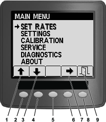
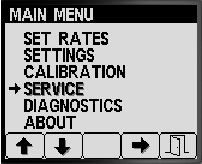
  1. To access the Service screen press button 2 on the Main Menu screen to navigate to the SERVICE option (Figure 79); refer to Accessing the Main Menu Screen.

    g192026
  2. Press button 4 to select SERVICE sub-menu (Figure 79).

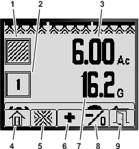
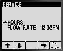
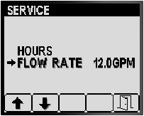
    This screen displays and allows you to display hours and flow rate information.

Viewing the Service Hours

  1. Press button 1 or 2 on the Service screen until you reach the HOURS option (Figure 80).

    g192029
  2. Press button 4 to select the Hours entry (Figure 80).

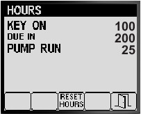
  3. Use the counter information (Figure 81) displayed on the screen to determine the following:

    g192028
    • The number of hours the key was in the ON position.

    • The number of until service is due.

    • The number hours the sprayer pump has run.

  4. To reset the hours for all counter information, press button 3 (Figure 81).

  5. Press button 5 to exit the HOURS screen, and return to the SERVICE screen (Figure 81).

Viewing the Flow Rate

While the sprayer pump is running, view the flow rate (Figure 82) measured by the flow meter in the following units of measure:

g192027
  • Gallons per minute

  • Liters per minute

Press button 5 to exit the SERVICE screen, and return to the MAIN MENU screen (Figure 82).

Diagnostics Screens

  1. To access the Diagnostics screen press buttons 1 or 2 on the Main Menu screen to navigate to the DIAGNOSTICS option (Figure 83); refer to Accessing the Main Menu Screen.

    g192025
  2. Press button 4 to select DIAGNOSTICS sub-menu (Figure 83).

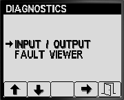
    This screen displays and allows you to display input, output, and fault information.

Viewing the Input/Output Report

  1. Press button 1 or 2 on the Diagnostics screen until you reach the INPUT/OUTPUT option (Figure 84).

    g192031
  2. Press button 3 to select the INPUT/OUTPUT entry (Figure 84).

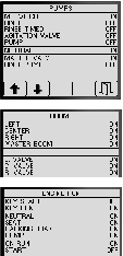
  3. Use buttons 1 or 2 to navigate and review the state information for the inputs and outputs of the sprayer system (Figure 85).

    g192033
  4. Press button 5 to exit the INPUT/OUTPUT screen, and return to the DIAGNOSTIC screen (Figure 84).

Viewing the Sprayer System Faults

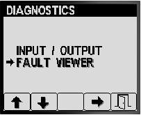
  1. Press button 1 or 2 on the Diagnostics screen until you reach the FAULT VIEWER option (Figure 86).

    g192030
  2. Press button 3 to select the FAULT VIEWER entry (Figure 86).

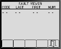
  3. Review the fault viewer for sprayer system generated faults (Figure 87).

    Note: If you see faults listed in the viewer, contact your Authorized Toro Service Dealer.

    g192032
  4. Press button 5 to exit the FAULT VIEWER screen, and return to the DIAGNOSTIC screen (Figure 87).

About Screens

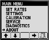
  1. To access the About screen press buttons 1 or 2 on the MAIN MENU screen to navigate to the ABOUT option (Figure 88).

    g192023
  2. Press button 4 to select About sub-menu (Figure 88).

    g192034
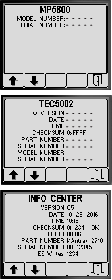
  3. Press buttons 1 or 2 to scroll the machine information screen, the TEC controller information screen, or the InfoCenter information screen (Figure 89).

  4. Press button 5 to exit the ABOUT screen, and return to the DIAGNOSTIC screen (Figure 87).