


Maintenance
Note: Determine the left and right sides of the machine from the normal operating position.
Maintenance Safety
-
Park machine on level ground, disengage drives, set parking brake, stop engine, and remove key. Wait for all moving parts to stop before leaving the operator’s position. Allow the machine to cool before servicing, adjusting, fueling, cleaning, or storing.
Warning
The engine can become very hot. Touching a hot engine can cause severe burns.
Allow the engine to cool completely before service or making repairs around the engine area.
-
If you leave the key in the switch, someone could accidently start the engine and seriously injure you or other bystanders. Remove the key from the switch before you perform any maintenance.
-
Never allow untrained personnel to service machine.
-
Keep all guards, shields, switches, and all safety devices in place and in proper working condition. Frequently check for worn or deteriorating components and replace them with genuine Exmark parts when necessary.
Warning
Removal or modification of original equipment, parts and/or accessories may alter the warranty, controllability, and safety of the machine. Unauthorized modifications to the original equipment or failure to use original Exmark parts could lead to serious injury or death. Unauthorized changes to the machine, engine, fuel or venting system, may violate applicable safety standards such as: ANSI, OSHA and NFPA and/or government regulations such as EPA and CARB.
-
Keep your hands and feet away from moving parts or hot surfaces. If possible, Do Not make adjustments with the engine running.
Warning
Contact with moving parts or hot surfaces may cause personal injury.
Keep your fingers, hands, and clothing clear of rotating components and hot surfaces.
-
Keep all parts in good working condition and all hardware tightened.
Recommended Maintenance Schedule(s)
| Maintenance Service Interval | Maintenance Procedure |
|---|---|
| Before each use or daily |
|
| Yearly |
|
Periodic Maintenance
Inspect StandOn
| Maintenance Service Interval | Maintenance Procedure |
|---|---|
| Before each use or daily |
|
-
Stop engine, wait for all moving parts to stop, and remove key. Engage parking brake.
-
Inspect for loose hardware. Tighten any loose hardware.
-
Inspect for wear or damage daily. Replace or repair worn parts as needed before operating.
Check StandOn for Buildup
| Maintenance Service Interval | Maintenance Procedure |
|---|---|
| Before each use or daily |
|
Check for dirt/mud buildup between tire and fender. Remove buildup before operating.
Note: You can wash the StandOn with mild detergent and water. Do not pressure wash the machine.
Lubricate Grease Fittings
| Maintenance Service Interval | Maintenance Procedure |
|---|---|
| Yearly |
|
Note: See chart for service intervals.
-
Stop engine, wait for all moving parts to stop, and remove key. Engage parking brake.
-
Lubricate fittings with NLGI grade #2 multi-purpose gun grease.
Refer to the following chart for fitting locations and lubrication schedule.
Lubrication Chart Fitting Locations Initial Pumps Number of Places Service Interval 1. Caster Wheel Hub 0 1 Yearly
Lubricate Caster Wheel Hubs
| Maintenance Service Interval | Maintenance Procedure |
|---|---|
| Yearly |
|
-
Stop engine, wait for all moving parts to stop, and remove key. Engage parking brake.
-
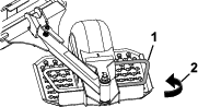
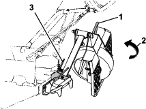
Remove the caster wheel from the sulky frame.
-
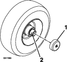
Remove seal guards from the wheel hub.
-
Remove one of the spacer nuts from the axle assembly in the caster wheel. Note that thread locking adhesive has been applied to lock the spacer nuts to the axle. Remove the axle (with the other spacer nut still assembled to it) from the wheel assembly.
-
Pry out seals, and inspect bearings for wear or damage and replace if necessary.
-
Pack the bearings with a NLGI grade #1 multi-purpose grease.
-
Insert one bearing, one new seal into the wheel.
Note: Seals (Exmark PN 103-0063) must be replaced.
-
If the axle assembly has had both spacer nuts removed (or broken loose), apply a thread locking adhesive to one spacer nut and thread onto the axle with the wrench flats facing outward. Do Not thread spacer nut all of the way onto the end of the axle. Leave approximately 1/8 inch (3 mm) from the outer surface of the spacer nut to the end of the axle inside the nut.
-
Insert the assembled nut and axle into the wheel on the side of the wheel with the new seal and bearing.
-
With the open end of the wheel facing up, fill the area inside the wheel around the axle full of NLGI grade #1 multi-purpose grease.
-
Insert the second bearing and new seal into the wheel.
-
Apply a thread locking adhesive to the second spacer nut and thread onto the axle with the wrench flats facing outward.
-
Torque the nut to 75-80 in-lb (8-9 N-m), loosen, then re-torque to 20-25 in-lb (2-3 N-m). Make sure axle does not extend beyond either nut.
-
Reinstall the seal guards over the wheel hub and insert wheel into the sulky frame. Reinstall caster pin and bow tie cotter pin.
Important: To prevent seal and bearing damage, check the bearing adjustment often. Spin the caster tire. The tire should not spin freely (more than 1 or 2 revolutions) or have any side play. If the wheel spins freely, adjust torque on spacer nut until there is a slight amount of drag. Reapply thread locking adhesive.
Adjustments
Tire Adjustment
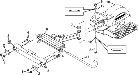
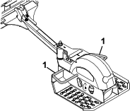
To obtain additional ground clearance, the platform wheel can be repositioned (see Figure 10).
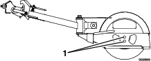
Note: To achieve more ground clearance for higher cutting heights, raise the platform by using the lower wheel adjustment hole.