Installation
Purchasing the Debris Shields
Parts needed for this procedure:
| Left debris shield (sold separately—Toro Part No. 134-0286-03) | 1 |
| Right debris shield (sold separately—Toro Part No. 134-0287-03) | 1 |
Purchase the left and right debris shields from your authorized Toro distributor.
Preparing the Machine
-
Park the machine on a level surface.
-
Engage the parking brake.
-
Lower the cutting units.
-
Shut off the engine and remove the key.
-
Wait for all moving parts to stop.
-
Unlatch and raise the operator’s platform.
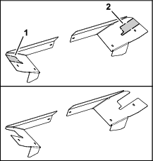
Removing the Debris Shield
Removing the Shields
-
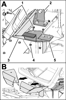
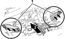
Remove the 3 flange-head capscrews (6 x 25 mm) and 3 flange locknuts (6 mm) that secure the debris shield to the platform support and the platform pivot bracket, and remove the debris shield from the machine (Figure 2).
-
Repeat step 1 at the other side of the machine.
Discarding Removed Parts
Discard the flange-head capscrews, flange locknuts, and debris shield that you removed in Removing the Shields.
Retaining and Discarding Removed Parts
-
Retain the debris shield that you removed in Removing the Debris Shield.
-
Discard the flange-head capscrews and flange locknuts that you removed in Removing the Debris Shield.
Drilling the Platform Supports
Checking the Platform Supports
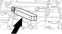
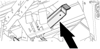
Look at the vertical flange (Figure 3) of the left and right platform supports. If the vertical flanges have holes, skip to Assembling the Mirror Arms.
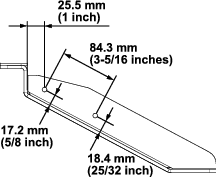
Drilling the Left Platform Support
-
Measure the platform bracket 25.5 mm (1 inch) as shown in Figure 4, and mark the bracket.
-
Measure the platform bracket 17.2 mm (5/8 inch) as shown in Figure 4, and mark the bracket.
-
Measure the platform bracket 84.3 mm (3-5/16 inch) as shown in Figure 4, and mark the bracket.
-
Measure the platform bracket 18.4 mm (25/32 inch) as shown in Figure 4, and mark the bracket.
-
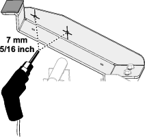
Centerpunch the platform bracket at the intersecting marks.
-
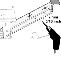
Drill a 7 mm (1/4 inch hole) at each of the centerpunch marks (Figure 5).
-
Remove any burrs from the holes.
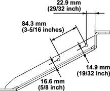
Drilling the Right Platform Support
-
Measure the platform bracket 22.9 mm (29/32 inch) as shown in Figure 6, and mark the bracket.
-
Measure the platform bracket 14.9 mm (9/16 inch) as shown in Figure 6, and mark the bracket.
-
Measure the platform bracket 84.3 mm (3-5/16 inch) as shown in Figure 6, and mark the bracket.
-
Measure the platform bracket 16.1 mm (5/8 inch) as shown in Figure 6, and mark the bracket.
-
Centerpunch the platform bracket at the intersecting marks.
-
Drill a 7 mm (1/4 inch hole) at each of the centerpunch marks (Figure 7).
-
Remove any burrs from the holes.
Assembling the Mirror Arms
Parts needed for this procedure:
| Left mirror bracket | 1 |
| Right mirror bracket | 1 |
| Mirror arm | 2 |
| Countersunk screw (6 x 16 mm) | 2 |
| Flange-head screw (6 x 20 mm) | 2 |
| Washer | 2 |
-
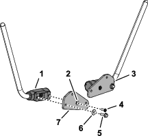
Align the holes in the left mirror bracket with the holes in a mirror-arm mount as shown in Figure 8.
Note: The difference between the left mirror bracket and the right mirror bracket is the location of the countersink. Align the countersink of the mirror bracket away from the mirror-arm mount.
-
Secure the mirror bracket to the mirror-arm mount (Figure 8) with a flange-head screw (6 x 20 mm) and washer, and a countersunk screw (6 x 16 mm).Figure 8).
-
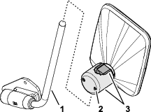
Loosen the 2 socket head screws that secure the halves of the mirror clamp (Figure 9).
-
Assemble the mirror arm into the mirror clamp and tighten the 2 socket head screws (Figure 9).
-
Align the holes in the right mirror bracket with the holes in a mirror-arm mount (Figure 8).
Note: Align the countersink of the mirror bracket away from the mirror-arm mount.
-
Repeat step 2 through 4 for the mirror bracket, mirror-arm, and mirror.
Assembling the Mirrors to the Machine
Parts needed for this procedure:
| Flange-head screw (6 x 25 mm) | 4 |
| Flange locknut (6 mm) | 4 |
Note: Determine the left and right sides of the machine from the normal operating position.
-
Align the holes of the left mirror bracket to the holes in the vertical flange of the left platform support (Figure 10).
-
Secure the mirror bracket to the platform support (Figure 10) with 2 flange-head screws (6 x 25 mm) and 2 flange locknut (6 mm).
-
Align the holes of the right mirror bracket to the holes in the vertical flange of the right platform support (Figure 10).
-
Secure the mirror bracket to the platform support (Figure 10) with 2 flange-head screws (6 x 25 mm) and 2 flange locknut (6 mm).
Preparing the Debris Shields
Installing the Debris Shield
Parts needed for this procedure:
| Flange-head screw (6 x 20 mm) | 6 |
| Flange locknut (6 mm) | 6 |
-
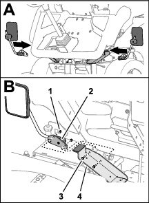
Align the holes in the left debris shield with the holes in the left platform support and the hole in the platform-pivot bracket (Figure 12).
-
Secure the debris shield to the platform support and pivot bracket (Figure 12) with 3 flange-head screws (6 x 20 mm) and 3 flange locknuts (6 mm).
-
Align the holes in the right debris shield with the holes in the right platform support and the hole in the platform-pivot bracket (Figure 12).
-
Secure the debris shield to the platform support and pivot bracket with 3 flange-head screws (6 x 20 mm) and 3 flange locknuts (6 mm).