| Maintenance Service Interval | Maintenance Procedure |
|---|---|
| Before each use or daily |
|
Introduction
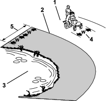
This aerator is intended to be used by trained operators in residential and commercial applications. It is primarily designed for aerating areas of well-maintained lawns on residential grounds, parks, sports fields, and on commercial grounds.
Read this information carefully to learn how to operate and maintain your product properly and to avoid injury and product damage. You are responsible for operating the product properly and safely.
Visit www.Toro.com for product safety and operation training materials, accessory information, help finding a dealer, or to register your product.
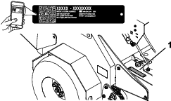
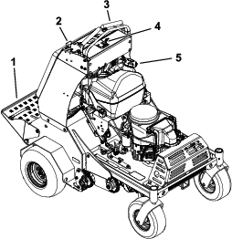
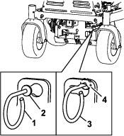
Whenever you need service, genuine Toro parts, or additional information, contact an Authorized Service Dealer or Toro Customer Service and have the model and serial numbers of your product ready. Figure 1 identifies the location of the model and serial numbers on the product. Write the numbers in the space provided.
Important: With your mobile device, you can scan the QR code on the serial number decal (if equipped) to access warranty, parts, and other product information.
This manual identifies potential hazards and has safety messages identified by the safety-alert symbol (Figure 2), which signals a hazard that may cause serious injury or death if you do not follow the recommended precautions.

This manual uses 2 words to highlight information. Important calls attention to special mechanical information and Note emphasizes general information worthy of special attention.
It is a violation of California Public Resource Code Section 4442 or 4443 to use or operate the engine on any forest-covered, brush-covered, or grass-covered land unless the engine is equipped with a spark arrester, as defined in Section 4442, maintained in effective working order or the engine is constructed, equipped, and maintained for the prevention of fire.
The enclosed engine owner's manual is supplied for information regarding the US Environmental Protection Agency (EPA) and the California Emission Control Regulation of emission systems, maintenance, and warranty. Replacements may be ordered through the engine manufacturer.
Warning
CALIFORNIA
Proposition 65 Warning
The engine exhaust from this product contains chemicals known to the State of California to cause cancer, birth defects, or other reproductive harm.
Battery posts, terminals, and related accessories contain lead and lead compounds, chemicals known to the State of California to cause cancer and reproductive harm. Wash hands after handling.
Use of this product may cause exposure to chemicals known to the State of California to cause cancer, birth defects, or other reproductive harm.
Safety
Safety Alert Symbol
This Safety Alert Symbol (Figure 3) is used both in this manual and on the machine to identify important safety messages which must be followed to avoid accidents.
This symbol means: ATTENTION! BECOME ALERT! YOUR SAFETY IS INVOLVED!
The safety alert symbol appears above information which alerts you to unsafe actions or situations and will be followed by the word DANGER, WARNING, or CAUTION.
DANGER: Indicates an imminently hazardous situation which, if not avoided, Will result in death or serious injury.
WARNING: Indicates a potentially hazardous situation which, if not avoided, Could result in death or serious injury.
CAUTION: Indicates a potentially hazardous situation which, if not avoided, May result in minor or moderate injury.
This manual uses two other words to highlight information. Important calls attention to special mechanical information and Note emphasizes general information worthy of special attention.
General Safety
This machine is capable of amputating hands and feet and of throwing objects. Toro designs and tests this machine to offer reasonably safe service; however, failure to comply with safety instructions may result in injury or death.
-
Read, understand, and follow all instructions and warnings in the Operator’s Manual and other training material, on the machine, engine, and attachments. All operators and mechanics should be trained. If the operator(s) or mechanic(s) can not read this manual, it is the owner’s responsibility to explain this material to them; other languages may be available on our website.
-
Only allow trained, responsible, and physically capable operators that are familiar with the safe operation, operator controls, and safety signs and instructions to operate the machine. Never let children or untrained people operate or service the equipment. Local regulations may restrict the age of the operator.
-
Do Not operate the machine near drop-offs, ditches, embankments, water, or other hazards.
-
Do Not put your hands or feet near moving components of the machine.
-
Never operate the machine with damaged guards, shields, or covers. Always have safety shields, guards, switches and other devices in place and in proper working condition.
-
Stop the machine, shut off the engine, and remove the key before servicing, fueling, or unclogging the machine.
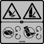
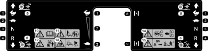
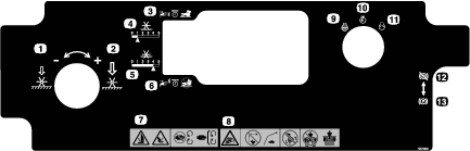
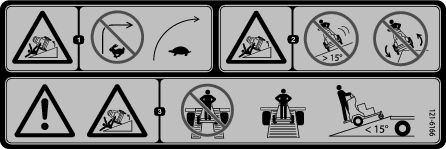
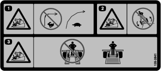
Safety and Instructional Decals
 |
Safety decals and instructions are easily visible to the operator and are located near any area of potential danger. Replace any decal that is damaged or missing. |


Setup
Checking Tire Air Pressure
Check the air pressure in the drive tires, and adjust the pressure as needed; refer to Checking the Air Pressure in the Tires.
Note: You do not adjust air pressure for the semi-pneumatic caster tires.
Servicing the Battery
Note: The machine is shipped with a filled, lead-acid battery.
-
Move the key switch to the OFF position and remove the key.
-
Measure the voltage of the battery with a voltmeter.
-
Use the table below to locate the charge state or the battery, and if needed, the battery-charger setting and charging interval recommended to charge the battery to 12.6 V or greater; refer to the battery charge table below.
Important: Make sure that the negative battery cable is disconnected and the battery charger used for charging the battery has an output of 16 V and 7 A or less to avoid damaging the battery (see chart for recommended charger settings).
Battery Charge Table
Voltage Reading Percent Charge Maximum Charger Settings Charging Interval 12.6 or greater 100% 16 V/ No charging required 7 A 12.4 to 12.6 75 to 100% 16 V/ 30 minutes 7 A 12.2 to 12.4 50 to 75% 16 V/ 1 hour 7 A 12.0 to 12.2 25 to 50% 14.4 V/ 2 hours 4 A 11.7 to 12.0 0 to 25% 14.4 V/ 3 hours 4 A 11.7 or less 0% 14.4 V/ 6 hours or more 2 A -
If the positive cable is also disconnected, connect the positive (red) cable to the positive battery terminal and slip the terminal cover over the positive terminal.
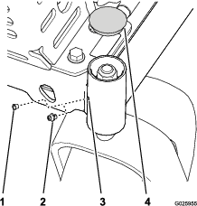
-
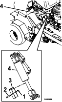
Remove the screw, washer, and ground cable from the engine. Connect the negative battery cable as shown in Figure 4.
Note: If time does not permit charging the battery or if charging equipment is not available, connect the negative battery cables and run the vehicle continuously for 20 to 30 minutes to charge the battery.
Servicing the Engine Oil
The engine is shipped with oil; check the engine-oil level and, if necessary, add oil to the appropriate level. Refer to Checking the Engine-Oil Level for instructions and the oil specification.
Servicing the Transmission Fluid
The machine is shipped with transmission fluid; check the transmission-fluid level and, if necessary, add fluid to the appropriate level. Refer to Checking the Transmission Fluid Level for instructions and the oil specification.
Servicing the Auxiliary Hydraulic Fluid
The machine is shipped with hydraulic fluid; check the hydraulic-fluid level and, if necessary, add fluid to the appropriate level. Refer to Checking the Auxiliary Hydraulic-Fluid Level for instructions and the oil specification.
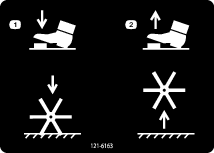
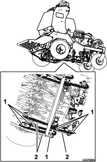
Removing the Cylinder Stop
Note: Raise the tines before removing the cylinder stop. Running the engine charges the hydraulic system and raises the tines.
-
Add a small amount of fuel to the fuel tank; refer to Fueling the Machine.
-
Open the fuel-shutoff valve by aligning the lever for the fuel-shutoff valve with the fuel line; refer to Fuel-Shutoff Valve.
-
Move the motion-control levers to the neutral position and engage the parking brake; refer to Motion-Control Levers.
-
Place the throttle midway between the SLOW and FAST positions; refer to Throttle Lever.
-
Push forward the choke lever to set the choke to the ON position; refer to Choke Lever.
-
Turn the key switch to the START position; refer to Key Switch .
Note: Release the switch as soon as the engine starts.
Important: Do not crank the engine continuously for more than 10 seconds at a time. If the engine does not start, allow a 60-second cooldown period between starting attempts. Failure to follow these guidelines can burn out the starter motor.
-
Gradually move the lever for the choke lever to the OFF position as the engine warms up.
Note: Allow the engine to run an additional 30 seconds
-
Turn the key switch to the OFF position to shut off the engine.
-
Remove the key and pull the wires off the spark plugs.
Note: Push the wires aside so they do not accidentally contact the spark plugs.
-
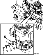
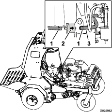
Remove and retain the hairpin, clevis pin, and cylinder stop as shown in Figure 5.
-
Connect the spark-plug wires.
Product Overview
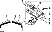
Motion-Control Levers
The motion-control levers are located on each side of the top console and control the forward and reverse motion of the machine.
Move the levers forward or backward to control the drive wheel on the same side forward or reverse respectively. The wheel speed is proportional to the amount you move the lever.
Important: The tines rotate when the motion-control levers are moved out of the NEUTRAL position.
Throttle Lever
The throttle lever (Figure 8) is located on the control console (red lever).
Use the throttle lever to control engine speed. Move the throttle lever forward to increase engine speed; moving the throttle lever rearward to decrease the engine speed.
Note: Move the throttle lever forward into the detent for full throttle.
Choke Lever
The choke lever (Figure 8) is located on the control console (black lever).
Use the choke lever is used to aid in starting a cold engine. Move the choke lever forward to set the choke to the ON position; move the choke lever to the rearward to reduce the choke.
Note: Pull the choke lever back into the detent to set the choke to the OFF position.
Note: Do not run a warm engine with the choke in the ON position.
Parking-Brake Handle
The parking-brake handle is located on the control console, to the right of the key switch (Figure 8).
Note: The brake handle engages a parking brake in each of the transmissions.
-
To engage the parking brake, pull the handle out and slide it rearward.
-
To release the parking brake, push the handle forward into the detent.
When parking on a steep slope, chock or block the wheels in addition to engaging the parking brake. Tie down the machine and engage the parking brake when transporting the machine.
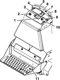
Hour Meter/Tine Engagement Display
Located to the left of the ignition switch on the control console.
-
The hour meter monitors and displays the engine hours.
Hours are displayed when the key is off or when the machine is running. Hours are not displayed when the machine is aerating.
Note: The LCD indicator appears in the park brake setting when it meets the “safe to start” mode (parking brake engaged).
-
The tine-engagement display monitors and displays the electronic tine-depth setting.
There are 2 ways to activate the display:
-
Tap the multi-function switch either up or down to display the tine-engagement meter.
-
Step on the tine ground-engagement foot switch.
A higher number on the status bar increases the length of the aeration plug and a lower number decreases it.
Note: If the plug length is not desired length, the machine may need to be adjusted to accommodate for the weight of the operator; refer to Operator Weight-Adjustment Control for more information.
LED Status Lights
Located on the right side of the hour meter/tine-engagement display.
The LED is multi-colored to indicate the system status and is located on the right side of the panel.
-
Solid green—indicates normal operating activity.
-
Blinking red—indicates a fault is active.
-
Solid red—indicates maintenance is required.
Tines Ground-Engagement Foot Switch
The switch is located on the operator platform (Figure 8).
To lower the tines into the ground, stand on the tine ground-engagement switch. The LED illuminates in the hour meter/tine engagement display when the tine engagement is activated. To raise the tines, remove your foot from the switch.
This switch can be disabled with the multi-function switch.
-
Tap and hold the bottom of the switch to override and disable the foot switch. The LED illuminates in the hour meter/tine engagement display. Use this feature when transporting the machine.
-
To unlock, tap and hold the top of the multi-function switch until the LED light disappears.
Note: The disable feature is engaged each time you shut off the engine.
Key Switch
Operator Weight-Adjustment Control
Located on the left side of the control console (Figure 8).
This feature takes into account the weight of the operator so that the correct aerating pressure and plug length is achieved and to maximize lateral machine stability. Rotating the control counterclockwise decreases the pressure and rotating it clockwise increases it; Adjusting the Operator Weight Control Setting.
Note: Each operator must adjust the system pressure so that the drive tires lightly touch the ground.
Important: Keep the drive tires on the ground at all times to maximize lateral machine stability.
Multi-Function Switch
Located to the left of the hour meter/tine-engagement display.
This switch allows you to do the following:
-
Increase/decrease the depth of an aeration plug.
-
Lock or unlock the tine-depth setting.
-
Lock or unlock the tine ground-engagement foot switch.
Fuel-Shutoff Valve
The fuel-shutoff valve is located behind the engine and under the fuel tank (Figure 12).
Use the fuel-shutoff valve to shut off the fuel when the machine will not be used for a few days, when transporting the machine to and from the jobsite, or when the machine is parked inside a building.
-
To open for fuel-shutoff valve, rotate the handle of the fuel-shutoff valve until it is aligned with the fuel line.
-
To close the fuel-shutoff valve, rotate the handle 90° to the fuel line.
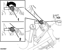
Drive-Wheel Release Valves
Warning
Your hands may become entangled in the rotating drive components below the engine deck, which could result in serious injury or death.
Shut off the engine, remove the key, and allow all moving parts to stop before accessing the drive-wheel release valves.
Warning
The engine and hydraulic components can become very hot. Touching a hot engine or hydraulic components can cause severe burns.
Allow the engine and hydraulic components to cool completely before accessing the drive-wheel release valves.
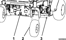
Located on the left and right sides underneath the front of the machine.
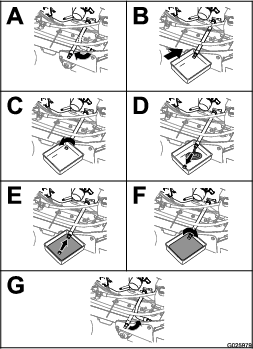
During normal operating conditions, the washer on the lever is positioned outside the slots. If the machine has to be pushed by hand, the valves must be in the released position (Figure 13).
To release the drive wheels, move the lever to the larger opening of the slot, push it in until the washer is inside the frame, then move the lever back to the narrow portion of the slot. Repeat this on each side of the machine.
Disengage the parking brake. The machine is now able to be pushed by hand.
Do not tow machine.
To reset the drive system back to the operating position:
Move the lever to the larger opening of the slot, pull outward until the washer is outside the frame, then move the lever back to the narrow portion of the slot. Repeat this on each side of the machine.
| Height | 132 cm (52 inches) |
| Length | 163 cm (64 inches) |
| Width | 121 cm (48 inches) |
| Aeration width | 76 cm (30 inches) |
| Coring range | 5.1 to 12.7 cm (2 to 5 inches) |
| Weight | 460 kg (1,015 lb) |
A selection of Toro approved attachments and accessories is available for use with the machine to enhance and expand its capabilities. Contact your Authorized Service Dealer or Distributor.
To best protect your investment and maintain optimal performance of your Toro equipment, count on Toro genuine parts. When it comes to reliability, Toro delivers replacement parts designed to the exact engineering specification of our equipment. For peace of mind, insist on Toro genuine parts.
Operation
Note: Determine the left and right sides of the machine from the normal operating position.
Before Operation
Before Operation Safety
-
Evaluate the terrain to determine what accessories and attachments are needed to properly and safely perform the job. Only use accessories and attachments approved by Toro.
-
Inspect the area where the equipment is to be used and remove all rocks, toys, sticks, wires, bones, and other foreign objects. These can be thrown or interfere with the operation of the machine and may cause personal injury to the operator or bystanders.
-
Mark and avoid hidden objects such as sprinkler heads, underground wires/cables, invisible fences, etc. to prevent damage to these systems when aerating.
-
Wear appropriate personal protective equipment such as safety glasses, substantial slip-resistant footwear, and hearing protection. Tie back long hair and avoid loose clothing and loose jewelry which may get tangled in moving parts.
Caution
This machine produces sound levels in excess of 85 dBA at the operator’s ear and can cause hearing loss through extended periods of exposure.
Wear hearing protection when operating this machine.
-
Check that the operator presence controls, safety switches, and shields are attached and functioning properly. Do Not operate unless they are functioning properly.
-
Do Not operate the machine when people, especially children, or pets are in the area. Stop the machine and attachment(s) if anyone enters the area.
-
Do Not operate the machine with damaged guards, shields, or covers. Always have safety shields, guards, switches and other devices in place and in proper working condition. Frequently check for worn or deteriorating components and replace them with the manufacturer’s recommended parts when necessary.
Fuel Safety
Use extreme care when handling fuel.
Danger
In certain conditions gasoline is extremely flammable and vapors are explosive.
A fire or explosion from gasoline can burn you, others, and cause property damage.
-
Fill the fuel tank outdoors on level ground, in an open area, when the engine is cold. Wipe up any gasoline that spills.
-
Never refill the fuel tank or drain the machine indoors or inside an enclosed trailer.
-
Do Not fill the fuel tank completely full. Fill the fuel tank to the bottom of the filler neck. The empty space in the tank allows gasoline to expand. Overfilling may result in fuel leakage or damage to the engine or emission system.
-
Never smoke when handling gasoline, and stay away from an open flame or where gasoline fumes may be ignited by spark.
-
Store gasoline in an approved container and keep it out of the reach of children.
-
Add fuel before starting the engine. Never remove the cap of the fuel tank or add fuel when engine is running or when the engine is hot.
-
If fuel is spilled, Do Not attempt to start the engine. Move away from the area of the spill and avoid creating any source of ignition until fuel vapors have dissipated.
-
Do Not operate without entire exhaust system in place and in proper working condition.
Danger
In certain conditions during fueling, static electricity can be released causing a spark which can ignite gasoline vapors. A fire or explosion from gasoline can burn you and others and cause property damage.
-
Always place gasoline containers on the ground away from your vehicle before filling.
-
Do Not fill gasoline containers inside a vehicle or on a truck or trailer bed because interior carpets or plastic truck bed liners may insulate the container and slow the loss of any static charge.
-
When practical, remove gas-powered equipment from the truck or trailer and refuel the equipment with its wheels on the ground.
-
If this is not possible, then refuel such equipment on a truck or trailer from a portable container, rather than from a gasoline dispenser nozzle.
-
If a gasoline dispenser nozzle must be used, keep the nozzle in contact with the rim of the fuel tank or container opening at all times until fueling is complete. Do Not use a nozzle lock open device.
Warning
Gasoline is harmful or fatal if swallowed. Long-term exposure to vapors has caused cancer in laboratory animals. Failure to use caution may cause serious injury or illness.
-
Avoid prolonged breathing of vapors.
-
Keep face away from nozzle and gas tank/container opening.
-
Keep away from eyes and skin.
-
Never siphon by mouth.
To help prevent fires:
-
Keep engine and engine area free from accumulation of grass, leaves, excessive grease or oil, and other debris which can accumulate in these areas.
-
Clean up oil and fuel spills and remove fuel soaked debris.
-
Allow the machine to cool before storing the machine in any enclosure. Do Not store near flame or any enclosed area where open pilot lights or heat appliances are present.
Adding Fuel
Danger
In certain conditions, fuel is extremely flammable and highly explosive. A fire or explosion from fuel can burn you and others and can damage property.
-
Fill the fuel tank outdoors, in an open area, and when the engine is cold. Wipe up any fuel that spills.
-
Do not fill the fuel tank completely full. Add fuel to the fuel tank until the level is 6 to 13 mm (1/4 to 1/2 inch) below the bottom of the filler neck. This empty space in the tank allows the fuel to expand.
-
Never smoke when handling fuel, and stay away from an open flame or where a spark may ignite the fuel fumes.
-
Store fuel in an approved fuel container and keep it out of the reach of children.
-
Never buy more than a 30-day supply of fuel.
Danger
In certain conditions during fueling, static electricity can be released, causing a spark, which can ignite the fuel vapors. A fire or explosion from fuel can burn you and others and can damage property.
-
Always place fuel containers on the ground away from your vehicle before filling.
-
Do not fill fuel containers inside a vehicle or on a truck or trailer bed because interior carpets or plastic truck bed liners may insulate the container and slow the loss of any static charge.
-
When practical, remove fuel-powered equipment from the truck or trailer and refuel the equipment with its wheels on the ground.
-
If this is not possible, then refuel such equipment on a truck or trailer from a portable container rather than from a fuel-dispenser nozzle.
-
If you must use a fuel-dispenser nozzle, keep the nozzle in contact with the rim of the fuel tank or container opening at all times until fueling is complete.
Warning
Fuel is harmful or fatal if swallowed. Long-term exposure to vapors can cause serious injury and illness.
-
Avoid prolonged breathing of vapors.
-
Keep your face away from the nozzle and fuel tank or conditioner bottle opening.
-
Avoid contact with skin; wash off spills with soap and water.
Fuel Specification
| Petroleum fuel | Use unleaded gasoline with an octane rating of 87 or higher ((R+M)/2 rating method). |
| Ethanol blended fuel | Use an unleaded-gasoline blend with up to 10% ethanol (gasohol) or 15% MTBE (methyl tertiary butyl ether) by volume is acceptable. Ethanol and MTBE are not the same. |
| Gasoline with 15% ethanol (E15) by volume is not approved for use. Never use gasoline that contains more than 10% ethanol by volume, such as E15 (contains 15% ethanol), E20 (contains 20% ethanol), or E85 (contains up to 85% ethanol). Using unapproved gasoline may cause performance problems and/or engine damage which may not be covered under warranty. |
Important: For best results, use only clean, fresh fuel (less than 30 days old).
-
Do not use gasoline containing methanol.
-
Do not store fuel either in the fuel tank or fuel containers over the winter unless you use a fuel stabilizer.
-
Do not add oil to gasoline.
Using Stabilizer/Conditioner
Use fuel stabilizer/conditioner in the machine at all times to keep the fuel fresh longer when used as directed by the fuel-stabilizer manufacturer.
Important: Do not use fuel additives containing methanol or ethanol.
Add the amount of fuel stabilizer/conditioner to fresh fuel as directed by the fuel-stabilizer manufacturer.
Fueling the Machine
Fuel-tank capacity: 18.9 L (5 US Gallons)
-
Clean around the fuel-tank cap.
-
Remove the cap from the tank.
-
Fill the fuel tank with fuel to within 6 to 13 mm (1/4 to 1/2 inch) from the top of the tank. Do not fill into the filler neck.
Important: Do not fill the tank more than 6 mm (1/4 inch) from the top of the tank because the fuel must have room to expand.
-
Install the fuel-tank cap and wipe up any spilled fuel.
Performing Daily Maintenance
Before starting the machine each day, perform the Each Use/Daily procedures listed in .
Checking the Safety-Interlock System
Caution
If the safety-interlock switches are disconnected or damaged, the machine could operate unexpectedly, causing personal injury.
-
Do not tamper with the interlock switches.
-
Check the operation of the interlock switches daily and replace any damaged switches before operating the machine.
Understanding the Safety-Interlock System
The safety-interlock system is designed to prevent the engine from starting unless the motion-control levers are in the neutral position.
Checking the Safety-Interlock System
-
Disconnect the spark-plug wires.
-
While on level ground, block the wheels of the machine to prevent unintended movement.
-
Disengage the parking brake.
-
With the motion-control levers in the neutral position turn the key to the START position—the starter must not crank.
Note: If the machine does not pass this test, do not operate the machine. Contact your Authorized Service Dealer.
Important: It is essential that the operator safety mechanisms are connected and in proper operating condition prior to use.
Checking for Loose Hardware
| Maintenance Service Interval | Maintenance Procedure |
|---|---|
| Before each use or daily |
|
-
Shut off the engine, engage the parking brake, remove the key, and wait for all moving parts to stop.
-
Visually inspect machine for any loose hardware or any other possible problem.
Note: Tighten all loose hardware or repair the problem before operating the machine.
During Operation
During Operation Safety
General Safety
The operator must use their full attention when operating the machine. Do Not engage in any activity that causes distractions; otherwise, injury or property damage may occur.
Warning
Operating engine parts, especially the muffler, become extremely hot. Severe burns can occur on contact and debris, such as leaves, grass, brush, etc. can catch fire.
-
Allow engine parts, especially the muffler, to cool before touching.
-
Remove accumulated debris from muffler and engine area.
Warning
Engine exhaust contains carbon monoxide, which is an odorless deadly poison that can kill you.
Do Not run engine indoors or in a small confined area where dangerous carbon monoxide fumes can collect.
-
The owner/user can prevent and is responsible for accidents or injuries occurring to himself or herself, other people or property.
-
This machine was designed for one operator only. Do not carry passengers and keep all others away from machine during operation.
-
Do Not operate the machine under the influence of alcohol or drugs.
-
Operate only in daylight or good artificial light.
-
Lightning can cause severe injury or death. If lightning is seen or thunder is heard in the area, Do Not operate the machine; seek shelter.
-
Use extra care while operating with accessories or attachments. These can change the stability of the machine and cause a loss of control. Follow directions for counter weights if required.
-
Keep away from holes, ruts, bumps, rocks, and other hidden hazards. Use care when approaching blind corners, shrubs, trees, tall grass or other objects that may hide obstacles or obscure vision. Uneven terrain could overturn the machine or cause the operator to lose their balance or footing.
-
Be sure all drives are in neutral and parking brake is engaged before starting engine.
-
Start the engine carefully according to instructions with feet well away from the tines.
-
Never operate the machine with damaged guards, shields, or covers. Always have safety shields, guards, switches and other devices in place and in proper working condition.
-
Keep clear of the tines at all times.
-
Keep hands and feet away from moving parts. If possible, Do Not make adjustments with the engine running.
Warning
Hands, feet, hair, clothing, or accessories can become entangled in rotating parts. Contact with the rotating parts can cause traumatic amputation or severe lacerations.
-
Do Not operate the machine without guards, shields, and safety devices in place and working properly.
-
Keep hands, feet, hair, jewelry, or clothing away from rotating parts.
-
-
Be aware of the discharge path and direct discharge away from others. Avoid discharging material against a wall or obstruction as the material may ricochet back toward the operator. Raise the tines, slow down, and use caution when crossing surfaces other than grass and when transporting the machine to and from the work area.
-
Be alert, slow down and use caution when making turns. Look behind and to the side before changing directions. Do Not operate in reverse unless absolutely necessary.
-
Do Not change the engine governor setting or overspeed the engine.
-
Park the machine on level ground. Stop engine, wait for all moving parts to stop, and remove the spark plug wire(s).
-
Before checking, cleaning or working on the machine.
-
After striking a foreign object or abnormal vibration occurs (inspect the machine for damage and make repairs before restarting and operating the machine).
-
Before clearing blockages.
-
Whenever you leave the machine. Do Not leave a running machine unattended.
-
-
Stop engine, wait for all moving parts to stop:
-
Before refueling.
-
-
Tragic accidents can occur if the operator is not alert to the presence of children. Children are often attracted to the machine and the working activity. Never assume that children will remain where you last saw them.
-
Keep children out of the working area and under the watchful care of another responsible adult, not the operator.
-
Be alert and turn the machine off if children enter the area.
-
Before and while backing or changing direction, look behind, down, and side-to-side for small children.
-
Never allow children to operate the machine.
-
Do Not carry children, even with the blades shut off. Children could fall off and be seriously injured or interfere with the safe operation of the machine. Children that have been given rides in the past could suddenly appear in the working area for another ride and be run over or backed over by the machine.
-
Slope Safety
-
Slopes are a major factor related to loss of control and rollover accidents, which can result in severe injury or death. The operator is responsible for safe slope operation. Operating the machine on any slope requires extra caution. Before using the machine on a slope, the operator must:
-
Review and understand the slope instructions in the manual and on the machine.
-
Evaluate the site conditions of the day to determine if the slope is safe for machine operation. Use common sense and good judgment when performing this evaluation. Changes in the terrain, such as moisture, can quickly affect the operation of the machine on a slope.
-
-
Operate across slopes, never up and down. Avoid operation on excessively steep or wet slopes.
-
Identify hazards at the base of the slope. Do not operate the machine near drop offs, ditches, embankments, water or other hazards. The machine could suddenly roll over if a wheel goes over the edge or the edge collapses. Keep a safe distance (twice the width of the machine) between the machine and any hazard. Use a walk behind machine or a hand held tool to operate in these areas.
-
Avoid starting, stopping or turning the machine on slopes. Avoid making sudden changes in speed or direction; turn slowly and gradually.
-
Do not operate a machine under any conditions where traction, steering or stability is in question. Be aware that operating the machine on wet grass, across slopes or downhill may cause the machine to lose traction. Loss of traction to the drive wheels may result in sliding and a loss of braking and steering. The machine can slide even if the drive wheels are stopped.
-
Remove or mark obstacles such as ditches, holes, ruts, bumps, rocks or other hidden hazards. Tall grass can hide obstacles. Uneven terrain could overturn the machine.
-
Use extra care while operating with accessories or attachments. These can change the stability of the machine and cause a loss of control. Follow directions for counter weights.
-
If you lose control of the machine, step off and away from the direction of travel of the machine.
Using the Smart Controller/Electronic Depth Control
Hour Meter/Tine Engagement Display

The smart controller/electronic depth control monitors the overall electrical system and displays information in the hour meter/tine engagement display. The controller displays machine hours, interlock status, and maintenance reminders.
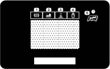
Screen Icons
The information screen uses the following icons:
 Aerating Hours |  Parking brake |
 Battery Voltage |  Engine Oil Maintenance |
 Hour Meter |  Transmission Oil Maintenance |
 Voltage Error |  Valve Solenoid Error |
 Valve Solenoid Connection Error |
Information Screens
The main information screens include:
-
The Startup Screens
-
The Default Screen (engine-on)
-
The Tine Engagement Display
-
Maintenance Reminders and Alerts
-
Alerts and Error Messages
Start-up Screens
When the key is switched from OFF to RUN position, the following screens display for 2 seconds:
Note: The LED status light changes from red to orange to green.
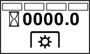
The first screen displays the firmware version.
The second screen displays the aeration hours.
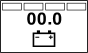
The third screen displays the electrical system voltage.
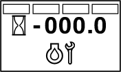
The fourth screen displays the number of hours until the engine oil maintenance is required.
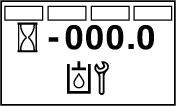
The final screen displayed is the number of hours until transmission oil maintenance is required.
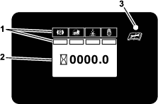
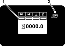
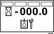
The Default Screen
After the start-up screens display, the default screen (Figure 20) appears.
The information screen displays icons and information relative to machine operation.
-
The safety interlock status indicator illuminates when the control meets the “safe to start” mode (park brake engaged).
-
The hour meter displays engine hours when the hour glass symbol is flashing.
-
The display turns off after 5 minutes after the ignition key is switched to the OFF position.
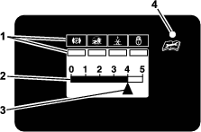
The Tine Engagement Display
Electronic Depth Control Screen
There are 2 ways to activate the tine engagement display:
-
Tap the multi-function switch either up or down to display the tine engagement meter.
-
Step on the tine ground engagement foot switch.
A higher number on the status bar (Figure 21) increases the length of the aeration plug and a lower number decreases it.
Note: If the plug length is not the desired length, you may need to adjust the machine to accommodate for your weight; refer to Adjusting the Operator Weight Control Setting.
LED Status Light
Maintenance Reminder Screens
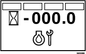
The hour meter displays the number of engine hours until either the engine oil or transmission oil maintenance is due. When maintenance is due, the smart controller/electronic depth control displays flashing icons for an engine oil maintenance alert or a transmission oil maintenance alert, and the LED status light displays a steady red light.
-
A maintenance alert occurs when the maintenance counter reaches zero.
-
If the service is not performed, the maintenance counter displays time as negative hours to indicate the number of hours past due for the service (up to -500 hours).
-
The hour meter switches between the default screen and the active alert screen.
-
If more than 1 alert is active, the display cycles between the alerts in the order that they occurred before cycling back to the default screen.
The maintenance alerts only display when the default screen has been active for 2 seconds; however, if the key is moved to the START position, the alerts occur immediately. When the machine is aerating, the alert screen does not display but the LED status light remains a steady red.
Service Engine Reminder
The engine-oil service reminder (Figure 22) counts down from the initial break-in service interval of 5 engine hours and then counts down from 100 hours for each service interval thereafter.
Service Transmission Reminder
The transmission oil maintenance reminder (Figure 23) counts down from the initial break-in service interval of 100 engine hours and then counts down from 250 hours for each service interval thereafter.
Operating the Machine
Using the Fuel-Shutoff Valve
Rotate the lever of the fuel-shutoff valve to align the lever with the fuel line.
Starting the Engine
-
Move the motion-control levers to the neutral position and engage the parking brake; refer to Motion-Control Levers and Parking-Brake Handle.
Note: To start the engine, the parking brake must be engaged. It is not necessary for the operator to be on the platform.
-
Place the throttle lever midway between the SLOW and FAST positions; refer to Throttle Lever.
-
If the engine is cold, push the choke lever forward to the ON position; refer to Choke Lever.
Note: If the engine is warm, pull the choke lever to the OFF position.
-
Rotate the key switch to the START position; refer to Key Switch .
Note: Release the switch as soon as the engine starts.
Important: Do not crank the engine continuously for more than 10 seconds at a time. If the engine does not start, allow a 60-second cooldown period between starting attempts. Failure to follow these guidelines can burn out the starter motor.
-
If the choke lever is in the ON position, gradually move the lever toward the OFF position as the engine warms up.
Lowering the Tines
Danger
The rotating tines under the engine deck are dangerous. Tine contact can cause serious injury or kill you.
Do not put your hands or feet under the machine when the engine is running.
-
Disengage the parking brake.
-
Move the throttle lever to the FAST position.
-
The lockout feature is engaged each time the engine is switched off. To unlock, tap and hold the top of the multi-function switch until the LED light disappears.
-
Tap the switch once to display the tine-engagement depth setting.
Note: Adjust if necessary.
-
Lower the tines by pressing the tine ground-engagement foot switch.
The LED indicator should illuminate under the tine down position on the hour meter.
-
Stand on the switch and move the motion-control levers forward to aerate.
Note: The foot-rocker bar, located behind the tine ground-engagement foot switch, can be adjusted for your comfort. To adjust, loosen the foot-rocker bar hardware, slide the bar forward or rearward, and tighten the hardware.
Locking/Unlocking the Tine Depth Setting
The settings can be locked to ensure that the tine depth is not inadvertently changed by the operator or left unlocked.
-
To activate the depth lock: turn the ignition key from the OFF position to the ON position 5 times (stop at the ON position). Use the multi-function switch to adjust the tine depth to the desired setting. Press and hold the multi-function switch down for 1 second to lock.
-
To deactivate the depth lock: turn the ignition key from the OFF position to the ON position 5 times (stop at the ON position). Press and hold the multi-function switch up for 1 second to unlock.
Switch the key to the OFF position or START position when you are finished.
Adjusting the Operator Weight Control Setting
-
With the tines raised, drive the machine to a hard, flat surface (such as concrete) and stop the aerator, but leave it running.
-
Set throttle to the FAST position and disengage the parking brake.
-
Use the multi-function switch to set the tine depth to 3.0; refer to Adjusting the Tine-Depth Setting.
-
Press and hold the tine ground-engagement foot switch to lower the tines.
-
If the machine raises and the ground tires are no longer touching, rotate the operator weight-adjustment control counterclockwise to lower the machine until the tires touch the ground.
-
If the tines are not touching the ground, rotate the operator weight-adjustment control clockwise until the tines lower and touch the ground (but do not raise the machine).
Important: Keep the drive tires on the ground at all times to maximize lateral machine stability and aeration quality.
-
-
Release the tine ground-engagement foot switch.
Adjusting the Tine-Depth Setting
Tap the multi-function switch up or down to set the aeration depth.
Tap the bottom of the multi-function switch to increase the tine depth to remove a longer plug.
Tap the top of the switch to decrease the tine depth to remove a shorter plug.
Note: You can make tine-depth adjustments with the multi-function switch only. The ideal plug depth is 6.4 to 7.6 cm (2-1/2 to 3 inches). Adjust the controls to adapt to the soil conditions.
Raising the Tines
To raise the tines, remove your foot from the tine-elevation switch (Figure 8).
Important: The tines rotate when the motion-control lever is moved out of the neutral position.
Shutting Off the Engine
-
Move the motion-control levers to the neutral position and bring the machine to a full stop; refer to Motion-Control Levers.
-
Lift your foot off the tine ground-engagement foot switch control to raise the tines; refer to Raising the Tines.
-
Place the throttle in the midway between the SLOW and FAST positions; refer to Throttle Lever.
-
Allow the engine to run for a minimum of 15 seconds, then turn the key switch to the OFF position to shut off the engine; refer to Key Switch .
-
Engage the parking brake; refer to Parking-Brake Handle.
-
Remove the key to prevent children or other unauthorized persons from starting the engine.
-
Close the fuel-shutoff valve when the machine will not be used for a few days, when transporting, or when the machine is parked inside a building; refer to Using the Fuel-Shutoff Valve.
Driving the Machine
Caution
Machine can spin very rapidly by positioning 1 lever too much ahead of the other. You may lose control of the machine, which may cause damage to the machine or injury.
-
Use caution when making turns.
-
Slow the machine down before making sharp turns.
Important: To drive the machine (forward or backward), disengage the brake lever before you can move the motion-control levers.
Driving Forward
-
Make sure that the motion-control levers are in the neutral position.
-
Disengage the parking brake.
-
To move forward in a straight line, move both levers forward with equal pressure.
Note: The machine moves faster the farther the motion-control levers are moved from the neutral position.
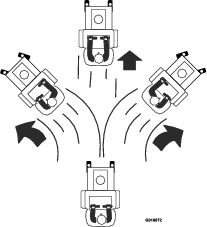
-
To turn left or right, pull the motion-control lever back toward neutral in the desired turn direction. The tines can be in the down position when making gradual turns.
-
To make zero-turns, lift your foot off the tine engagement foot switch control to raise the tines. The head raises in 1 second.
Important: Do not make a zero-turn when the tines are down, otherwise you may tear the turf.
-
To stop the machine, move both motion-control levers to the neutral position.
Driving in Reverse
-
Move the motion-control levers to the neutral position.
-
To move rearward in a straight line, slowly move both levers rearward with equal pressure.

-
To turn left or right, release pressure on the motion-control lever toward the desired turn direction.
-
To make zero-turns, lift your foot off the tine-elevation switch to raise the tines. The head raises in 1 second.
Important: Do not make a zero-turn when the tines are in the down position.
-
To stop the machine, position both motion-control levers in the neutral operate position.
Adjusting the Front Reference/Speed-Control Bar
Adjust the front reference/speed control bar for desired maximum forward speed.
-
Stop the machine and move the motion-control levers to the NEUTRAL position.
-
Loosen the nuts on each side of the control panel (Figure 28).
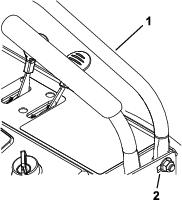
-
Move the bar forward to obtain the fastest speed.
Move the bar rearward to obtain the slowest speed.
-
On both sides, tighten the nuts and bolts.
Important: Ensure that the nuts and bolts are tight so that the front reference/speed-control bar does not move during operation.
After Operation
After Operation Safety
General Safety
-
Park machine on level ground, disengage drives, set parking brake, stop engine, remove key or disconnect spark plug wire. Wait for all movement to stop and allow the machine to cool before adjusting, cleaning, repairing, or storing. Never allow untrained personnel to service machine.
-
Clean the machine as stated in the Maintenance section. Keep engine and engine area free from accumulation of grass, leaves, excessive grease or oil, and other debris which can accumulate in these areas. These materials can become combustible and may result in a fire.
-
Frequently check for worn or deteriorating components that could create a hazard. Tighten loose hardware.
Transporting the Machine
Machine weight: 460 kg (1,015 lb)
Caution
This machine does not have proper turn signals, lights, reflective markings, or a slow moving vehicle emblem. Driving on a street or roadway without such equipment is dangerous and can lead to accidents, causing personal injury. Driving on a street or roadway without such equipment may also be a violation of state laws, and you may be subject to traffic tickets and/or fines.
Do not drive the machine on a public street or roadway.
Loading the Machine onto a Transport Vehicle
Warning
Loading the machine onto a trailer or truck increases the possibility of tip-over and could cause serious injury or death.
-
Use extreme caution when operating a machine on a ramp.
-
Use only a single, full-width ramp; do not use individual ramps for each side of the machine.
-
If you must use individual ramps, use enough ramps to create an unbroken ramp surface wider than the machine.
-
Do not exceed a 15-degree angle between ramp and ground, or between a ramp, a trailer, or a truck.
-
Avoid sudden acceleration while driving machine up a ramp to avoid tipping backward.
-
Avoid sudden deceleration while backing machine down a ramp to avoid tipping backward.
Important: Do not attempt to turn the machine while on the ramp; you may lose control and drive off the side.
-
Use extreme caution when loading units onto trailers or trucks.
-
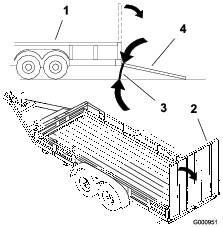
Use 1 full-width ramp that is wide enough to extend beyond the rear tires instead of individual ramps for each side of the machine (Figure 29). The platform, when down and locked into position, must extend back between the rear wheels and serves as a stop for tipping backward. Having a full-width ramp provides a surface for the platform to contact if the machine starts to tip backward. With the platform up, a full-width ramp provides a surface to walk on behind the machine.
-
The ramp should be long enough so that the angles do not exceed 15 degrees (Figure 29). A steeper angle may cause tine components to get caught, as the machine moves from ramp to trailer or truck. A steeper angle may also cause the machine to tip backward. If loading on or near a slope, position the trailer or truck so it is on the down side of the slope and the ramp extends up the slope. This minimizes the ramp angle. The trailer or truck should be as level as possible.
-
You should determine if it is best to have the platform up or down when loading, depending on conditions. If it is not possible to use 1 full-width ramp, use enough individual ramps to simulate a full-width, continuous ramp.
-
Avoid sudden acceleration when driving up a ramp and sudden deceleration when backing down a ramp. Both maneuvers can cause the machine to tip backward.
Transporting the Machine
Use a heavy-duty trailer or truck to transport the machine. Ensure that the trailer or truck has all the necessary brakes, lighting, and marking as required by law. Please carefully read all the safety instructions.
-
Raise the tines of the machine before driving onto the trailer or truck.
-
If using a trailer, connect it to the towing vehicle and connect the safety chains.
-
If applicable, connect the trailer brakes.
-
Load the machine onto the trailer or truck.
-
Shut off the engine, remove the key, engage the parking brake, and close the fuel valve.
-
Engage the parking brake and block the tires.
-
Use the tie-down points on the machine to securely bind the machine to the trailer or truck with straps, chains, cable, or ropes (Figure 30).
Note: Refer to your local ordinances for specific trailer and tie-down regulations.
Maintenance
Maintenance Safety Information
Warning
While maintenance or adjustments are being made, someone could start the engine. Accidental starting of the engine could seriously injure you or other bystanders.
Remove the key from the ignition switch, engage parking brake, and pull the wire(s) off the spark plug(s) before you do any maintenance. Also push the wire(s) aside so it does not accidentally contact the spark plug(s).
-
Park machine on level ground, raise the tines, set parking brake, stop engine, remove key or disconnect spark plug wire. Wait for all movement to stop and allow the machine to cool before adjusting, cleaning or repairing. Never allow untrained personnel to service machine.
Warning
The engine can become very hot. Touching a hot engine can cause severe burns.
Allow the engine to cool completely before service or making repairs around the engine area.
-
Disconnect battery or remove spark plug wire before making any repairs. Disconnect the negative terminal first and the positive last. Reconnect positive first and negative last.
-
Keep the machine, guards, shields and all safety devices in place and in safe working condition. Frequently check for worn or deteriorating components and replace them with the manufacturer’s recommended parts when necessary.
Warning
Removal or modification of original equipment, parts and/or accessories may alter the warranty, controllability, and safety of the machine. Unauthorized modifications to the original equipment or failure to use original Toro parts could lead to serious injury or death. Unauthorized changes to the machine, engine, fuel or venting system, may violate applicable safety standards such as: ANSI, OSHA and NFPA and/or government regulations such as EPA and CARB.
-
Use care when checking and servicing tines. Wrap the tine(s) or wear gloves, and use caution when servicing them. Only replace damaged tines. Never straighten or weld them.
-
Use jack stands to support the machine and/or components when required.
Caution
Raising the machine for service or maintenance relying solely on mechanical or hydraulic jacks could be dangerous. The mechanical or hydraulic jacks may not be enough support or may malfunction allowing the machine to fall, which could cause injury.
Do not rely solely on mechanical or hydraulic jacks for support. Use adequate jack stands or equivalent support.
-
Carefully release pressure from components with stored energy.
Warning
Hydraulic fluid escaping under pressure can penetrate skin and cause injury. Fluid accidentally injected into the skin must be surgically removed within a few hours by a doctor familiar with this form of injury or gangrene may result.
-
If equipped, make sure all hydraulic fluid hoses and lines are in good condition and all hydraulic connections and fittings are tight before applying pressure to hydraulic system.
-
Keep body and hands away from pinhole leaks or nozzles that eject high pressure hydraulic fluid.
-
Use cardboard or paper, not your hands, to find hydraulic leaks.
-
Before performing any work on the hydraulic system:
– Safely relieve all pressure in the ground drive hydraulic system by placing the motion control levers in neutral and shutting off the engine.
– Safely relieve all pressure in the auxiliary hydraulic system by shutting off the engine, turning the ignition switch to the “ON” position, and pressing the tine ground engagement switch. Once the tines have lowered to the ground, release the tine ground engagement switch and turn the ignition switch to the “OFF” position.
-
-
Keep hands and feet away from moving parts. If possible, Do Not make adjustments with the engine running. If the maintenance or adjustment procedure require the engine to be running and components moving, use extreme caution.
Warning
Contact with moving parts or hot surfaces may cause personal injury.
Keep your fingers, hands, and clothing clear of rotating components and hot surfaces.
-
Check all bolts frequently to maintain proper tightness.
Recommended Maintenance Schedule(s)
| Maintenance Service Interval | Maintenance Procedure |
|---|---|
| After the first 5 hours |
|
| After the first 100 hours |
|
| Before each use or daily |
|
| Every 25 hours |
|
| Every 50 hours |
|
| Every 80 hours |
|
| Every 100 hours |
|
| Every 200 hours |
|
| Every 250 hours |
|
| Every 500 hours |
|
| Every 800 hours |
|
| Yearly |
|
| Yearly or before storage |
|
Pre-Maintenance Procedures
Preparing the Machine for Maintenance
Perform the following before servicing, cleaning, or making any adjustments to the machine.
-
Park the machine on a level surface.
-
Shut off the engine, engage the parking brake, wait for all moving parts to stop.
-
Remove the key from the key switch.
Accessing the Console Compartment
Removing the Console Pad
Installing the Console Pad
-
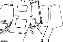
Align the 4 flanged-head bolts at the forward face of the console pad to the 4 keyhole slots in the frame of the console (Figure 31).
-
Move the pad forward until the pad is flush to the console frame (Figure 31).
-
Move the pad down until the flanged-head bolts are seated in the keyhole slots (Figure 31).
-
Tighten the flanged-head bolts to 1978 to 2542 N∙cm (175 to 225 in-lb).
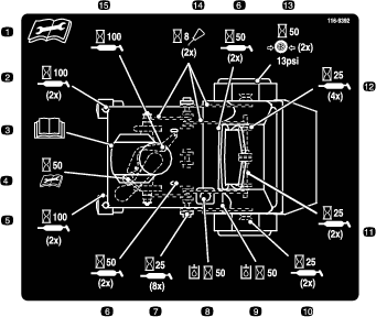
Lubrication
Lubricating the Grease Fittings
| Maintenance Service Interval | Maintenance Procedure |
|---|---|
| Every 25 hours |
|
| Every 50 hours |
|
| Yearly |
|
Grease type: National Lubricating Grease Institute (NGLI) grade #2 multi-purpose gun grease.
Note: Refer to the lubrication chart for service intervals.
| Fitting Locations | Initial Pumps | Number of Places | Service Interval |
|---|---|---|---|
| Front caster pivots | *0 | 2 | Yearly |
| Jackshaft bearings | 1 | 8 | 25 hours |
| Wheel bearings | 1 | 2 | 25 hours |
| Tine shaft bearings | 1 | 4 | 25 hours |
| Tine assembly idlers | 1 | 2 | 25 hours |
| Control pivots | 1 | 4 | 50 hours |
| Belt idler pivot | 1 | 1 | Yearly |
| Front caster hubs | *0 | 2 | Yearly |
-
Shut off the engine, engage the parking brake, wait for all moving parts to stop, and remove the key.
-
Wipe clean the grease fittings with a rag (Figure 32).
-
Connect a grease gun to the fitting (Figure 32).
-
Pump grease into the fittings until grease begins to ooze out of the bearings.
-
Wipe up any excess grease.
Lubricating the Chains
Checking the Condition of the Sprockets
| Maintenance Service Interval | Maintenance Procedure |
|---|---|
| Before each use or daily |
|
-
Shut off the engine, engage the parking brake, wait for all moving parts to stop, and remove the key.
-
Inspect sprockets for wear and replace as required (Figure 33).
Checking the Condition of the Chains
| Maintenance Service Interval | Maintenance Procedure |
|---|---|
| Before each use or daily |
|
-
Shut off the engine, engage the parking brake, wait for all moving parts to stop, and remove the key.
-
Check the chain tension (Figure 33) at both sides of the machine.
Note: The chains should move up and down 6 to 12 mm (1/4 to 1/2 inch).
-
If the chains pop or snap; refer to Adjusting the Jackshaft Drive-Chain Tension, Adjusting the Drive Wheel Chain Tension, or Adjusting the Tine Drive Chain.
Lubricating the Chains
| Maintenance Service Interval | Maintenance Procedure |
|---|---|
| Before each use or daily |
|
Important: Do not lubricate chains with penetrating oil or solvents. Use oil or chain lubricant.
-
Shut off the engine, engage the parking brake, wait for all moving parts to stop, and remove the key.
-
Raise the machine and support it with jack stands with a 460 kg (1,015 lb) capacity.
Caution
Raising the machine for service or maintenance relying solely on mechanical or hydraulic jacks could be dangerous. The mechanical or hydraulic jacks may not be enough support or may malfunction allowing the machine to fall, which could cause injury.
Do not rely solely on mechanical or hydraulic jacks for support. Use adequate jack stands or equivalent support.
-
Start the engine and move the throttle level ahead to the half-throttle position.
Warning
Engine must be running and drive wheels must be turning so adjustments can be performed. Contact with moving parts or hot surfaces may cause personal injury.
Keep your fingers, hands, and clothing clear of rotating components and hot surfaces.
-
Disengage the parking brake.
-
With the engine running, slowly move the motion-control levers forward and lubricate all 6 chains (Figure 33).
-
Check the condition and tension of the chains; refer to Checking the Condition of the Chains.
Lubricating the Casters
Grease type: National Lubricating Grease Institute (NGLI) grade No. 2 multi-purpose gun grease.
Greasing the Caster Pivots
| Maintenance Service Interval | Maintenance Procedure |
|---|---|
| Yearly |
|
-
Remove cap and hex plug from the top of the caster pivot (Figure 34).
-
Thread grease fitting in hole (Figure 34).
-
Pump grease into the fitting until grease oozes out around top bearing (Figure 34).
-
Remove grease fitting and install the plug that you removed in 1 (Figure 34).
-
Install the cap that you removed in step 1 (Figure 34).
-
Repeat steps 1 through 5 to the other caster.
Lubricating the Caster-Hubs Bearings
| Maintenance Service Interval | Maintenance Procedure |
|---|---|
| Yearly |
|
Removing the Caster-Wheel Assembly
-
Shut off the engine, engage the parking brake, wait for all moving parts to stop, and remove the key.
-
Lift the front of the machine and support it with jack stands.
-
Remove the wheel nut and bolt, and remove the caster-wheel assembly from the fork (Figure 35).
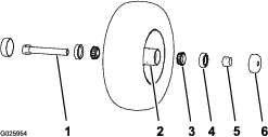
Disassembling the Caster-Wheel Hub and Greasing the Bearings
| Maintenance Service Interval | Maintenance Procedure |
|---|---|
| Yearly |
|
Important: Use new bearing seals when lubricating the caster-wheel hubs.
Important: To prevent seal and bearing damage, check the bearing adjustment often. Spin the caster tire. The tire should not spin freely (more than 1 or 2 revolutions) or have any side play. If the wheel spins freely, adjust torque on spacer nut until there is a slight amount of drag. Apply thread-locking compound.
Grease type: National Lubricating Grease Institute (NGLI) grade No. 2 multi-purpose gun grease.
-
Remove the 2 seal guards from the wheel hub (Figure 36).
-
Remove 1 of the spacer nuts from the axle assembly in the caster wheel (Figure 36).
Note: Note that thread-locking compound has been applied to lock the spacer nuts to the axle (Figure 36).
-
Remove the axle (with the other spacer nut still assembled to it) from the caster-wheel assembly (Figure 36).
-
Pry out both bearing seals (Figure 36).
Note: Discard the old seals.
-
Remove both bearings and inspect them for wear or damage (Figure 36).
Note: Replace the bearing if it is worn or damaged.
-
Pack the 2 bearings with the specified grease.
Assembling the Caster-Wheel Hub
-
Install 1 bearing into the hub of the wheel (Figure 36).
-
Install the bearing seal into the hub at the bearing (Figure 36).
-
If you removed (or broke loose) both of the spacer nuts from the axle assembly, perform the following:
-
Clean the threads of the axle and spacer nut.
-
Apply a thread-locking compound to the threads at 1 end of the axle.
-
Thread the axle nut, with the wrench flats facing outward, onto the end of the axle that is prepared with thread-locking compound (Figure 36).
Note: Do not thread spacer nut all of the way onto the axle. Leave approximately 3 mm (1/8 inch) from the outer surface of the spacer nut to the end of the axle inside the nut.
-
-
Insert the assembled nut and axle into the wheel at the side of the wheel with the new seal and bearing (Figure 36).
-
With the open end of the wheel facing up, fill the area inside wheel cavity (around the axle) with the specified grease.
-
Install the other bearing and new seal into the wheel (Figure 36).
-
Apply a thread-locking compound to the second spacer nut and thread it onto the axle with the wrench flats facing outward.
-
Torque the spacer nut to 8 to 9 N∙m (75 to 80 in-lb), loosen, then torque it 2 to 3 N∙m (20 to 25 in-lb).
Important: Ensure that the axle does not extend beyond either nut.
-
Install the seal guards over the wheel hub (Figure 36).
Installing the Caster-Wheel Assembly
-
Align the hole in the axle of the caster-wheel assembly between the holes in the fork of the caster (Figure 35).
-
Secure the wheel assembly to the fork with the wheel nut and bolt (Figure 35) that you removed in step 3 of Removing the Caster-Wheel Assembly.
-
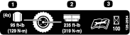
Torque the wheel nut to 91 to 113 N∙m (67 to 83 ft-lb).
Engine Maintenance
Servicing the Air Cleaner
| Maintenance Service Interval | Maintenance Procedure |
|---|---|
| Every 250 hours |
|
| Every 500 hours |
|
Inspect the foam and paper elements, and replace them if they are damaged or excessively dirty.
Important: Do not apply oil to the foam or paper element.
Removing the Foam and Paper Elements
-
Shut off the engine, engage the parking brake, remove the key, and wait for all moving parts to stop before leaving the operating position.
-
Clean around the air cleaner to prevent dirt from getting into the engine and causing damage (Figure 37).
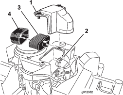
-
Rotate the cover knobs 1/4 turn counterclockwise and remove the air-cleaner cover (Figure 37).
-
Rotate the thumbscrew of the hose clamp counterclockwise until you can separate the air-cleaner assembly from the inlet duct (Figure 37).
-
Carefully pull the foam element off the paper element (Figure 37).
Servicing the Foam Air-Cleaner Element
| Maintenance Service Interval | Maintenance Procedure |
|---|---|
| Every 25 hours |
|
-
Inspect the element for tears, an oily film, or damaged (Figure 37).
Important: Replace the foam element if it is worn or damaged.
-
Wash the foam element in liquid soap and warm water. When the element is clean, rinse it thoroughly.
-
Dry the element by squeezing it in a clean cloth.
Servicing the Paper Air-Cleaner Element
| Maintenance Service Interval | Maintenance Procedure |
|---|---|
| Every 100 hours |
|
| Every 200 hours |
|
Important: Do not wash the paper air-cleaner element.
-
Inspect the element for tears, an oily film, or damage to the rubber seal (Figure 37).
Note: Replace the paper element if it is damaged.
-
Clean the paper element by gently tapping it to remove dust and debris.
Note: If the element is very dirty, replace the air-cleaner element.
Note: Do not use pressurized air to clean the paper element.
Installing the Foam and Paper Elements
Important: To prevent engine damage, always operate the engine with the complete foam and paper air-cleaner assembly installed.
-
Carefully slide the foam element onto the paper air-cleaner element (Figure 37).
-
Align the air-cleaner assembly onto the inlet duct and secure it with the hose clamp (Figure 37).
-
Align the air-cleaner cover onto the engine cover and secure the cover by rotating the cover knobs 1/4 turn clockwise (Figure 37).
Servicing the Engine Oil
Engine-Oil Specifications
Oil Type: Detergent oil (API service SJ or later)
Engine-Oil Capacity: 1.7 L (1.8 US qt) with the filter removed; 1.5 L (1.6 US qt) without the filter removed
Engine-Oil Viscosity: Refer to the table below.
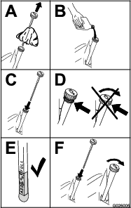
Checking the Engine-Oil Level
| Maintenance Service Interval | Maintenance Procedure |
|---|---|
| Before each use or daily |
|
Important: Do not operate the engine with the oil level below the Low (or Add) mark on the dipstick, or over the Full mark.
-
Park the machine on a level surface, engage the parking brake, shut off the engine, remove the key, and wait for all moving parts to stop before leaving the operating position.
-
Allow the engine to cool.
-
Check the engine-oil level as shown in Figure 39.
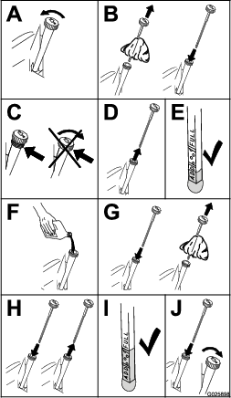
-
If the oil level is low, wipe off the area around the oil fill cap, remove cap and add the specified oil until the oil level is at the Full mark on the dipstick.
Note: Do not overfill the engine with oil.
Changing the Engine Oil
| Maintenance Service Interval | Maintenance Procedure |
|---|---|
| After the first 5 hours |
|
| Every 100 hours |
|
Note: Dispose of the used oil at a recycling center.
-
Park the machine so that the drain side is slightly lower than the opposite side to assure the oil drains completely.
-
Shut off the engine, engage the parking brake, remove the key, and wait for all moving parts to stop before leaving the operating position.
-
Change the engine oil as shown in Figure 41.
Note: Torque drain plug to 27 to 33 N∙m (20 to 24 ft-lb).

-
Slowly pour approximately 80% of the specified oil into the filler tube, and slowly add the additional oil to bring it to the Full mark (Figure 42).
-
Start the engine and drive to a flat area.
-
Check the engine-oil level.
-
Reset the engine-oil service reminder; refer to Resetting the Engine-Oil Maintenance Reminder.
Resetting the Engine-Oil Maintenance Reminder
-
Prepare the machine for maintenance; refer to Preparing the Machine for Maintenance.
Note: You must engage the parking brake to reset the maintenance reminder.
-
Cycle the key switch between the RUN position and the OFF position 4 times within 8 seconds.
The Service Engine screen displays and flashes (Figure 43).
-
Press down the multi-function switch.
The engine-oil maintenance reminder resets to 100.0 (hours), exits the Service Engine screen, and returns to the default screen.
Note: You can exit the Service Engine screen at any time by turning the key to either the OFF or the START positions.
Changing the Engine-Oil Filter
| Maintenance Service Interval | Maintenance Procedure |
|---|---|
| After the first 5 hours |
|
| Every 100 hours |
|
-
Drain the oil from the engine; refer to Changing the Engine Oil.
-
Place a rag under the oil filter to soak up any spilled oil.
Important: Spilled oil may drain under the engine. Wipe up any spilled oil.
-
Change the engine-oil filter (Figure 44).

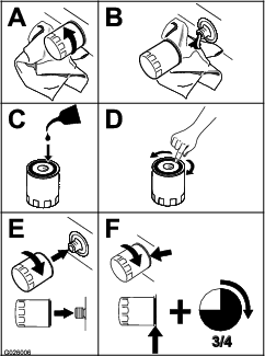
Note: Ensure that the oil-filter gasket touches the engine, and then turn the filter an extra 3/4 turn.
-
Fill the crankcase with the specified type of new oil; refer to Figure 38.
Servicing the Spark Plug
| Maintenance Service Interval | Maintenance Procedure |
|---|---|
| Every 100 hours |
|
Type for all Engines: NGK BPR4ES or equivalent
Air Gap: 0.75 mm (0.03 inch)
Make sure that the air gap between the center and side electrodes is correct before installing the spark plug.
Use a spark plug wrench for removing and installing the spark plug(s) and a gapping tool/feeler gauge to check and adjust the air gap. Install a new spark plug(s) if necessary.
Removing the Spark Plug
-
Shut off the engine, engage the parking brake, remove the key, and wait for all moving parts to stop before leaving the operating position.
-
Remove the spark plug as shown in Figure 45.

Checking the Spark Plug
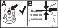
Important: Do not clean the spark plug(s). Always replace the spark plug(s) when it has a black coating, worn electrodes, an oily film, or cracks.
If you see light brown or gray on the insulator, the engine is operating properly. A black coating on the insulator usually means the spark plug is dirty.
Set the gap to 0.75 mm (0.03 inch).
Installing the Spark Plug
Tighten the spark plug(s) to 22 N∙m (16 ft-lb).
Checking the Spark Arrester
Machines with a Spark Arrester Only
| Maintenance Service Interval | Maintenance Procedure |
|---|---|
| Every 50 hours |
|
Warning
Hot exhaust system components may ignite fuel vapors even after the engine is shut off. Hot particles exhausted during engine operation may ignite flammable materials. Fire may result in personal injury or property damage.
Do not refuel or run engine unless spark arrester is installed.
-
Shut off the engine, engage the parking brake, remove the key, and wait for all moving parts to stop before leaving the operating position.
-
Allow the muffler to cool.
-
Check the spark arrester for breaks in the screen or welds.
Note: Replace the spark arrester if it is worn or damaged.
-
If you see that the screen is plugged, perform the following:
-
Remove the spark arrester.
-
Shake loose the particles from the arrester and clean screen with a wire brush.
Note: Soak the arrester screen in solvent if necessary.
-
Install spark arrester onto exhaust outlet.
-
Fuel System Maintenance
Servicing the Fuel Filter
Replacing the Fuel Filter
| Maintenance Service Interval | Maintenance Procedure |
|---|---|
| Every 800 hours |
|
Note: Wipe up any spilled fuel.
-
Shut off the engine, engage the parking brake, remove the key, and wait for all moving parts to stop before leaving the operating position.
-
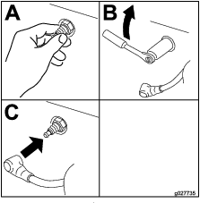
Close the fuel-shutoff valve; refer to Using the Fuel-Shutoff Valve.
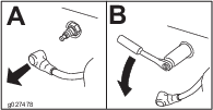
-
Squeeze the ends of the hose clamps together and slide them away from the filter (Figure 48).
-
Remove the filter from the fuel hoses (Figure 48).
Note: Do not install a dirty filter after it is removed from the fuel line.
-
Install a new filter with the flow-direction arrow aligned as illustrated in Figure 48.
Note: Ensure that the fuel hoses are fully seated onto the hose fittings of the fuel filter.
-
Align the hose clamps over the hose and the fuel-filter fittings (Figure 48).
-
Open the fuel-shutoff valve; refer to Using the Fuel-Shutoff Valve.
-
Check for fuel leaks and repair if needed.
-
Wipe up any spilled fuel.
Electrical System Maintenance
Servicing the Battery
| Maintenance Service Interval | Maintenance Procedure |
|---|---|
| Every 100 hours |
|
Always keep the battery clean and fully charged. Use a paper towel to clean the battery case. If the battery terminals are corroded, clean them with a solution of 4 parts water and 1 part baking soda. Apply a light coating of grease to the battery terminals to prevent corrosion.
Voltage: 12 V
Caution
If the key switch is in the ON position, there is potential for sparks and engagement of components. Sparks could cause an explosion or moving parts could accidentally engage, causing personal injury.
Ensure that the key switch is in the OFF position before charging the battery.
Danger
Battery electrolyte contains sulfuric acid, which is fatal if consumed and causes severe burns.
Do not drink electrolyte, and avoid contact with skin, eyes, and clothing. Wear safety glasses to shield your eyes and rubber gloves to protect your hands.
Removing the Battery
Warning
Battery terminals or metal tools could short against metal machine components, causing sparks. Sparks can cause the battery gasses to explode, resulting in personal injury.
-
When removing or installing the battery, do not allow the battery terminals to touch any metal parts of the machine.
-
Do not allow metal tools to short between the battery terminals and metal parts of the machine.
Warning
Incorrect battery-cable routing could damage the machine and cables, causing sparks. Sparks can cause the battery gasses to explode, resulting in personal injury.
-
Always disconnect the negative (black) battery cable before disconnecting the positive (red) cable.
-
Always connect the positive (red) battery cable before connecting the negative (black) cable.
-
Shut off the engine, engage the parking brake, remove the key, and wait for all moving parts to stop before leaving the operating position.
-
Remove the console pad; refer to Removing the Console Pad.
-
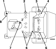
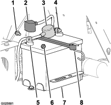
On the battery, lift the black terminal cover from the negative cable (Figure 49).
-
Disconnect the negative battery cable from the negative (-) battery terminal, and remove the cable from the battery (Figure 49).
-
Slide the red terminal cover off the positive battery terminal (Figure 49).
-
Disconnect the positive (red) battery cable, and remove the cable from the battery (Figure 49).
-
Remove the hook of the battery strap from the battery tray (Figure 49), and remove the battery.
Installing the Battery
-
Place the battery onto the machine (Figure 49).
-
Secure the battery to the battery tray with the battery strap.
-
Install the positive (red) battery cable to positive (+) battery terminal with a flanged bolt and flanged nut (Figure 49).
-
Slide the red terminal cover over the positive-battery terminal.
-
Install the negative battery cable and the ground wire to the negative (-) battery terminal with a flanged bolt and flanged nut (Figure 49).
-
Slide the black terminal cover over the negative-battery terminal.
Charging the Battery
Warning
Charging the battery produces gasses that can explode.
Never smoke near the battery and keep sparks and flames away from the battery.
Important: Always keep the battery fully charged (1.265 specific gravity) to prevent battery damage when the temperature is below 0°C (32°F).
-
Remove the battery from the chassis; refer to Removing the Battery.
-
Check the electrolyte level.
-
Ensure that the filler caps are installed on the battery.
-
Charge the battery for 1 hour at 25 to 30 A or 6 hours at 4 to 6 A.
-
When the battery is fully charged, unplug the charger from the electrical outlet, and disconnect the charger leads from the battery posts (Figure 50).
-
Install the battery onto the machine and connect the battery cables; refer to Installing the Battery.
Note: Do not run the machine with the battery disconnected; electrical damage may occur.
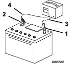
Servicing the Fuses
The electrical system is protected by fuses, and requires no maintenance. If a fuse blows, check the component or circuit for a malfunction or short.
-
Release the cushion from the rear of the machine.
-
Remove the negative-battery cable from the battery terminal.
Note: Ensure that the negative battery cable does not touch the battery terminal.
-
Pull the fuse from the socket of the fuse block (Figure 51).
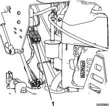
-
Install a fuse of the same type and amperes into the socket of the fuse block (Figure 51).
-
Install the negative-battery cable from the battery terminal; refer to steps 5 and 6 of Installing the Battery.
Drive System Maintenance
Checking the Air Pressure in the Tires
| Maintenance Service Interval | Maintenance Procedure |
|---|---|
| Every 50 hours |
|
Note: The semi-pneumatic caster tires do not need to be inflated.
-
Shut off the engine, engage the parking brake, remove the key, and wait for all moving parts to stop before leaving the operating position.
-
Check the pressure of the drive tires.
-
Inflate the drive tires to 83 to 97 kPa (12 to 14 psi).
Checking the Wheel Hub Nuts
| Maintenance Service Interval | Maintenance Procedure |
|---|---|
| Yearly |
|
Torque the wheel hub nuts (Figure 52) to 285 to 350 N∙m (210 to 260 ft-lb).
Note: Do not use anti-seize compound on the wheel hub.
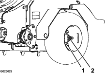
Checking the Torque of the Wheel Lug Nuts
| Maintenance Service Interval | Maintenance Procedure |
|---|---|
| Yearly |
|
Torque the wheel lug nuts (Figure 52) to 122 to 129 N∙m (90 to 95 ft-lb).
Adjusting the Caster Pivot Bearings Pre-Load
Note: If you disassemble the caster pivot bearings, ensure that the spring-disc washers are installed as shown in Figure 53.
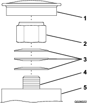
Maintaining the Chain
Adjusting the Jackshaft Drive-Chain Tension
-
Shut off the engine, engage the parking brake, remove the key, and wait for all moving parts to stop before leaving the operating position.
-
Lift the rear of the machine and support it using jack stands or equivalent support.
-
Check the chains on both sides of the machine for proper tension.
Note: The chains should move up and down 6 to 12 mm (1/4 to 1/2 inch).
-
At each side of the machine, loosen the 3 nuts and bolts that secure the transmission mount and tensioner plate, and the 2 nuts securing the adjustment bolt at the tensioner plate as shown in Figure 54.
Note: You must loosen the nuts and bolts that secure the transmission mount and tensioner plate at both sides of the machine.
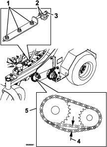
-
Turn the adjustment bolt to move transmission adjustment plates and transmission.
-
When the chains can move up and down 6 to 12 mm (1/4 to 1/2 inch), tighten the nuts on both sides of the adjustment bolts.
-
Tighten nuts and bolts that secure the hydro mounting.
-
Adjust the traction-control linkage, refer to Adjusting the Traction-Control Linkage.
Adjusting the Drive Wheel Chain Tension
-
Shut off the engine, engage the parking brake, remove the key, and wait for all moving parts to stop before leaving the operating position.
-
Lift the rear of the machine and support it using jack stands.
-
Check the tension of the drive-wheel chains (Figure 55).
Note: The chains should move up and down 6 to 12 mm (1/4 to 1/2 inch).
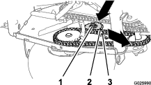
-
Loosen the locknut and carriage bolt that secure the idler sprocket (Figure 55).
-
Increase or decrease chain tension by performing the following:
-
Push down and forward on the sprocket to increase the chain tension as shown in Figure 55.
-
Lift up and back on the sprocket to decrease the chain tension.
-
-
Torque the locknut to 91 to 113 N∙m (67 to 83 ft-lb).
-
Check the chain tension and if necessary repeat steps 4 through 6 until you can move the chain up and down 6 to 12 mm (1/4 to 1/2 inch).
Checking the Torque of the Transmission Output Shaft Nut
| Maintenance Service Interval | Maintenance Procedure |
|---|---|
| Yearly |
|
Torque the nut (Figure 56) on the transmission output tapered shaft to 285 to 353 N∙m (210 to 260 ft-lb).
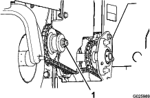
Brake Maintenance
Adjusting the Parking Brake
If the parking brake does not hold securely, an adjustment is required.
-
Park the machine on a level surface.
-
Shut off engine and wait for all moving parts to stop.
-
Check the air pressure in the drive tires.
Note: If needed, adjust to the recommended inflation; refer to Checking the Air Pressure in the Tires.
-
Loosen the jam nut on the brake cable under the console (Figure 57).
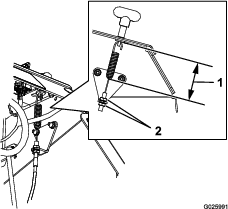
-
Engage the parking brake (Figure 57).
-
Adjust the jam nut position until 7.9 cm (3-1/8 inch) from the bottom of the link to the bottom of the spring (Figure 57).
-
Secure the adjustment of the cable by tightening the jam nuts (Figure 57).
-
Check the parking brake; if necessary, repeat steps 4 through 7.
Adjusting the Brake Switch
-
Park the machine on a level surface.
-
Shut off the engine and wait for all moving parts to stop.
-
Prior the adjusting the brake switch ensure that the parking brake is properly adjusted; refer to Adjusting the Parking Brake.
-
Engage the parking brake.
-
Check the distance between the parking brake-switch bracket to the brake arm of the transmission (Figure 58).
Note: The distance should be 3.2 mm (1/8 inch).
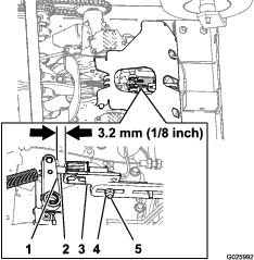
-
If adjustment is required, preform the following:
-
Loosen the locknut and carriage bolt securing the parking brake switch bracket (Figure 58).
-
Adjust the position of the brake-switch bracket until the gap (Figure 58) between the switch bracket and the brake arm is 3.2 mm (1/8 inch)
-
Tighten the locknut and carriage bolt (Figure 58) securing the brake-switch bracket to 1017 to 1243 N∙cm (90 to 110 in-lb).
-
Belt Maintenance
Checking the Condition and Tension of the Belts
| Maintenance Service Interval | Maintenance Procedure |
|---|---|
| Every 50 hours |
|
-
Shut off the engine, engage the parking brake, remove the key, and wait for all moving parts to stop before leaving the operating position.
-
Raise the machine and support it with jack stands with a 460 kg (1,015 lb) capacity.
-
Check the auxiliary pump-drive belt condition and tension (Figure 59).
Note: The belt should deflect 1.3 cm (1/2 inch) when 1.4 kg (3 lb) of force is applied to the belt midway between the auxiliary pump and engine pulleys. If the belt tension is too high or too low, refer to Adjusting the Auxiliary Pump-Drive Belt.
-
Check condition of the transmission-drive belt (Figure 59).
Note: The transmission belt has a automatic-spring tensioner.
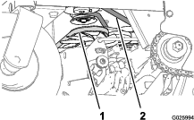
Adjusting the Auxiliary Pump-Drive Belt
-
Shut off the engine, engage the parking brake, remove the key, and wait for all moving parts to stop before leaving the operating position.
-
Loosen the locknut (3/8 inch) that secures the auxiliary pump-idler pulley to the chassis of the machine.
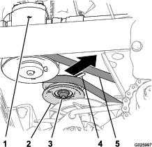
-
Adjust the belt tension as follows:
-
Move the auxiliary pump-idler pulley rearward and outward to tighten the belt.
-
Move the auxiliary pump-idler pulley forward and inward to loosen the belt.
Note: The belt should deflect 1.3 cm (1/2 inch) when 1.4 kg (3 lb) of force is applied to the belt midway between the auxiliary pump and engine pulleys.
-
-
Tighten locknut to 37 to 45 N∙m (27 to 33 ft-lb).
Replacing the Transmission-Drive Belt
Note: No adjustments are required for belt tension.
-
Shut off the engine, engage the parking brake, remove the key, and wait for all moving parts to stop before leaving the operating position.
-
Insert a breaker bar into the socket of the belt-tension bracket and move the bracket outward and forward (Figure 61).
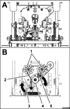
-
Slip the transmission-drive belt of the engine, tensioner, and transmission pulleys (Figure 61).
-
Route the new transmission-drive belt around the engine, tensioner, and transmission pulleys as shown in Figure 61
-
Release the belt-tension bracket and allow the spring to tension the belt (Figure 61).
Note: Make sure that the belt-tension bracket and pulley can move freely.
Controls System Maintenance
Adjusting the Traction-Control Linkage
-
Park the machine on a level surface.
-
Shut off the engine, engage the parking brake, remove the key, and wait for all moving parts to stop before leaving the operating position.
-
Push the control lever all the way forward to the front reference bar.
-
If the control lever contact the reference bar or do not contact the reference bar perform the following:
-
Release the control lever and allow it to return to the neutral position.
-
Remove the spring-clevis pin from the fork fitting of the traction-control linkage (Figure 62).
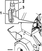
-
Adjust the fork fitting to set the initial gap as follows:
-
Install the spring clevis pin (Figure 62) and move the control lever forward.
-
Repeat this steps 1 through 4 until there is a gap approximately 1.6 mm (1/16 inch) between the control lever and the front reference bar.
-
Remove the spring-clevis pin, rotate the turnbuckle clockwise 1 additional turn, and insert the spring-clevis pin (Figure 62).
-
-
Repeat steps 41 through 46 for the other traction-control linkage.
Hydraulic System Maintenance
Maintaining the Auxiliary Hydraulic System
Hydraulic Fluid Specification
AW-32 hydraulic fluid
Checking the Auxiliary Hydraulic-Fluid Level
| Maintenance Service Interval | Maintenance Procedure |
|---|---|
| Every 50 hours |
|
-
Park the machine on a level surface.
-
Lower the tines to the ground.
-
Shut off the engine, engage the parking brake, remove the key, and wait for all moving parts to stop before leaving the operating position.
-
Remove the console pad; refer to Removing the Console Pad.
-
Clean the area around the hydraulic reservoir cap (Figure 63).
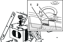
-
Remove the cap and check hydraulic-fluid level in the reservoir (Figure 63).
Note: The hydraulic-fluid level should cover the word Cold that is embossed into the baffle of the reservoir.
-
If necessary, add the specified hydraulic fluid to the reservoir until the fluid covers the Cold fluid level on the baffle (Figure 63).
Note: The baffle ion the reservoir is labeled Hot and Cold. Fill the reservoir to the appropriate level depending upon the temperature of the fluid. The fluid level varies with the temperature of the fluid. The Cold level shows the level of the fluid when it is at 24°C (75°F). The Hot level shows the level of fluid when it is at 107°C (225°F). For example: If the fluid is at ambient-air temperature, about 24°C (75° F), fill only to the Cold level. If the fluid is about 65°C (150° F), fill to halfway between the Hot and Cold levels.
-
Replace the hydraulic reservoir cap and tighten it until it is snug (Figure 63).
Note: Do not overtighten the reservoir cap.
-
Install the console pad; refer to Removing the Console Pad.
Changing the Auxiliary Hydraulic Reservoir Fluid and Filter
| Maintenance Service Interval | Maintenance Procedure |
|---|---|
| After the first 100 hours |
|
| Every 250 hours |
|
-
Shut off the engine, engage the parking brake, remove the key, and wait for all moving parts to stop before leaving the operating position.
-
Carefully clean area around the front of the auxiliary pump, fill cap for the reservoir, and filter (Figure 64).
Important: Ensure that no dirt or contamination enters hydraulic system.
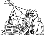
-
At the front of the auxiliary hydraulic pump, remove the inlet hose from the hydraulic fitting in the pump, place the end of the hose in a drain container, and allow the fluid to drain (Figure 65).
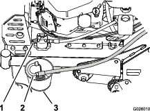
-
Clean around the fitting for the hydraulic pump.
-
Rotate the auxiliary hydraulic filter counterclockwise and remove it from the base of the filter adapter (Figure 66). Allow the fluid to drain.
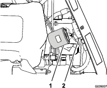
-
Apply a thin coat of specified fluid onto the seal of the new hydraulic filter.
-
Install the filter by rotating it clockwise onto the filter adapter until the seal contacts the filter adapter, then tighten the filter an additional 2/3 to 3/4 turn (Figure 66).
-
Install the inlet hose onto the fitting in the pump and torque the hose fitting to 50 N∙m (37 ft-lb).
-
Add the specified fluid until the level reaches the Cold fill line located on the reservoir tank; refer to Checking the Auxiliary Hydraulic-Fluid Level.
-
Start the engine and raise and lower the tines.
-
Lower the tines to the ground and refill the reservoir to the Cold fill line.
Maintaining the Transmission
Transmission Fluid Specification
Toro® HYPR-OIL™ 500 hydraulic fluid or Mobil® 1 15W-50 synthetic motor oil.
Important: Use the specified fluid. Other fluids could cause system damage.
Checking the Transmission Fluid Level
| Maintenance Service Interval | Maintenance Procedure |
|---|---|
| Every 50 hours |
|
-
Shut off the engine, engage the parking brake, remove the key, and wait for all moving parts to stop before leaving the operating position.
-
Allow the machine to cool.
-
Remove the cap from the expansion tank and check the hydraulic-fluid level in the tank (Figure 67).
Note: The transmission fluid level should cover the Full Cold line molded into the side of the tank.
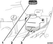
-
If necessary, add the specified transmission fluid until the fluid level is at the Full Cold line of the expansion tank (Figure 67).
-
Replace expansion-tank cap and tighten it until snug.
Important: Do not overtighten the expansion-tank cap.
Changing the Transmission Filters
| Maintenance Service Interval | Maintenance Procedure |
|---|---|
| After the first 100 hours |
|
| Every 250 hours |
|
Note: Do not change the hydraulic system fluid (except for what can be drained when changing filter), unless the fluid has been contaminated or been extremely hot.
-
Shut off the engine, engage the parking brake, remove the key, and wait for all moving parts to stop before leaving the operating position.
-
Raise the machine and support it with jack stands with a 460 kg (1,015 lb) capacity.
-
Remove the 3 washer-head bolts (1/4 x 3/4 inch) that secure the filter guard to the transmission, and remove the guard (Figure 68).
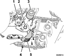
-
Clean the around the transmission filter (Figure 68).
-
Align a drain pan under the filter.
-
Rotate the filter counterclockwise and remove the filter (Figure 68).
Note: Allow the fluid to completely drain from the filter adapter of the transmission.
-
Apply a thin coat of specified fluid onto the seal of the new transmission filter.
-
Install the filter by rotating it clockwise onto the filter adapter until the seal contacts the base of the adapter, then tighten the filter an additional 3/4 to 1 turn (Figure 68).
-
Install the filter guard with the 3 washer-head bolts (1/4 x 3/4 inch) that you removed in step 3 (Figure 68), and tighten the bolts to 1117 to 1243 N∙cm (90 to 110 in-lb).
Filling the Transmissions with Fluid
| Maintenance Service Interval | Maintenance Procedure |
|---|---|
| After the first 100 hours |
|
| Every 250 hours |
|
-
Raise the rear of machine up and support with jack stands (or equivalent support) just high enough to allow the drive wheels to turn freely.
Caution
Raising the machine for service or maintenance relying solely on mechanical or hydraulic jacks could be dangerous. The mechanical or hydraulic jacks may not be enough support or may malfunction allowing the machine to fall, which could cause injury.
Do not rely solely on mechanical or hydraulic jacks for support. Use adequate jack stands or equivalent support.
-
Align a drain pan under the sight plugs of the transmissions (Figure 69 and Figure 70).
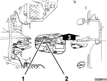
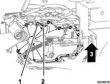
-
At the inboard side of the transmission, near the top, remove the sight plug from 1 of the transmissions (Figure 69 and Figure 70).
-
Add the specified fluid to the expansion tank until fluid flows from the sight-plug port; refer to Checking the Transmission Fluid Level.
-
Install the sight plug and torque it to 244 N∙m (180 in-lb).
-
Repeat steps 3 through 5 for the other transmission.
-
Add the specified fluid into the expansion tank until the fluid level is at the Full Cold line of the tank.
-
Start the engine and move the throttle midway between the SLOW and FAST positions
-
Disengage the parking brake.
-
Slowly move the motion-control levers in the forward and reverse directions 5 to 6 times.
Note: Cycling the traction-controls forward and reverse purges air from the transmissions.
-
Shut off the engine and remove the key.
-
Check the fluid level in the expansion tank, and add the specified fluid as required; refer to Checking the Transmission Fluid Level.
-
Repeat steps 8 through 12 until all the air is completely purged from the transmissions.
Note: The air is purged when the transmissions when the transmissions operate at normal noise levels and smoothly move forward and reverse at normal speeds.
-
Lower the machine and remove the jack stands.
-
Reset the transmission-oil maintenance reminder; refer to Resetting the Transmission-Oil Maintenance Reminder.
Resetting the Transmission-Oil Maintenance Reminder
-
Prepare the machine for maintenance; refer toPreparing the Machine for Maintenance.
Note: You must engage the parking brake to reset the maintenance reminder.
-
Cycle the key switch between the RUN position and the OFF position 6 times within 8 seconds.
The Service Transmission screen displays and flashes (Figure 71).
-
Press down the multi-function switch.
The transmission-oil maintenance reminder resets to 250 (hours), exits the service transmission screen, and returns to the default screen.
Note: You can exit the service transmission screen at any time by turning the key to either the OFF or the START positions.
Tine Maintenance
Checking the Tines
| Maintenance Service Interval | Maintenance Procedure |
|---|---|
| Before each use or daily |
|
-
Shut off the engine, engage the parking brake, remove the key, and wait for all moving parts to stop before leaving the operating position.
-
Raise the machine and support it with jack stands with a 460 kg (1,015 lb) capacity.
Caution
Raising the machine for service or maintenance relying solely on mechanical or hydraulic jacks could be dangerous. The mechanical or hydraulic jacks may not be enough support or may malfunction allowing the machine to fall, which could cause injury.
Do not rely solely on mechanical or hydraulic jacks for support. Use adequate jack stands or equivalent support.
-
Remove the 2 bolts (3/8 x 1 inch) and 2 washers (3/8 inch) that secure the rear-cover panel to the chassis, and remove the panel (Figure 72).
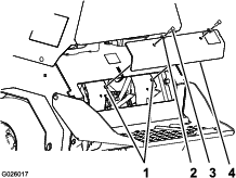
-
Remove rocks and other debris from the tines.
-
Inspect the tines for wear and damage.
Note: Replace any tines that are worn or damaged.
-
Align the holes in the rear-cover panel to the holes in the chassis (Figure 72).
-
Secure the cover panel to the chassis with the 2 bolts and 2 washers (Figure 72) that you removed in step 3, and torque the bolts to 37 to 45 N∙m (27 to 33 in-lb)
Adjusting the Tine Drive Chain
-
Shut off the engine, engage the parking brake, remove the key, and wait for all moving parts to stop before leaving the operating position.
-
Remove the rear cover; refer to step 3 of Checking the Tines.
-
Check the chains on both sides of the machine for proper tension.
Note: The chains should move up and down 6 to 12 mm (1/4 to 1/2 inch).
-
Loosen the locknut and carriage bolt that secure the idler sprocket (Figure 73).
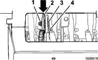
-
Increase or decrease chain tension by performing the following:
-
Push down and forward on the sprocket to increase the chain tension as shown in Figure 73.
-
Lift up and back on the sprocket to decrease the chain tension.
-
-
Torque the locknut to 91 to 113 N∙m (67 to 83 ft-lb).
-
Check the chain tension and if necessary repeat steps 4 through 6 until you can move the chain up and down 6 to 12 mm (1/4 to 1/2 inch).
-
Install the rear panel; refer to steps 6 and 7 of Checking the Tines.
Cleaning
Cleaning the Engine and the Exhaust System Area
| Maintenance Service Interval | Maintenance Procedure |
|---|---|
| Before each use or daily |
|
Caution
Excessive debris around engine cooling air intake and exhaust system area can cause engine, exhaust area, and hydraulic system to overheat, which can create a fire hazard.
Clean all debris from engine and exhaust system area.
-
Shut off the engine, engage the parking brake, remove the key, and wait for all moving parts to stop before leaving the operating position.
-
Clean all debris from screen at the top of the engine, around engine shrouding, and exhaust system area.
-
Wipe up any excessive grease or oil around the engine and exhaust system area.
Removing the Engine Shrouds and Cleaning the Cooling Fins
| Maintenance Service Interval | Maintenance Procedure |
|---|---|
| Every 80 hours |
|
-
Shut off the engine, engage the parking brake, remove the key, and wait for all moving parts to stop before leaving the operating position.
-
Remove cooling shrouds from engine.
-
Clean cooling fins of the engine.
Note: Also clean dust, dirt, and oil from external surfaces of engine, which can cause improper cooling.
-
Install the cooling shrouds into the engine.
Note: Operating the engine without cooling shrouds will cause engine damage due to overheating.
Cleaning the Debris from the Machine
| Maintenance Service Interval | Maintenance Procedure |
|---|---|
| Before each use or daily |
|
-
Shut off the engine, engage the parking brake, remove the key, and wait for all moving parts to stop before leaving the operating position.
-
Clean off any oil, debris, or grass buildup on the machine and aerator deck.
-
Clean off any debris or grass under the chain guards, around the fuel tank, and around the engine and exhaust area.
Waste Disposal
Disposing of the Engine Oil
Engine oil and hydraulic fluid are both pollutants to the environment. Dispose of used oil at a certified recycling center or according to your state and local regulations.
Disposing of the Battery
Danger
Battery electrolyte contains sulfuric acid, which is poisonous and can cause severe burns. Swallowing electrolyte can be fatal or can cause severe burns if it touches skin.
-
Wear safety glasses to shield eyes, and rubber gloves to protect skin and clothing when handling electrolyte.
-
Do not swallow electrolyte.
-
In the event of an accident, flush with water and call a doctor immediately.
Federal law states that batteries should not be placed in the garbage. Management and disposal practices for batteries must follow relevant federal, state, or local laws.
If a battery is being replaced or if the machine containing the battery is no longer operating and is being scrapped, remove the battery and take it to a local certified recycling center. If no local recycling is available return the battery to any certified battery reseller.
Storage
-
Raise the tines, stop the machine, shut off the engine, engage the parking brake, and remove the key.
-
Remove dirt and grime from the entire machine.
Important: You can wash the machine with mild detergent and water. Do not pressure-wash the machine. Avoid excessive use of water, especially near the engine and hydrostatic drive.
-
Service the air cleaner; refer to Servicing the Air Cleaner.
-
Lubricate the machine; refer to Lubrication.
-
Change the engine oil; refer to Changing the Engine Oil.
-
Check and tighten all bolts, nuts, and screws. Repair or replace any part that is damaged.
-
Paint all scratched or bare metal surfaces. Paint is available from your Authorized Service Dealer.
-
Store the machine in a clean, dry garage or storage area.
-
Cover the machine to protect it and keep it clean.
Troubleshooting
Important: Ensure that all operator-safety mechanisms are connected and in operating condition before using the machine.
The following table lists common causes of trouble. Do not attempt to service or replace major items or any items that call for special timing of adjustments procedures (such as valves, governor, etc.). Have this work done by your engine service dealer.
Note: When disconnecting electrical connectors Do not pull on the wires to separate the connectors.
Alert and Error Messages
|
Message |
Icon |
Description |
Resolution |
|---|---|---|---|
|
Voltage Error |
|
The ignition key is in the RUN position and the smart controller/electronic depth control measures that the electrical system is less than 12.3V or greater than 16V. The voltage error icon displays, and the LED status light flashes a red. |
Check the battery, charging system, and wiring. |
|
Valve Solenoid Overcurrent Error |
|
An over-current event occurs at the solenoid valve. The valve solenoid over-current error displays with the number 2 and the LED status light flashes a red. |
Check the valve solenoid and inspect it for damage and wear. |
|
Valve Solenoid Open Error |
|
1 of the 2 valve solenoids or both valve solenoids are disconnected. The valve solenoid open error displays with the number 6 and the LED status light flashes a red. |
Connect the valve solenoid(s). |
|
Valve Solenoid Connection Error |
|
The valve solenoids are connected wrong (the connector for the relief valve is connected to the other valve solenoid). The valve solenoid connection error alert displays, and the tines will not operate until the fault is corrected. |
Swap the valve solenoid connectors. |

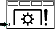

| Problem | Possible Cause | Corrective Action |
|---|---|---|
| The starter does not crank. |
|
|
| The engine does not start, starts hard, or fails to keep running. |
|
|
| The engine loses power. |
|
|
| The engine overheats. |
|
|
| The machine pulls left or right (with levers fully forward). |
|
|
| The machine does not drive. |
|
|
| There is abnormal vibration. |
|
|
| The tines do not raise. |
|
|
Schematics
Electrical Schematic
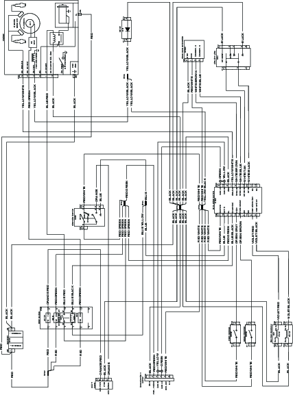
Hydraulic Schematic