Installation

Preparing to Install the Seat Kit

Preparing the Machine

  1. Park the machine on a level surface.

  2. Lower the cutting units.

  3. Engage the parking brake.

  4. Shut off the engine and remove the key.

  5. Wait for all moving parts to stop.

  6. Allow the engine to cool completely.

Raising the Operator’s Platform

  1. Move the platform-latch handle (Figure 1) toward the front of the machine until the latch hooks clear the locking bar.

    g290373
  2. Raise the platform (Figure 2).

    Note: The gas lift cylinder assists lifting the platform.

    g290372

Removing the Storage Compartment

  1. At the left side of the operator’s platform, open the door of the storage compartment (Figure 3).

    g328513
  2. Remove the 3 knobs and 3 washers that secure the storage compartment to the machine, and remove the compartment (Figure 3).

Opening the Hood

Model 31654

Unlatch and open the hood.

Disconnecting the Battery

  1. Loosen the forward nut of the negative battery-cable terminal (Figure 4).

    g344733
  2. Lift the negative battery cable from the battery post (Figure 4).

    Note: Position the negative-battery cable where it cannot contact the negative battery post.

Removing the Existing Seat

Model 31654

Seat weight: 38 kg (84 lb)

Note: Have another person help you remove the seat or use a suitable crane.

  1. Disconnect the connector for the seat-switch wire harness from the connector of the machine wire harness (Figure 5).

    g036778
  2. Route the connector for the seat-switch wire harness through the seat platform and secure the connector to the seat.

  3. Remove the boot from the seat base as follows (Figure 6).

    1. At the sides of the seat-base boot, locate its mounting tabs that protrude through the slot in the channel of the seat base.

      g037076g037047
    2. Pull each tab along the slot until the tab is over the hole and then pull the tab out and away from the seat-base channel.

      Note: Pull the boot forward or rearward depending on which tab you are the removing.

    3. When all of the tabs are removed from their slots, pull the rubber boot down (Figure 7).

  4. While supporting the seat, remove the 4 washers (8 mm) and 4 locknuts (8 mm) that secure the seat to the seat platform (Figure 7).

    Note: Do not remove the 4 bolts (8 x 25 mm) from the holes in the seat and seat platform.

    g036780
  5. Lower the operator’s platform as follows:

    1. Lower the platform carefully.

    2. Move the locking-latch handle toward the front of the mower as the platform nears the fully lowered position.

      Note: This ensures that the latch hooks clear the locking bar.

    3. Fully lower the platform and move the locking handle toward the rear of the mower until the latch hooks fully engage the locking bar.

  6. Remove the seat from the platform.

    Note: Discard the 4 bolts (8 x 25 mm), 4 locknuts (8 mm), and 4 washers (8 mm).

Removing the Existing Seat

Models 31657 and 31659

Seat weight: 38 kg (84 lb)

Note: Have another person help you remove the seat or use a suitable crane.

  1. Disconnect the main wire-harness connector from the control-arm harness (Figure 8).

    Rotate the collar and pull the connector to remove.

    Important: Cover and protect the electrical connectors to prevent damage.

    g343901
  2. Disconnect the seat-switch harness from the seat and leave it on the platform.

  3. Remove the boot from the seat base as follows (Figure 9).

    1. At the sides of the seat-base boot, locate its mounting tabs that protrude through the slot in the channel of the seat base.

      g037076g037047
    2. Pull each tab along the slot until the tab is over the hole and then pull the tab out and away from the seat-base channel.

      Note: Pull the boot forward or rearward depending on which tab you are the removing.

    3. When all of the tabs are removed from their slots, pull the rubber boot up to gain access to the 4 bolts (8 x 25 mm) securing the seat to the platform (Figure 10).

  4. While supporting the seat, remove the 4 locknuts (8 mm) that secure the seat to the seat platform (Figure 10).

    Do not remove the 4 bolts (8 x 25 mm) from the holes in the seat and seat platform.

    g343902
  5. Lower the operator’s platform as follows:

    1. Lower the platform carefully (Figure 11).

      Note: The gas lift cylinder helps support the platform.

      g290371
    2. As the platform nears the fully lowered position, move the platform-latch handle (Figure 12) toward the front of the machine.

      Note: This ensures that the latch hooks clear the locking bar.

      g290369
    3. Fully lower the platform and move the platform-latch handle toward the rear of the machine until the latch hooks fully engage the locking bar (Figure 13).

      g290370
  6. Remove the existing seat with the control arm attached from the platform.

    Note: Discard the 4 bolts (8 x 25 mm) and 4 locknuts (8 mm).

Preparing the New Seat

Model 31654

Parts needed for this procedure:

Seat and suspension assembly1
  1. Remove the covers and bolts that secure the seat belt to the old seat and remove the seat belt (Figure 14).

  2. Remove the nut from the right armrest and remove the right armrest (Figure 14).

    Retain the nut and armrest.

    g347421
  3. Assemble the seat belt onto the new seat and install the previously removed armrest using the previously removed nut (Figure 15).

    Set the armrest to be the same height as the other side.

  4. Torque the seat belt bolts to 70 to 75 N∙m (52 to 55 ft-lb) and install the covers (Figure 15).

    g347420

Preparing the New Seat

Models 31657 and 31659

Parts needed for this procedure:

Seat and suspension assembly1

Removing the Control Arm and Seat Belt from the Seat

  1. Place the seat and control arm onto a bench.

  2. Remove the seat cushion to gain access to the flange nut securing the control arm to the seat (Figure 16).

    g344858
  3. Remove the plastic cover on the left side and loosen the bolt to remove the seat-belt retainer from the seat (Figure 17).

    g344860
  4. Ensure that the control arm is supported sufficiently before removing.

  5. Remove the existing hex-head bolt (7/16 x 2 inches), 2 washers, seat belt, and spacer (Figure 18).

    Retain the hex-head bolt (7/16 x 2 inches), 2 washers, seat belt, and spacer for later installation.

    g344019
  6. Remove the front control arm support plate from the seat.

    Retain the front control arm support plate for later installation.

  7. Remove the hex-head bolt (8 x 10 mm), coupling hex nut (8 mm), and washer (8 mm) from the top of the seat arm (Figure 19).

    Retain the hex-head bolt (8 x 10 mm), coupling hex nut (8 mm), and washer (8 mm) for later installation.

    g345727

Installing the Control Arm and Seat Belt to the New Air Ride Seat

  1. Remove the 3 Phillips-head screws securing the seat cushion and remove the seat cushion (Figure 20).

    This allows access to secure the control arm to the seat.

    g344859
  2. Remove the plastic cover from the left side, loosen the bolt, and secure the seat-belt retainer using the previously removed bolt (Figure 17).

    Apply Loctite® 243 to the bolt and torque the bolt to 70 to 75 N∙m (52 to 55 ft-lb) and install the plastic cover.

  3. Locate the previously removed control arm and brackets.

  4. Secure the previously removed fasteners as shown in Figure 21.

  5. Apply Loctite® 243 to the hex-head bolt (7/16 x 2 inches) and torque the hex-head bolt (7/16 x 2 inches) to 70 to 75 N∙m (52 to 55 ft-lb).

    g344019
  6. Secure the front control arm support plate to the seat (Figure 16).

  7. Secure the previously removed hex-head bolt (8 x 10 mm), coupling hex nut (8 mm), and washer (8 mm) at the top of the seat arm (Figure 19).

  8. Install the previously removed seat cushion.

Installing the Seat

Model 31654

Parts needed for this procedure:

Locknut (8 mm)4
Hex-head bolt (8 x 25 mm)4
  1. At the bottom plate of the new seat, locate the seat-mounting holes for your machine (Figure 22).

    g036928
  2. Assemble the 4 hex-head bolts (8 x 25 mm) to the holes in the flange of the bottom plate (Figure 23) that you identified in step 1.

    g345847
  3. Align the 4 hex-head bolts (8 x 25 mm) of the new seat with the holes in the operators platform (Figure 24).

    g345846
  4. Assemble 2 locknuts (8 mm) to the bolts on the left side of the seat.

  5. Partially raise the operator’s platform to access the threads of the 2 other hex-head bolts (8 x 25 mm).

    Important: Support the seat to prevent it from falling.

  6. Assemble the 2 locknuts (8 mm) to the other 2 hex-head bolts (8 x 25 mm) by hand.

  7. Fully raise the platform.

  8. Torque the hex-head bolts (8 x 25 mm) and locknuts (8 mm) to 27 N∙m (20 ft-lb).

Installing the Seat

Models 31657 and 31659

Parts needed for this procedure:

Hex-head bolt (8 x 25 mm)4
Locknut (8 mm)4
  1. At the bottom plate of the new seat, locate the seat-mounting holes for your machine (Figure 25).

    g344774
  2. Secure the seat assembly to the platform using the 4 hex-head bolts (8 x 25 mm) and 4 locknuts (8 mm) as shown in Figure 26.

    g345728
  3. Fully raise the platform.

  4. Torque the 4 locknuts (8 mm) to 27 N∙m (20 ft-lb).

Connecting the Electrical Components

Parts needed for this procedure:

Standard fuse (10A)—Model 316541
Mini fuse (10 A)—Models 31657 and 316591

Model 31654

  1. Locate the connector labeled AIR-RIDE on the seat behind the rubber boot.

    Locate the air-ride seat connector on the main wire harness breakout and install the connector.

    Note: The breakout of the main wire harness is located by the seat.

  2. Connect the seat-switch connector.

  3. Remove the cover from the fuse block (Figure 27).

    g037069
  4. Insert the standard fuse (10 A) into the 5th fuse position from the left (Figure 28) of the fuse block as follows:

    Note: Ensure that the fuse is fully seated.

    g037201
  5. Install the cover on to the fuse block (Figure 27).

Models 31657 and 31659

  1. Connect the main wire-harness connector to the control arm that you disconnected in Removing the Existing Seat.

  2. Locate the connector labeled AIR-RIDE on the seat behind the rubber boot.

    Locate the air-ride seat connector on the main wire harness breakout and install the connector.

    Note: The breakout of the main wire harness is located by the seat.

  3. Connect the seat-switch connector.

  4. Remove the fuse-block cover located next to the battery (Figure 29)

    g328464
  5. Install the new mini fuse (10 A) into the fuse block (Figure 29).

    Note: Use the decal on the fuse-block cover for the fuse position.

  6. Install the fuse-block cover (Figure 29).

Completing the Seat Kit Installation

Connecting the Battery

  1. Assemble the terminal of the negative battery cable (Figure 30) onto the negative battery post.

    g344733
  2. Tighten the forward nut and T-bolt (Figure 30) of the negative battery cable terminal.

Closing the Hood

Model 31654

Close and latch the hood.

Installing the Storage Compartment

  1. Align the holes on the bottom of the storage compartment with the holes in the chassis brackets.

  2. Assemble the storage compartment to the machine with the 3 knobs and 3 washers (Figure 31).

    g328512
  3. Close the storage-compartment door.

Lowering the Operator’s Platform

Warning

Operating the machine with the platform unlatched may cause you to lose control of the machine, resulting in serious injury to you and bystanders.

Never operate the machine without first checking that the operator platform latching mechanism is fully engaged and in good working order.

  1. Lower the platform carefully (Figure 32).

    Note: The gas lift cylinder helps support the platform.

    g290371
  2. As the platform nears the fully lowered position, move the platform-latch handle (Figure 33) toward the front of the machine.

    Note: This ensures that the latch hooks clear the locking bar.

    g290369
  3. Fully lower the platform and move the platform-latch handle toward the rear of the machine until the latch hooks fully engage the locking bar (Figure 34).

    g290370

Checking the Operator’s Seat Switch

Check that the seat switch in the seat operates correctly; refer to the Operator’s Manual for your machine.

Product Overview

Seat Controls

Seat-Adjustment Lever

Move the seat-adjustment lever on the side of the seat outward, slide the seat to the desired position, and release the lever to lock the seat into position (Figure 35).

g037412

Armrest-Adjustment Knob

Rotate the knob to adjust the armrest angle (Figure 35).

Seat-Back-Adjustment Lever

Move the lever to adjust the seat-back angle (Figure 35).

Weight and Height Gauge

The weight and height gauge indicates when the seat is adjusted correctly (Figure 35).

Weight and Height Adjustment Lever

Use this lever to adjust to the proper weight of the operator (Figure 35). Pull up the lever to increase the air pressure and push down to decrease the air pressure. The proper adjustment is correct when the weight and height gauge is in the green region.

Also use this lever to adjust the height of the seat. Position the suspension anywhere within the green region on the gauge to adjust the height.

Maintenance

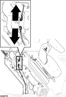
Greasing the Seat Suspension Mechanism

Maintenance Service IntervalMaintenance Procedure
Yearly
  • Grease the pivot points of the seat-suspension mechanism.
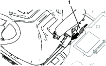
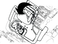
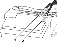
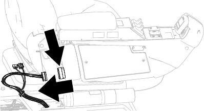
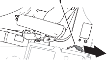
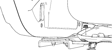
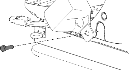
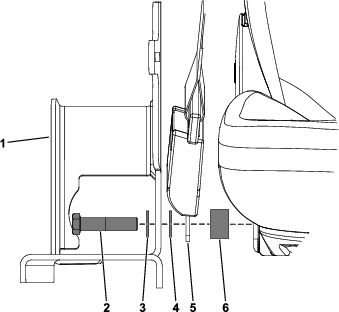
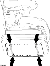
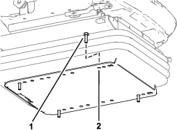
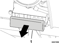
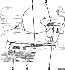
    1. Pull back the rubber boot from the channel of the seat base.

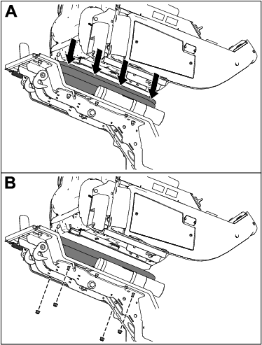
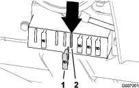
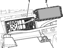
    2. Apply good quality grease to all pivot points of the suspension mechanism.

    3. Install the boot onto the channel of the seat base.

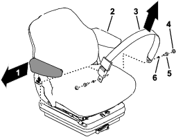
    Maintaining the Seat Belt

    There are no field-serviceable parts on the seat belt. If it shows signs of wear, damage, or malfunction, replace the seat belt assembly.
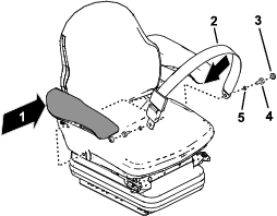
    Cleaning the Seat

    Important: Do not clean the seat with a pressure washer.

    Note: Keep the surfaces of the operator's seat clean.

    Caution

    Use caution when cleaning the backrest—unintentionally moving backrest-tilt lever may cause the backrest to rotate forward unexpectedly and cause injury.

    When cleaning the backrest cushion, firmly hold the backrest when operating the backrest-tilt lever.

    • You do not need to remove the upholstery from the seat frame for cleaning.

    • While cleaning the upholstery, do not allow cleaning solution to soak through the upholstery surfaces.

    • Use commercially available upholstery or plastic cleaning solution. Before using a new cleaning solution, test it for compatibility with the upholstery on a small concealed area of the seat.