


Maintenance
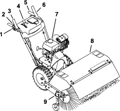
Note: Determine the left and right sides of the machine from the normal operating position.
Recommended Maintenance Schedule(s)
| Maintenance Service Interval | Maintenance Procedure |
|---|---|
| After the first 2 hours |
|
| After the first 5 hours |
|
| Before each use or daily |
|
| Every 50 hours |
|
| Every 100 hours |
|
| Every 200 hours |
|
| Every 300 hours |
|
| Yearly |
|
| Yearly or before storage |
|
Important: Refer to your engine owner's manual for additional maintenance procedures. For engine adjustments, repairs, or warranty service not covered in this manual, contact the authorized engine service dealer.
Maintenance Safety
Read the following safety precautions before performing any maintenance on the machine:
-
Before servicing, adjusting, or cleaning the machine, shut off the engine and wait for all moving parts to stop. If major repairs are ever needed, contact your Authorized Service Dealer.
-
Always wear eye protection while performing an adjustment or repair to protect your eyes from foreign objects that the machine may throw.
-
Check all fasteners at frequent intervals for proper tightness to ensure that the machine is in safe working condition.
-
Do not change the governor settings on the engine.
-
Purchase only genuine Toro replacement parts and accessories.
Preparing for Maintenance
-
Move the machine to a level surface.
-
Shut off the engine and allow it to cool.
-
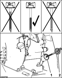
Disconnect the spark-plug wire from the spark plug and keep the wire away from the plug, to prevent accidental starting (Figure 22).
Lubrication
Lubricating the Broom-Angle-Lock Pin and the Hex Shaft
| Maintenance Service Interval | Maintenance Procedure |
|---|---|
| Every 100 hours |
|
| Yearly |
|
-
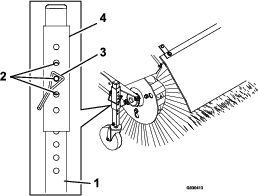
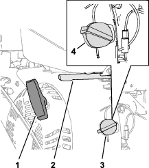
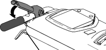
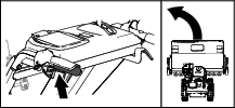
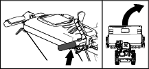
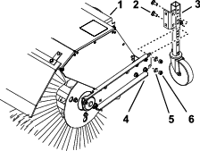
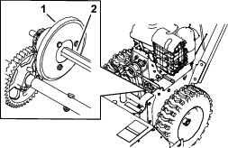
Lubricate the broom-angle-lock pin fitting with No. 2 lithium grease (Figure 23).
-
Remove the belt cover and the engine shield.
-
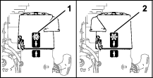
Move the speed-selector lever to the R2 position.
-
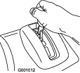
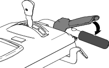
Dip a long, clean, small-tipped paint brush in automotive engine oil and lightly lubricate the hex shaft (Figure 24).
Important: Do not get oil on the rubber wheel or the aluminum friction-drive plate as the traction drive will slip (Figure 24).
Note: Rock the machine forward and rearward to rotate the hex shaft.
-
Move the speed selector lever to position 6.
-
Lubricate the other end of the hex shaft.
-
Move the speed selector lever forward and rearward a few times.
-
Install the belt cover and the engine shield.
Engine Maintenance
Servicing the Air Cleaner
| Maintenance Service Interval | Maintenance Procedure |
|---|---|
| Every 50 hours |
|
| Every 200 hours |
|
| Every 300 hours |
|
Important: Do not operate the engine without the air filter assembly; extreme engine damage may occur.
-
Release the latches on the cover for the air cleaner.
-
Remove the cover and clean it thoroughly ().
Note: Be careful to prevent dirt and debris from falling into the base.
-
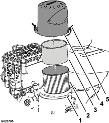
Remove the foam pre-cleaner, wash it with a mild detergent and water, and then blot it dry (Figure 25).
-
Remove and inspect the paper air filter (); discard it if it is excessively dirty.
Important: Do not try to clean a paper filter.
-
Wipe dirt away from the base and the cover with a moist rag.
Note: Be careful to prevent dirt and debris from entering the air duct leading to the carburetor.
-
Install the foam pre-cleaner onto the paper air filter (Figure 25).
Note: Use a new paper air filter if you discarded the old one.
-
Install the air filter assembly to the air-filter base (Figure 25).
-
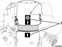
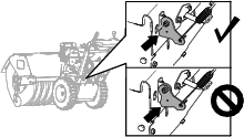
Align the arrow decal on the air-cleaner cover and the arrow decal on the base (Figure 26).
-
Secure the air-filter cover to the base with the latches.
Checking the Engine-Oil Level
| Maintenance Service Interval | Maintenance Procedure |
|---|---|
| Before each use or daily |
|
Engine Oil Type: Toro 4–Cycle Premium Engine Oil
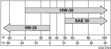
Use high-quality detergent oils (including synthetic) of API (American Petroleum Institute) service class SJ or higher. Select the viscosity based on the air temperature at time of operation as shown in the table below.
Check the oil level when the engine is cold.
-
Clean the area around the dipstick.
-
Remove the dipstick and read the oil level (Figure 28).
-
Remove the dipstick and wipe off the oil with a clean rag.
-
Insert the dipstick into the filler neck, rest it on the oil filler neck, and turn it counterclockwise until the cap drops down to lowest point of the thread leads.
Note: Do not thread the cap onto the tube.
-
Remove dipstick and check oil level.
Note: Do not operate the engine with the oil level below the Add mark or above the Full mark on the dipstick.
Note: The oil level should be at top of the indicator on the dipstick (Figure 28).
-
If the oil level is low, perform the following:
-
Pour the specified oil into the filler neck (Figure 28).
Note: Do not overfill the engine with oil.
-
Repeat steps 3 through 5.
-
-
If the oil level is high, preform the following:
-
Remove the cap from the drain fitting.
-
Drain the oil until the oil level is at the top of the indicator on dipstick; refer to steps 1 of Changing the Engine Oil.
-
Install the cap onto the drain fitting; refer to step 2 of Changing the Engine Oil.
-
-
-
Insert the dipstick into the filler neck and tighten the dipstick by hand.
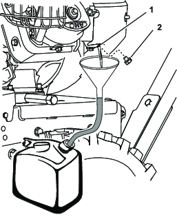
Changing the Engine Oil
| Maintenance Service Interval | Maintenance Procedure |
|---|---|
| After the first 5 hours |
|
| Every 100 hours |
|
Oil capacity: 0.60 L (0.63 qt)
Note: Drain the engine oil while the engine is warm.
-
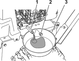
Place a pan under drain fitting and remove the oil-drain cap (Figure 29).
-
Allow the oil to drain and then install the oil-drain cap.
-
Clean around the filler neck and remove the dipstick.
-
Fill to the specified capacity with the specified oil and replace the dipstick; refer to Checking the Engine-Oil Level.
Note: Do not overfill the engine with oil.
-
Wipe up any spilled oil.
-
Start the engine and check for leaks.
-
Shut off the engine and check the oil level; refer to Checking the Engine-Oil Level.
Checking the Spark Plug
| Maintenance Service Interval | Maintenance Procedure |
|---|---|
| Every 100 hours |
|
Spark plug type: Champion® RC12YC, Kohler® 12 132 02-S, or Kohler 25 132 14-S (RFI compliant)
Spark-plug gap: 0.76 mm (0.030 inch)
-
Disconnect the spark-plug wire from the terminal of the spark plug (Figure 22).
-
Clean the area around the base of the spark plug.
-
Remove the spark plug from the cylinder head by rotating the plug counterclockwise.
-
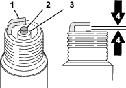
Examine the plug for wear and damage (Figure 30).
Important: Replace a cracked, fouled, or dirty spark plug. Do not clean the electrodes, because grit entering the cylinder can damage the engine.
-
Check the spark-plug gap with a wire gauge (Figure 30).
Note: If necessary, adjust the gap to 0.76 mm (0.030 inch) by carefully bending the ground electrode.
-
Install the spark plug by threading it into the cylinder head, and torque the plug to 20 N∙m (14 lb-ft).
-
Connect the spark-plug wire to the terminal of the spark plug.
Fuel System Maintenance
Draining the Fuel System
| Maintenance Service Interval | Maintenance Procedure |
|---|---|
| Yearly or before storage |
|
-
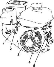
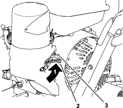
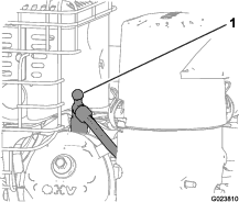
Locate the drain bolt that is in the side port of the carburetor bowl (Figure 31).
-
Align the equipment that you will use to collect the fuel beneath the drain screw.
-
Remove the drain screw from the carburetor and allow the fuel to drain from the fuel tank and the carburetor.
Note: Do not remove the bowl-retaining screw from carburetor.
-
Install the drain bolt into the side port of the carburetor.
-
Start the engine and run it until it runs out of fuel.
Drive System Maintenance
Checking the Tire Air Pressure
| Maintenance Service Interval | Maintenance Procedure |
|---|---|
| Every 50 hours |
|
| Yearly or before storage |
|
-
Shut off the engine, wait for all moving parts to stop, and leave engine switch in the OFF position.
-
Measure the tire air pressure in the drive tires.
Important: The tire air pressure should measure 117 to 138 kPa (17 to 20 psi).
-
Add air to or remove air from the drive tires until you measure to 117 to 138 kPa (17 to 20 psi).
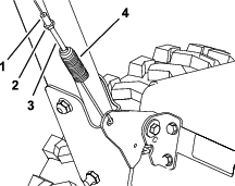
Checking the Traction Cable Adjustment
| Maintenance Service Interval | Maintenance Procedure |
|---|---|
| After the first 2 hours |
|
| Yearly |
|
Important: If the machine does not drive in the forward or reverse speeds or it drives when you release the traction lever, adjust the traction cable; refer to Adjusting the Traction Cable.
-
Disengage the traction level.
-
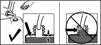
Check the clearance between the bottom of the traction-cable bracket and the top plate of the machine (Figure 33).
Note: The traction-cable bracket should touch the top plate.
-
If the traction-cable bracket does not touch the top plate, adjust the traction cable; refer to Adjusting the Traction Cable.
Broom Maintenance
Checking the Broom-Shaft Shear Pin
| Maintenance Service Interval | Maintenance Procedure |
|---|---|
| Before each use or daily |
|
-
Move the machine to a level surface.
-
Shut off the engine, wait for all moving parts to stop, and disconnect the spark-plug wire.
-
Check the shear pin located on the broom shaft on either side of the gearbox.
-
If the shear pin is damaged, remove the pin, replace it, and secure the it with a nut.
Replacing Worn or Damaged Broom Segments
Service Interval: As required.
-
Raise the broom by setting the caster positions.
-
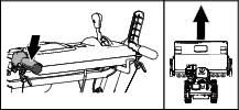
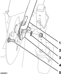
On both sides of the machine, remove and retain the carriage bolts, washers, and locknuts that secure the end bearings to the broom support.
-
Manually pull the power unit rearward to remove the broom assembly from the machine.
-
Support the spline shaft on either side of the gearbox.
-
Stand the broom core assembly on end so that the end retainer plate faces upward (Figure 38).
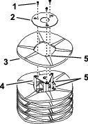
-
Remove and retain the hardware from the end-retainer plate (Figure 38).
-
Remove the damaged broom segment(s).
-
Install the new segment(s) by staggering the metal ring alignment fingers as shown in Figure 38.
Important: You may damage the broom assembly if you do not properly install the broom segments.
-
Install the broom assembly onto the machine.
Important: Make sure that the bearing setscrews are tightened before operating the broom.
Checking the Broom Drive Adjustment
| Maintenance Service Interval | Maintenance Procedure |
|---|---|
| After the first 2 hours |
|
| Yearly |
|
-
Remove the belt cover; refer to Removing the Belt Cover.
-
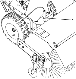
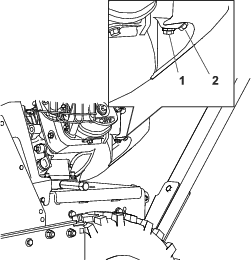
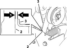
With the broom drive lever disengaged, ensure that the gap between the broom clutch arm and the frame of the machine is 1.5 mm (1/16 inch) as shown in Figure 39.
Important: If the gap between the broom clutch arm and the frame is too small or too large, adjust the broom drive cable; refer to Adjusting the Broom Drive Cable.
-
If the gap between the broom clutch arm and the frame is 1.5 mm (1/16 inch), install the belt cover; refer to Installing the Belt Cover.
Adjusting the Broom Drive Cable
-
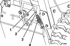
Loosen the jam nut (Figure 40).
-
Rotate the spring-tension adjuster until you measure a 1.5 mm (1/16 inch) gap between the frame and the broom clutch arm ( Figure 40 and Figure 41).
-
Tighten the jam nut (Figure 40).
-
Install the belt cover; refer to Installing the Belt Cover.
Important: If the broom cable is properly adjusted but a problem remains, contact your Authorized Service Dealer.
Belt Maintenance
Removing the Belt Cover
-
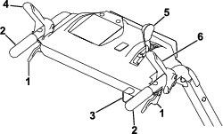
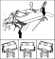
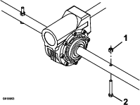
Loosen the 2 flange-head screws that secure the belt cover to the machine (Figure 42).
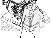
-
Remove the cover from the machine.
Installing the Belt Cover
Checking the Condition of the Belts
| Maintenance Service Interval | Maintenance Procedure |
|---|---|
| Every 50 hours |
|
-
Remove the belt cover; refer to Removing the Belt Cover.
-
Check the 2 belts for damage or wear.
Note: Replace damaged or excessively worn belt(s); refer to Replacing the Broom Drive Belt and Replacing the Traction Belt.
-
Install the belt cover; refer to Installing the Belt Cover.
Replacing the Broom Drive Belt
Removing the Broom-Drive Belt
-
Park the machine on a level surface, shut off the engine, and wait for all moving parts to stop.
-
Remove the belt cover; refer to Removing the Belt Cover.
-
Remove the 2 flange capscrews that secure the belt guide, and remove the guide from the engine (Figure 44).
Important: Do not bend the belt guide while removing it.
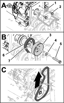
-
Remove the capscrew (3/8 x 2 inches) and washer that secures the broom-drive pulley to the crankshaft of the engine, and remove the pulley (Figure 44).
Note: If necessary, hold the pulley spacer between the broom-drive pulley and engine to keep the crankshaft from turning.You do not need to remove the pulley spacer from the crankshaft.
-
Slip the broom-drive belt 96 cm (37-1/4 inch) off the driveshaft pulley, and remove the belt from the machine.
Installing the Broom Drive Belt
Owner provided materials: medium-strength thread-locking compound
-
Assemble the washer over the capscrew (3/8 x 2 inches), and apply a coat of medium-strength thread-locking compound to the threads of the capscrew.
-
Assemble the belt 96 cm (37-1/4 inch) into the groove of the driveshaft pulley (Figure 45).
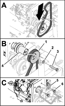
-
Assemble the belt into the groove of the broom-drive pulley (Figure 45).
-
Assemble the broom-drive pulley onto the pulley spacer (Figure 45).
Important: Align the drive keys of the spacer with the slots in the pulley.
-
Secure the pulley and spacer to the driveshaft (Figure 45) with the capscrew (3/8 x 2 inches).
-
Torque the capscrew to 42 to 52 N∙m (31 to 39 ft-lb).
-
Assemble the belt guide to the engine with the 2 flange capscrew (Figure 45).
-
Torque the capscrews to 23 to 29 N∙m (17 to 21 ft-lb).
-
Install the belt cover; refer to Installing the Belt Cover.
Replacing the Traction Belt
Removing the Traction Belt
-
Drain the fuel system; refer to Draining the Fuel System.
-
Remove the belt cover; refer to Removing the Belt Cover.
-
Remove the broom-drive belt; refer to Removing the Broom-Drive Belt.
-
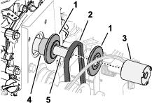
Remove the pulley spacer, the forward sheave half, and traction belt 87.6 cm (34-1/2 inches) from the crankshaft of the engine (Figure 46).
-
At the back of the machine, loosen the 2 top flange-head capscrew (1/4 x 5/8 inch) that secure the rear cover to the machine (Figure 47).
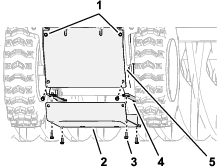
-
Remove the 6 flange-head capscrew (1/4 x 5/8 inch) that secure the bottom cover to the machine, and remove the cover (Figure 47).
-
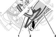
Slip the traction belt between the friction wheel and the traction pulley, and remove the belt from the machine (Figure 48).
Installing the Traction Belt
-
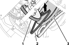
Slip the traction belt between the friction wheel and the traction pulley, and into the machine (Figure 49).
-
At the top of the machine, align the traction belt into the groove of the traction pulley, and slip the traction belt over the crankshaft of the engine (Figure 50).
-
Install the broom drive belt; refer to Installing the Broom Drive Belt.
-
At the bottom of the machine, align the holes in the bottom cover with the holes in the flanges of the left and right side plates (Figure 51).
Note: Ensure that the rear cover overlaps the bottom cover.
-
Assemble the bottom cover to the machine (Figure 51) with the 6 flange-head capscrew (1/4 x 5/8 inch).
-
tighten the 2 top flange-head capscrew (1/4 x 5/8 inch) that secure the rear cover to the machine (Figure 51).
Chassis Maintenance
Checking for Loose Hardware
| Maintenance Service Interval | Maintenance Procedure |
|---|---|
| Before each use or daily |
|
-
Inspect the machine for any loose hardware, missing hardware, or any other possible problem.
-
Tighten all loose hardware before operating the machine.
-
Replace any missing hardware before operating the machine.