
Maintenance
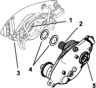
Changing the Gearbox Lubricant
| Service Interval |
| After the first 100 hours |
| Every 500 hours / Yearly (Whichever comes first) |
-
Clean the external surfaces of the groomer housing.
Important: Ensure that there is no dirt or clippings on the outside of the groomer housing; if debris gets inside of the groomer it can damage the gearbox.
-
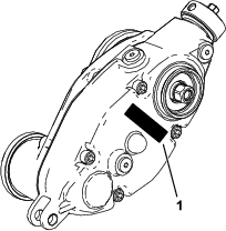
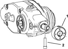
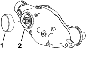
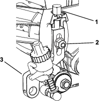
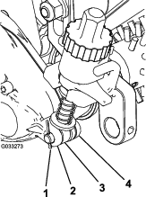
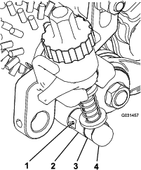
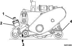
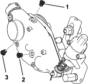
Remove the drain plug on the bottom of the housing (Figure 32).
-
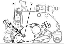
Remove the fill plug on the side of the housing and loosen the air vent plug on the top so air can pass through (Figure 32).
-
Align a suitable container beneath the oil drain port to catch drained oil.
-
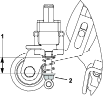
Tip the cutting unit vertically until the drain port is at the bottom to ensure complete drainage (Figure 30).
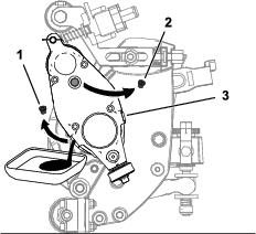
-
Rock the cutting unit back and forth to ensure complete drainage. When the oil is completely drained, place the cutting unit on a level surface.
-
Install the drain plug.
-
Use a syringe (Part No. 137-0872) to fill the drive box with 50 cc of 80-90W oil.
-
Install the fill plug and tighten the air-vent plug.
-
Torque all plugs to 3.62 to 4.75 N∙m (32 to 42 in-lb).
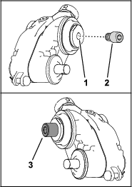
Cleaning the Grooming Reel
| Maintenance Service Interval | Maintenance Procedure |
|---|---|
| After each use |
Clean off the grooming reel after using it by spraying it with water. Do not direct the water stream directly at the groomer bearing seals. Do not permit the grooming reel to stand in water so that the components rust.
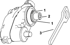
Inspecting the Blades
| Maintenance Service Interval | Maintenance Procedure |
|---|---|
| Before each use or daily |
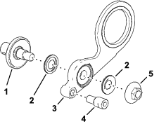
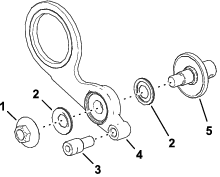
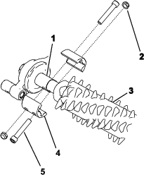
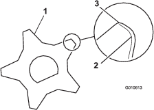
Inspect the grooming-reel blades frequently for damage and wear. Straighten bent blades with a pliers. Replace worn blades, and torque the locknuts to 42 to 49 N∙m (31 to 36 ft-lb). When inspecting the blades, check to see that nuts on the right and left blade-shaft ends are tight.
Note: If you are using spring steel blades, when 1 side of the blades become worn, remove the grooming reel, rotate it 180 degrees, and install it so that the unworn side is facing the direction of rotation.
Note: Because the groomer may introduce more debris (i.e., dirt and sand) into the cutting unit than what the reel would normally be exposed to, check the bedknife and main reel for wear more frequently. This is especially important in sandy soil and/or when the groomer is set for penetration.
Restraining the Reel
Warning
The cutting reel blades are sharp and capable of amputating hands and feet.
-
Keep your hands and feet outside of the reel.
-
Ensure that the reel is restrained before servicing it.
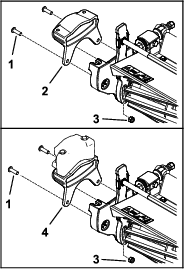
Restraining the Reel for Removing Threaded Inserts
-
Tip up the cutting unit so that you access the bottom of the reel.
-
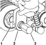
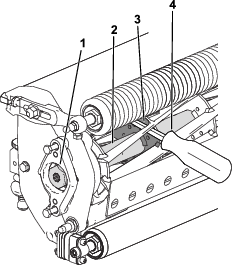
Insert a long-handled pry bar (recommended 3/8 x 12 inches with a screwdriver handle) through the bottom of the cutting reel, closest to the side of the cutting unit that you will be torquing (Figure 34).
-
Place the pry bar against the weld side of the reel support plate (Figure 34).
Note: Insert the pry bar between the top of the reel shaft and the backs of the reel blades so that the reel will not move.
Important: Do not contact the cutting edge of any blades with the pry bar; this may damage the cutting edge and/or cause a high blade.
Important: The insert on the left side of the cutting unit has left-hand threads. The insert on the right side of the cutting unit has right-hand threads.
-
Rest the handle of the pry bar against the roller.
-
Complete the removal of the threaded insert while ensuring that the pry bar stays in place, then remove the pry bar.
-
Lower the cutting unit to rest on the rollers.
Restraining the Reel for Installing Threaded Inserts
-
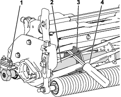
Insert a long-handled pry bar (recommended 3/8 x 12 inches with a screwdriver handle) through the front of the cutting reel, closest to the side of the cutting unit that you will be torquing (Figure 35).
-
Place the pry bar against the weld side of the reel support plate (Figure 35).
Note: Insert the pry bar between the top of the reel shaft and the backs of the reel blades so that the reel will not move.
Important: Do not contact the cutting edge of any blades with the pry bar; this may damage the cutting edge or cause a high blade.
Important: The insert on the left side of the cutting unit has left-hand threads. The insert on the right side of the cutting unit has right-hand threads.
-
Rest the handle of the pry bar against the roller.
-
Follow the installation instructions for the threaded inserts to install them while keeping the pry bar in place. Torque the insert as recommended.
-
Remove the pry bar.