Installation
This kit automatically prevents uneven settling of the mower decks.
Note: Determine the left and right sides of the machine from the normal operating position.
Installing a Deck-Lock Manifold for the Number 1 Lift Arm
Parts needed for this procedure:
| Right manifold assembly (Part No. 119-8631) | 1 |
| Straight hydraulic fitting | 1 |
| 90-degree hydraulic fitting | 1 |
| Self tapping screw (1/4 x 1-3/4 inch) | 2 |
| Hydraulic hose | 1 |
-
Park the machine on a level surface, lower the cutting decks, apply the parking brake, shut off the engine and remove the key.
-
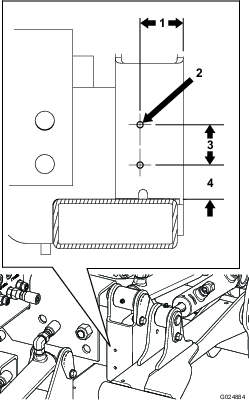
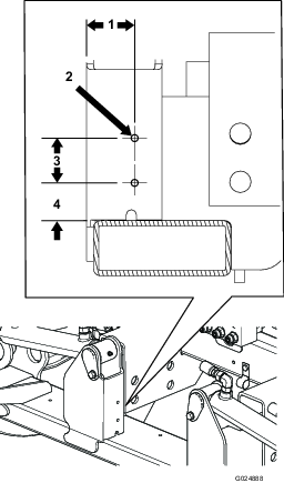
Using the dimensions shown in Figure 1, locate, mark and drill 2 holes (0.221 or 0.228 inch, #1 or #2 drill size) in the traction unit frame tube for the number 5 lift arm. Drill through only 1 wall of the tube.
Note: Use of a 90° drill is recommended.
-
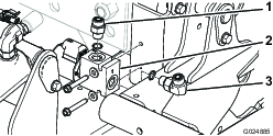
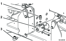
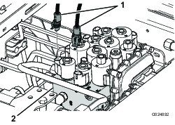
Mount the right deck-lock manifold to the frame tube with 2 self tapping screws (1/4 x 1-3/4 inch). Position the manifold as shown in Figure 2.
-
Install the straight hydraulic fitting into the top of the manifold (Figure 2).
-
Install the 90-degree hydraulic fitting into the end of the manifold (Figure 2).
-
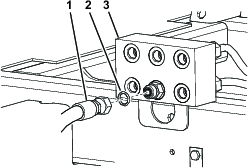
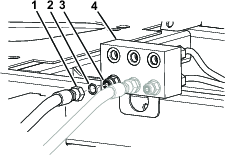
Place a drain pan under the junction manifold (Figure 3).
-
Disconnect the hydraulic hose from the lower center fitting on the junction manifold (Figure 3).
-
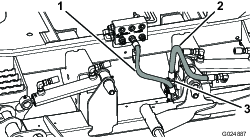
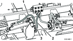
Route and install the end of the hose disconnected from the junction manifold fitting to the top (straight) fitting on the deck-lock manifold (Figure 4).
Note: Make sure that all O-rings are in place and lubricated with hydraulic fluid before installation.
-
Route and install the new hose to the junction manifold and the 90-degree deck-lock manifold fitting (Figure 4).
Important: Make sure the hose from the junction manifold to the deck-lock manifold does not contact the number 1 lift arm.
Installing a Deck-Lock Manifold for the Number 5 Lift Arm
Parts needed for this procedure:
| Left manifold assembly (Part no. 119-8639) | 1 |
| Straight hydraulic fitting | 1 |
| 90-degree hydraulic fitting | 1 |
| Self tapping screw (1/4 x 1-3/4 inch) | 2 |
| Hydraulic hose | 1 |
-
Using the dimensions shown in Figure 5, locate, mark and drill 2 holes (0.221 or 0.228 inch, #1 or #2 drill size) in the traction unit frame tube for the number 5 lift arm. Drill through only 1 wall of the tube.
-
Mount the left deck-lock manifold to the frame tube with 2 self tapping screws (1/4 x 1-3/4 inch). Position the manifold as shown in Figure 6.
-
Install the straight hydraulic fitting into the top of the manifold (Figure 6).
-
Install the 90 degree hydraulic fitting into the end of the manifold (Figure 6).
-
Place a drain pan under the junction manifold (Figure 7).
-
Disconnect the hydraulic hose from the lower left fitting on the junction manifold (Figure 7).
-
Route and install the end of the hose disconnected from the junction manifold fitting to the top (straight) fitting on the deck-lock manifold (Figure 8).
Note: Make sure that all O-rings are in place and lubricated with hydraulic fluid before installation.
-
Route and install the new hose to the junction manifold and 90-degree, deck-lock manifold fitting (Figure 8).
Important: Make sure that the hose from the junction manifold to the deck-lock manifold does not contact the number 5 lift arm.
Installing the Wire Harness
Parts needed for this procedure:
| Wire harness | 1 |
| Cable tie | 4 |
-
Unlatch and raise the seat. Secure the seat with the prop rod.
-
Disconnect the electrical connector from the S5 solenoid on the lift manifold (Figure 9) and connect it to the connector on the deck-lock harness labeled S5 HARNESS.
-
Plug the connector on the deck-lock harness labeled S5 SOLENOID to the S5 solenoid on the lift manifold (Figure 9).
-
Disconnect the electrical connector from the S6 solenoid on the lift manifold (Figure 9) and plug it to the connector on the deck-lock harness labeled S6 harness.
-
Plug the connector on the deck-lock harness labeled S6 SOLENOID to the S6 solenoid on the lift manifold.
-
Route and plug the appropriate connector on the deck-lock harness labeled DECK-LOCK SOLENOID to the solenoid on the rear of each deck-lock manifold.
-
Secure the harness away from any sharp, hot or moving components with cable ties.
-
Disengage the seat prop and lower the seat.