
 ,
which means Caution, Warning, or Danger—personal safety instruction.
Failure to comply with these instructions may result in personal injury
or death.
,
which means Caution, Warning, or Danger—personal safety instruction.
Failure to comply with these instructions may result in personal injury
or death.


Maintenance
Note: Determine the left and right sides of the machine from the normal operating position.Download a free copy of the electrical or hydraulic schematic by visiting www.Toro.com and searching for your machine from the Manuals link on the home page.
Important: Refer to your engine Operator's Manual for additional maintenance procedures.
Caution
If you leave the key in the ignition switch, someone could accidently start the engine and seriously injure you or other bystanders.
Remove the key from the ignition before you do any maintenance.
Maintenance Safety
-
Park the machine on a level surface, disengage the auxiliary hydraulics, lower the attachment, engage the parking brake (if equipped), shut off the engine, and remove the key. Wait for all movement to stop and allow the machine to cool before adjusting, cleaning, storing, or repairing it.
-
Clean up oil or fuel spills.
-
Do not allow untrained personnel to service the machine.
-
Use jack stands to support the components when required.
-
Carefully release pressure from components with stored energy.
-
Disconnect the battery before making any repairs.
-
Keep your hands and feet away from the moving parts. If possible, do not make adjustments with the engine running.
-
Keep all parts in good working condition and all hardware tightened. Replace all worn or damaged decals.
-
Do not tamper with the safety devices.
-
Use only Toro-approved attachments. Attachments can change the stability and the operating characteristics of the machine. You may void the warranty if you use the machine with unapproved attachments.
-
Use only genuine Toro replacement parts.
-
If any maintenance or repair requires the loader arms to be in the raised position, secure the arms in the raised position with the hydraulic-cylinder lock(s).
Recommended Maintenance Schedule(s)
| Maintenance Service Interval | Maintenance Procedure |
|---|---|
| After the first 25 hours |
|
| After the first 50 hours |
|
| After the first 250 hours |
|
| Before each use or daily |
|
| Every 50 hours |
|
| Every 100 hours |
|
| Every 250 hours |
|
| Every 400 hours |
|
| Every 500 hours |
|
| Every 1,000 hours |
|
| Every 1,500 hours |
|
| Every 2,000 hours |
|
| Every 3,000 hours |
|
| Every 4,000 hours |
|
| Monthly |
|
| Yearly or before storage |
|
Pre-Maintenance Procedures
Before opening any of the covers, shut off the engine and remove the key. Allow the engine to cool before opening any covers.
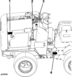
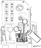
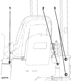
Opening the Hood
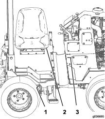
Pull the rubber hood latch (on each side of the hood) from the hood bracket (Figure 21) and open the hood.
Lubrication
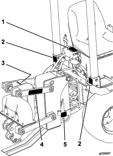
Greasing the Machine
| Maintenance Service Interval | Maintenance Procedure |
|---|---|
| Before each use or daily |
|
Grease Type: General-purpose grease.
Engine Maintenance
Engine Safety
-
Shut off the engine before checking the oil or adding oil to the crankcase.
-
Do not change the engine governor setting or overspeed the engine.
-
Keep your hands, feet, face, clothing, and other body parts away from the muffler and other hot surfaces.
Servicing the Air Cleaner
| Maintenance Service Interval | Maintenance Procedure |
|---|---|
| Before each use or daily |
|
| Every 250 hours |
|
| Every 500 hours |
|
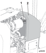
Servicing the Air-cleaner Cover and Body
Important: Service the air cleaner filter only when the service indicator is illuminated while the engine is running, after 1000 hours of operation or each year, whichever occurs first. Changing the air filter before it is necessary only increases the chance of dirt entering the engine when you remove the filter.
-
Lower the attachment, shut off the engine, and remove the key.
-
Check the air cleaner body for damage which could cause an air leak. Check the whole intake system for leaks, damage, or loose hose clamps. Replace or repair any damaged components.
-
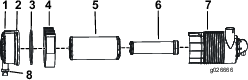
Release the latches on the air cleaner, and pull the air-cleaner housing off the air cleaner body (Figure 25).
Important: Do not remove the air filters.
-
Remove the dust cap and clean the inside with compressed air.
-
Install the dust cap ensuring that the dust valve on the bottom of the dust cap is pointing down.
-
Tighten the latch.
Replacing the Filters
If the air filter light illuminates, perform the following steps.
-
Gently slide the primary filter out of the air cleaner body (Figure 25).
Note: Avoid knocking the filter into the side of the body.
-
Inspect the new filter(s) for damage by looking into the filter while shining a bright light on the outside of the filter.
Note: Holes in the filter will appear as bright spots. Inspect the element for tears, an oily film, or damage to the rubber seal. If the filter is damaged, do not use it.
-
Clean the air filter housing with a moist cloth.
-
Install the new air filter element ensuring that the element is fully seated inside the air filter housing.
-
Install the dust cap ensuring that the dust valve on the bottom of the dust cap is pointing down.
-
Tighten the latch.
Servicing the Safety Filter
Replace the safety filter, never clean it.
Important: Never attempt to clean the safety filter. If the safety filter is dirty, then the primary filter is damaged. Replace both filters.
Servicing the Engine Oil
| Maintenance Service Interval | Maintenance Procedure |
|---|---|
| After the first 50 hours |
|
| Before each use or daily |
|
| Every 250 hours |
|
| Yearly or before storage |
|
Note: Change oil and oil filter more frequently when operating conditions are extremely dusty or sandy.
The engine is shipped with oil in the crankcase; however, the oil level must be checked before and after the engine is first started.
The crankcase capacity is approximately 5.2 L (5.5 US quarts) with the filter.
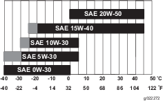
Use high-quality engine oil that meets the following specifications:
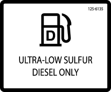
Oil Type: Detergent diesel engine oil (API service CJ-4 or higher)
Important: Using non CJ-4 or higher oil will cause DPF plugging and damage the engine.
Crankcase Capacity: w/filter, 5.2 L (5.5 US qt)
Viscosity: See Figure 26.
Checking the Engine-Oil Level
The engine is shipped with oil in the crankcase; however, the oil level must be checked before and after the engine is first started.
The best time to check the engine oil is when the engine is cool before it has been started for the day. If it has already been run, allow the oil to drain back down to the sump for at least 10 minutes before checking. If the oil level is at or below the add mark on the dipstick, add oil to bring the oil level to the Full mark. Do not overfill. If the oil level is between the Full and Add marks, no oil addition is required.
-
Park the machine on a level surface, lower any attachments, shut off the engine, and remove the key.
-
Unlock the engine cover latches and open the engine cover.
-
Remove the dipstick, wipe it clean, install the dipstick into the tube, and pull it out again.
The oil level should be in the safe range (Figure 27).
-
If the oil is below the safe range, remove the fill cap (Figure 27) and add oil until the level reaches the Full mark. Do not overfill.
Note: When using different oil, drain all old oil from the crankcase before adding new oil.
-
Install the oil fill cap and dipstick.
-
Close the engine cover and secure it with the latches.
Changing the Engine Oil
-
Start the engine and let it run for 5 minutes. This warms the oil so it drains better.
-
Park the machine on level ground, lower any attachments, set the parking brake, shut off the engine, and remove the key.
Caution
Components will be hot if the machine has been running. If you touch hot components you may be burned.
Allow the machine to cool before performing maintenance or touching components under the hood.
-
Remove the filler cap and the drain plug (Figure 28).
-
When the oil has drained completely, install the drain plug.
Note: Dispose of the used oil at a certified recycling center.
-
Slowly pour approximately 80% of the specified amount of oil in through the valve cover.
-
Check the oil level; refer to Checking the Engine-Oil Level.
-
Slowly add additional oil to bring the level to the upper hole on the dipstick.
-
Replace the fill cap.
Changing the Oil Filter
-
Drain the oil from the engine; refer to Changing the Engine Oil.
-
Place a shallow pan or rag under the filter to catch the oil.
-
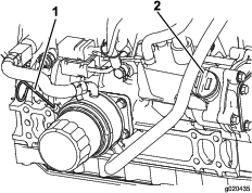
Remove the old filter (Figure 29) and wipe the surface of the gasket seal on the filter head.
-
Apply a thin layer of clean oil to the gasket seal of the new oil filter.
-
Apply a thin coat of the clean oil of the proper type through the center hole of the filter.
-
Allow 2 minutes for the oil to be absorbed by the filter material, then pour off any excess oil.
-
Install the replacement oil filter to the filter adapter by turning the oil filter clockwise until the rubber gasket contacts the filter adapter, then tighten the filter an additional 1/2 turn.
-
Fill the crankcase with the proper type of new oil; refer to Servicing the Engine Oil.
-
Start the engine and let it run for 30 seconds. Shut off the engine and let the machine cool.
-
Check the engine oil level; refer to Checking the Engine-Oil Level.
Servicing the Diesel Particulate Filter (DPF)
| Maintenance Service Interval | Maintenance Procedure |
|---|---|
| Every 3,000 hours |
|
Over time, ash accumulates in the DPF and a background regeneration is not sufficient to unclog the filter. When this occurs, the regeneration request and check engine lights illuminate on the control panel. At this time, the filter requires a stationary regeneration or needs to be replaced; contact your Authorized Service Dealer for more information.
When the ash accumulation reaches 50 g/L, the engine de-rates its power to 85%. At this time, remove the DPF and replace it with a clean DPF. If the DPF is not cleaned at the 50 g/L level, the engine continues to run at the de-rated 85% power level until the ash accumulation reaches 60 g/L. When the ash level reaches 60 g/L, the engine de-rates to 50% power. At this time, the DPF is fully plugged and needs to be removed and replaced with a clean DPF; contact your Authorized Service Dealer for more information.
Fuel System Maintenance
Danger
Under certain conditions, diesel fuel and fuel vapors are highly flammable and explosive. A fire or explosion from fuel can burn you and others and can cause property damage.
-
Use a funnel and fill the fuel tank outdoors, in an open area, when the engine is off and is cold. Wipe up any fuel that spills.
-
Do not fill the fuel tank completely full. Add fuel to the fuel tank until the level is 25 mm (1 inch) below the bottom of the filler neck. This empty space in the tank allows the fuel to expand.
-
Never smoke when handling fuel, and stay away from an open flame or where fuel fumes may be ignited by a spark.
-
Store fuel in a clean, safety-approved container and keep the cap in place.
Checking the Fuel Lines and Connections
| Maintenance Service Interval | Maintenance Procedure |
|---|---|
| Every 400 hours |
|
| Every 2,000 hours |
|
Inspect the fuel lines and connections for deterioration, damage, or loose connections. Tighten any loose connections and contact your Authorized Service Dealer for assistance in fixing damaged fuel lines.
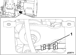
Draining the Fuel Filter/Water Separator
| Maintenance Service Interval | Maintenance Procedure |
|---|---|
| Before each use or daily |
|
| Every 50 hours |
|
-
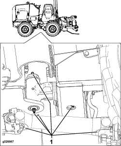
Locate the fuel filter on the right side of the engine and place a clean container under it.
-
Loosen the drain valve on the bottom of the filter canister and allow the water to drain.
-
When finished, tighten the drain valve.
Replacing the Fuel Filter Canister
| Maintenance Service Interval | Maintenance Procedure |
|---|---|
| Every 500 hours |
|
-
Clean the filter head and the outside of the fuel filter.
-
Turn the filter counterclockwise and remove the filter from the filter head.
-
Lubricate the gasket on the new filter canister with clean oil.
-
Install the filter canister by hand until the gasket contacts the filter head, then rotate it an additional 1/2 turn.
-
Start the engine and check for leaks.
Draining the Fuel Tank
| Maintenance Service Interval | Maintenance Procedure |
|---|---|
| Every 250 hours |
|
| Yearly or before storage |
|
Have an Authorized Service Dealer drain and clean the fuel tank.
Electrical System Maintenance
Electrical System Safety
-
Disconnect the battery before repairing the machine. Disconnect the negative terminal first and the positive last. Connect the positive terminal first and the negative last.
-
Charge the battery in an open, well-ventilated area, away from sparks and flames. Unplug the charger before connecting or disconnecting the battery. Wear protective clothing and use insulated tools.
-
Battery acid is poisonous and can cause burns. Avoid contact with skin, eyes, and clothing. Protect your face, eyes, and clothing when working with a battery.
-
Battery gases can explode. Keep cigarettes, sparks, and flames away from the battery.
Servicing the Battery
| Maintenance Service Interval | Maintenance Procedure |
|---|---|
| Every 100 hours |
|
| Every 250 hours |
|
Warning
Battery posts, terminals, and related accessories contain lead and lead compounds, chemicals known to the State of California to cause cancer and reproductive harm. Wash hands after handling.
Important: The following procedures apply when servicing a (dry) battery that has replaced the original battery. The original (wet) battery does not require service.
Always keep the battery clean and fully charged. Use a paper towel to clean the battery case. If the battery terminals are corroded, clean them with a solution of 4 parts water and 1 part baking soda. Apply a light coating of grease to the battery terminals to reduce corrosion.
Voltage: 12 V, 1,000 cold-cranking A
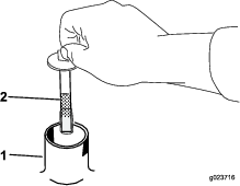
Charging the Battery
Warning
Charging the battery produces gasses that can explode.
Never smoke near the battery and keep sparks and flames away from battery.
Important: Always keep the battery fully charged (1.265 specific gravity). This is especially important to prevent battery damage when the temperature is below 0°C (32°F).
-
Charge the battery for 10 to 15 minutes at 25 to 30 A or 30 minutes at 4 to 6 A (Figure 30).
Note: Do not overcharge the battery.
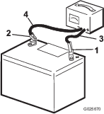
-
When the battery is fully charged, unplug the charger from the electrical outlet, then disconnect the charger leads from the battery posts (Figure 30).
-
Replace the battery cover.
Drive System Maintenance
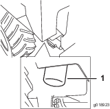
Servicing the Tires
Checking the Tires and Lug Nuts
| Maintenance Service Interval | Maintenance Procedure |
|---|---|
| Before each use or daily |
|
-
Do not exceed the rated tire pressure. To ensure long tire life and safe handling, check tire pressure daily, refer to Checking the Tire Pressure.
-
Inspect tires for cuts, slashes, or bulges. Tires with defects need to be replaced or repaired for proper handling and safety.
-
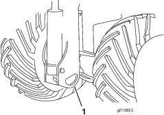
Check daily to ensure that all lug nuts are tight. Torque the lug nuts to 81-95 N∙m (60-70 ft-lb).

Checking the Tire Pressure
Maintain the air pressure in the tires as specified. Check the tires when they are cold to get the most accurate reading.
| Tire Size | Ply Rating | Pressure | |
|---|---|---|---|
| kPa | psi | ||
| 23 x 10.5 x 12 | 4 | 138 | 20 |
| 26 x 12 x 12 | 8 | 207 | 30 |
Note: Use a lower tire pressure when operating in sandy soil conditions to provide better traction in the loose soil.
Servicing the Transmission and Axles
Transmission oil specification: SAE 80W140 API classification level GL5
Transmission oil capacity: approximately 0.47 L (0.5 US qt)
Axle oil specification: SAE 80W140 API classification level GL5
Front axle oil capacity: approximately 2.4 L (2.5 US qt)
Rear axle oil capacity: approximately 2.4 L (2.5 US qt)
Toro Premium Gear Oil is available from an Authorized Service Dealer. See the parts catalog for part numbers.
Checking the Transmission Oil
| Maintenance Service Interval | Maintenance Procedure |
|---|---|
| Every 250 hours |
|
-
Park the machine on a level surface, lower any attachments, and shut off the engine.
-
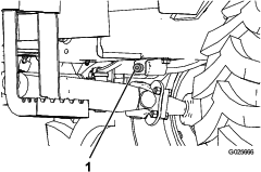
Clean the area around the fill plug with a cleaning solvent (Figure 32).

-
Remove the fill plug.
-
Check the oil level.
Note: The level should be even with the bottom of the fill plug
-
If the oil level is below the bottom of the fill plug hole, add oil to raise the level up to the bottom of the fill plug hole.
-
Install the fill plug.
Changing the Transmission Oil
| Maintenance Service Interval | Maintenance Procedure |
|---|---|
| Every 1,000 hours |
|
-
Park the machine on a level surface, lower any attachments, and shut off the engine.
-
Clean the area around the fill plug with a cleaning solvent (Figure 33).
-
Remove the fill and drain plug.
-
Drain the transmission oil into a container.
-
Insert the drain plug.
-
Fill the transmission until the oil level is even with the bottom of the fill-plug hole.
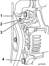
Checking the Axle Oil Levels
| Maintenance Service Interval | Maintenance Procedure |
|---|---|
| Every 100 hours |
|
-
Park the machine on a level surface, lower any attachments, and shut off the engine.
-
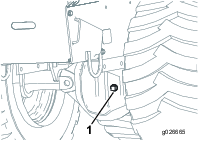
Remove the fill plug from 1 of the axle differentials (Figure 34).
-
Check the oil level.
Note: The oil level should be even with the bottom of the fill plug hole.
-
Add oil to raise the oil level up to the bottom of the fill plug hole.
-
Install the fill plug.
-
Repeat for the other differential.
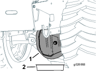
Changing the Axle Oil
-
Place a drain pan under the pinion housing of the axle.
-
Park the machine on a level surface, lower any attachments, and shut off the engine.
-
Remove the bolts securing the cover, and remove the cover and gasket.
-
Clean the surfaces and install a new gasket.
-
Install the cover and drain plug.
-
Remove the fill plug.
-
Fill with differential oil until the oil is level with the bottom of the fill plug hole.
-
Install the fill plug.
-
Repeat the procedure for the other differential.
Cooling System Maintenance
Cooling System Safety
-
Swallowing engine coolant can cause poisoning; keep out of reach from children and pets.
-
Discharge of hot, pressurized coolant or touching a hot radiator and surrounding parts can cause severe burns.
-
Always allow the engine to cool at least 15 minutes before removing the radiator cap.
-
Use a rag when opening the radiator cap, and open the cap slowly to allow steam to escape.
-
Servicing the Cooling System
| Maintenance Service Interval | Maintenance Procedure |
|---|---|
| Before each use or daily |
|
| Every 100 hours |
|
| Every 250 hours |
|
| Every 1,000 hours |
|
Coolant specification: a mixture of 50% ethylene glycol and 50% water
Engine and Radiator coolant capacity: 10.2 L (10.8 qt)
Danger
If the engine has been running, the pressurized, hot coolant can escape and cause severe burns.
-
Do not remove the radiator cap when the engine is hot. Always allow the engine to cool at least 15 minutes or until the radiator cap is cool enough to touch without burning your hand before removing the radiator cap.
-
Do not touch radiator and surrounding parts that are hot.
-
Use a rag when opening the radiator cap, and open the cap slowly to allow steam to escape.
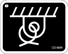
Danger
Rotating shaft and fan can cause personal injury.
-
Do not operate the machine without the covers in place.
-
Keep fingers, hands and clothing clear of rotating fan and drive shaft.
-
Shut off the engine and remove the ignition key before performing maintenance.
Caution
Swallowing engine coolant can cause poisoning.
-
Do not swallow engine coolant.
-
Keep out of reach from children and pets.
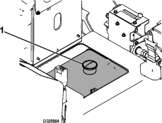
Checking the Engine Coolant Level
Check level of coolant at the beginning of each day. Capacity of the system is 8.5 L (9 qt).
-
Carefully remove the radiator cap.
Caution
If the engine has been running, the pressurized, hot coolant can escape and cause burns.
-
Do not open the radiator cap when the engine is running.
-
Use a rag when opening the radiator cap, and open the cap slowly to allow steam to escape.
-
-
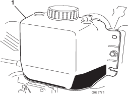
Check the coolant level in the radiator.
Note: The radiator should be filled to the top of the filler neck and the expansion tank filled to the Full mark (Figure 36).
-
If the coolant is low, add a 50/50 mixture of water and ethylene glycol anti freeze.
Note: Do not use water only or alcohol/methanol base coolants.
-
Install the radiator cap and expansion tank cap.
Changing the Engine Coolant
Have an Authorized Service Dealer change the engine coolant yearly.
If you need to add engine coolant, refer to Checking the Engine Coolant Level.
Belt Maintenance
Checking the Alternator Drive Belt Tension
| Maintenance Service Interval | Maintenance Procedure |
|---|---|
| Every 1,000 hours |
|
-
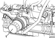
Push the drive belt with your thumb in the area shown to check the tension (Figure 37).
Note: The deflection should be between 7 to 10 mm (1/4 to 3/8 inch) under load of 98 N-m (22 ft-lb). If the deflection is less than 7 mm (1/4 inch) or more than 10 mm (3/8 inch), adjust the tension.
-
Loosen the pivot and adjusting bolts.
-
Pull the alternator away from the engine to increase belt tension or toward the engine to decrease belt tension, then tighten the adjusting bolts.
-
Check the belt tension. If the tension is correct, tighten the pivot bolts.
Replacing the Drive Belt
| Maintenance Service Interval | Maintenance Procedure |
|---|---|
| Every 4,000 hours |
|
-
Loosen the pivot bolts, the adjusting bolt, and move the alternator toward the engine to loosen the belt tension.
-
Remove the drive belt and install the new drive belt.
-
Adjust the belt tension to between 5 to 8 mm (3/16 to 5/16 inch) under load of 98 N-m (22 ft-lb).
-
Run the engine for 5 minutes and check the tension; the tension should be between 7 to 10 mm (1/4 to 3/8 inch) under load of 98 N-m (22 ft-lb).
Controls System Maintenance
The factory adjusts the controls before shipping the machine However, after many hours of use, you may need to adjust the controls.
Important: To adjust the controls properly, complete each procedure in the order listed.
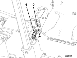
Checking the Parking Brake
Move the parking brake lever to the On position. If there is little or no resistance, complete the following procedure:
-
Park the machine on a flat surface, lower any attachments, shut off the engine, and remove the key.
-
Put the parking brake in the Off position.
-
Rotate the handle of the parking brake lever 2 or 3 times clockwise.
-
Apply the parking brake.
-
If there was resistance, the adjustment is correct.
-
If there was little or no resistance, see an Authorized Service Dealer.
-
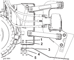
Adjusting the Traction Drive for Neutral
When positioned on a level surface, the machine must not creep when the traction lever is released. If it does creep, adjust as follows:
-
Park the machine on a level surface, shut off the engine, and lower the cutting unit to the floor.
-
Block the tires.
-
Loosen the jam nuts on each end of the rod.
-
Adjust the middle nut depending on which way the machine is creeping:
-
If the machine is creeping forward, turn the middle nut counter clockwise.
-
If the machine is creeping backward, turn the middle nut clockwise.
-
-
Tighten the jam nuts on each end of the rod.
-
Test the machine to see if further adjustment is needed.
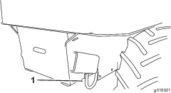
Cleaning the Directional Controls Linkage Assembly
| Maintenance Service Interval | Maintenance Procedure |
|---|---|
| Monthly |
|
Spray the direction controls linkage assembly with compressed air as shown in Figure 39.
Hydraulic System Maintenance
Hydraulic System Safety
-
Seek immediate medical attention if fluid is injected into skin. Injected fluid must be surgically removed within a few hours by a doctor.
-
Ensure that all hydraulic-fluid hoses and lines are in good condition and all hydraulic connections and fittings are tight before applying pressure to the hydraulic system.
-
Keep your body and hands away from pinhole leaks or nozzles that eject high-pressure hydraulic fluid.
-
Use cardboard or paper to find hydraulic leaks.
-
Safely relieve all pressure in the hydraulic system before performing any work on the hydraulic system.
Servicing the Hydraulic System
Hydraulic fluid reservoir capacity: 25.8 L (6.8 US gallons)
Use only one of the following fluids in the hydraulic system:
Toro Premium All Season Hydraulic Fluid (Available in 5-gallon pails or 55-gallon drums. See Parts Catalog or an Authorized Service Dealer for part numbers.)
Alternate fluids: If the Toro fluid is not available, other fluids may be used provided they meet all the following material properties and industry specifications. We do not recommend the use of synthetic fluid. Consult with your lubricant distributor to identify a satisfactory product.
Note: Toro will not assume responsibility for damage caused by improper substitutions, so use only products from reputable manufacturers who will stand behind their recommendation.
| Material Properties: | ||
| Viscosity, ASTM D445 | St @ 40° C 44 to 48 | |
| St @ 100° C 7.9 to 8.5 | ||
| Viscosity Index ASTM D2270 | 140 to 160 | |
| Pour Point, ASTM D97 | -34° F to -49° F | |
| FZG, Fail stage | 11 or better | |
| Water content (new fluid) | 500 ppm (maximum) | |
| Industry Specifications: | Vickers I-286-S (Quality Level), Vickers M-2950-S (Quality Level), Denison HF-0 | |
Replacing the Hydraulic Filter
| Maintenance Service Interval | Maintenance Procedure |
|---|---|
| After the first 25 hours |
|
| Every 1,000 hours |
|
Important: Do not substitute an automotive oil filter or severe hydraulic system damage may result.
-
Position the machine on a level surface.
-
Lower any attachments, shut off the engine, and remove the key.
-
Place a pan under the hydraulic filter to catch the fluid.
-
Turn the hydraulic-fluid filter counterclockwise, remove and discard the filter (Figure 40).
-
Apply a thin coat hydraulic fluid to the rubber gasket on the replacement filter.
-
Fill the hydraulic filter with clean hydraulic fluid.
-
Install the replacement hydraulic filter onto the filter head. Tighten it clockwise until the filter contacts the filter head, then tighten the filter an additional 3/4 turn.
-
Clean up any spilled fluid.
-
Start the engine and let it run for about 2 minutes to purge any air from the system.
-
Shut off the engine and check for leaks.
Checking the Hydraulic-Fluid Level
| Maintenance Service Interval | Maintenance Procedure |
|---|---|
| Before each use or daily |
|
Important: Always use the correct hydraulic fluid. Unspecified fluids will damage the hydraulic system.
-
Park the machine on a level surface, and lower any attachments.
-
Shut off the engine, remove the key, and allow the engine to cool.
-
Open the hood.
-
Clean the area around the filler neck of the hydraulic tank.
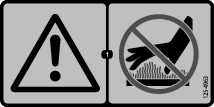
Caution
During regeneration, the diesel particulate filter becomes extremely hot and can cause serious burns.
Keep your body and hands away from the engine during regeneration.
-
Remove the cap from the filler neck and check the fluid level on the dipstick (Figure 41).
The fluid level should be between the marks on the dipstick.
-
If the level is low, add enough fluid to raise it to the proper level.
-
Install the cap on the filler neck.
-
Close the hood.
Changing the Hydraulic Fluid
| Maintenance Service Interval | Maintenance Procedure |
|---|---|
| After the first 250 hours |
|
| Every 1,000 hours |
|
-
Position the machine on a level surface.
-
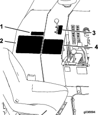
Remove the upper left panel of the console (Figure 42).
-
Place a large drain pan (capable of holding 57 liters (15 US gallons) on the ground under the hydraulic tank.
-
Remove the hydraulic tank cap and use a pump to empty the hydraulic tank.
-
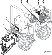
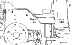
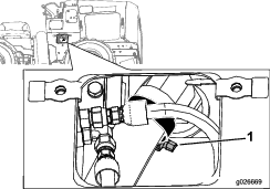
Remove the lower right side cover plate and loosen the hose clamp holding the suction hose to the hydraulic tank (Figure 43).
-
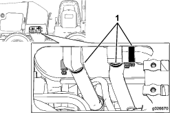
Remove the left side cover plate and loosen the 3 hose clamps under the hydraulic tank (Figure 44).
-
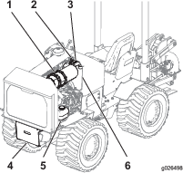
Disconnect the electrical lead to the oil temperature sending unit at the bottom of the reservoir.
-
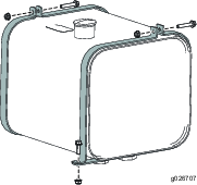
Loosen the hydraulic tank straps and remove the hydraulic tank from the machine (Figure 45).
-
Flush the reservoir with cleaning solvent.
-
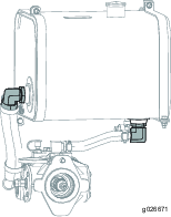
Remove the elbow adapters and remove and clean the filter screens with compressed air (Figure 46).
-
Put thread sealant on the threads of the suction screen and install the screen, elbow, hose, and clamp.
-
Connect the electrical lead to the oil temperature sending unit at the bottom of the reservoir.
-
Install the hose to the tank and secure the clamps.
-
Install the hydraulic tank assembly.
-
Fill the hydraulic tank with approximately 25.8 L (6.8 US gallons) of Toro premium all season hydraulic fluid ISO VG 46.
Dispose of the used oil at a certified recycling center.
-
Install the dipstick cap.
-
Start the engine and let it run for a few minutes.
-
Shut off the engine.
-
Check the hydraulic fluid level and top it off if necessary; refer to Checking the Hydraulic-Fluid Level.
Checking the Hydraulic Lines
| Maintenance Service Interval | Maintenance Procedure |
|---|---|
| Every 100 hours |
|
| Every 1,500 hours |
|
Check the hydraulic lines for leaks, loose fittings, kinked lines, loose mounting supports, wear, weather, and chemical deterioration. Make necessary repairs before operating.
ROPS Maintenance
Checking and Servicing the ROPS
Checking and Caring for the Seat Belt
Before you operate the machine, always ensure that the ROPS and the seat belt are properly installed and in good working order.
-
Check the seat belt for damage, and replace all parts that are damaged.
-
Ensure that the mounting bolts for the seat belts are tight.
-
Keep the seat belts clean using only soap and water.
Note: Do not immerse the seat belts in bleach or dye, because this weakens the belt material.
Checking and Maintaining the ROPS
| Maintenance Service Interval | Maintenance Procedure |
|---|---|
| Every 500 hours |
|
Important: If any part of the ROPS system is damaged, replace it before you operate the machine.
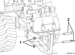
-
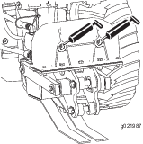
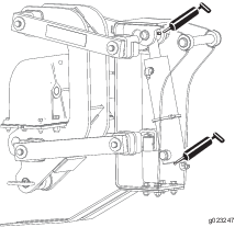
Check that the 4 bolts that secure the ROPS bar to the chassis of the machine are torqued to 203 to 223 N∙m (150 to 165 ft-lb); refer to Figure 47.
-
Check that the bolts and nuts that attach the seat-belt retractor and buckle to the seat are torqued to 104 to 115 N∙m (77 to 85 ft-lb); refer to Figure 47.
Note: Replace any parts that are worn or damaged.
-
Inspect the ROPS for cracks, rust, or holes in the ROPS and component parts.
Note: Age, weather, and accidents cause damage to the ROPS and ROPS parts. If you have any doubts about the ROPS system, contact an Authorized Service Dealer.
Replacing a Damaged ROPS System
If the ROPS system has been damaged in an accident, such as a rollover or hitting an overhead object during transport, replace any damaged ROPS components to restore the ROPS system to its original level of protection.
After an accident, check the following items for damage:
-
The ROPS bar
-
Operator seat
-
Seat belt mounting
-
Seat belt
Before you operate the machine, replace all damaged ROPS components; contact an Authorized Service Dealer.
Important: Do not try to weld or straighten a damaged ROPS bar.
Cleaning
Removing Debris from the Machine
| Maintenance Service Interval | Maintenance Procedure |
|---|---|
| Before each use or daily |
|
Important: Operating the engine with blocked screens and/or cooling shrouds removed, will result in engine damage from overheating.
-
Park the machine on a level surface, lower any attachments, and shut off the engine.
-
Remove the key and allow the engine to cool.
-
Open the hood.
-
Clean any debris from the front and side screens.
-
Wipe away any debris from the air cleaner.
-
Clean any debris build-up on the engine and in the oil cooler fins with compressed air.
Important: It is preferable to blow dirt out, rather than washing it out. If water is used, keep it away from electrical items and hydraulic valves. Do not use a high-pressure washer. High-pressure washing can damage the electrical system and hydraulic valves or deplete grease.
-
Clean debris from the hood opening, muffler, and heat shields.
-
Close the hood.
Cleaning the Chassis
| Maintenance Service Interval | Maintenance Procedure |
|---|---|
| Every 100 hours |
|
Over time, the chassis under the engine collects dirt and debris that must be removed. Using a flashlight, open the hood and inspect the area under the engine on a regular basis. When the debris is 2 to 5 cm (1 to 2 inches) deep, have an Authorized Service Dealer remove the rear of the machine, fuel tank, and battery and flush the chassis clean.