
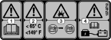
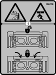
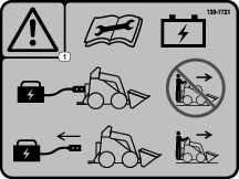
 , which means Caution, Warning,
or Danger—personal safety instruction. Failure to comply with
these instructions may result in personal injury or death.
, which means Caution, Warning,
or Danger—personal safety instruction. Failure to comply with
these instructions may result in personal injury or death.


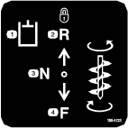


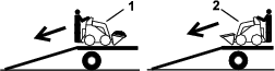
 , when used with Eco mode,
slows the motor speed (in rpm) to reduce energy consumption when using
attachments. Bucket Mode
, when used with Eco mode,
slows the motor speed (in rpm) to reduce energy consumption when using
attachments. Bucket Mode  maintains the motor speed.
Maintenance
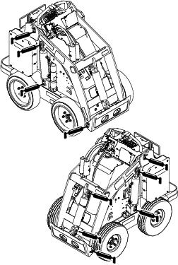
Note: Determine the left and right sides of the machine from the normal operating position.
Caution
If you leave the key in the switch, someone could accidently start the machine and seriously injure you or other bystanders.
Remove the key from the switch and disconnect the power before you perform any maintenance.
Maintenance Safety
-
Park the machine on a level surface, disengage the auxiliary hydraulics, lower the attachment, engage the parking brake, shut off the machine, and remove the key. Wait for all movement to stop and allow the machine to cool before adjusting, cleaning, storing, or repairing it.
-
Do not allow untrained personnel to service the machine.
-
Use jack stands to support the components when required.
-
Carefully release pressure from components with stored energy; refer to Relieving Hydraulic Pressure.
-
Disconnect the battery before making any repairs; refer to Disconnecting the Main Power.
-
Keep your hands and feet away from the moving parts. If possible, do not make adjustments with the machine running.
-
Keep all parts in good working condition and all hardware tightened. Replace all worn or damaged decals.
-
Do not tamper with the safety devices.
-
Use only Toro-approved attachments. Attachments can change the stability and the operating characteristics of the machine. You may void the warranty if you use the machine with unapproved attachments.
-
Use only genuine Toro replacement parts.
-
If any maintenance or repair requires the loader arms to be in the raised position, secure the arms in the raised position with the hydraulic-cylinder lock(s).
Recommended Maintenance Schedule(s)
| Maintenance Service Interval | Maintenance Procedure |
|---|---|
| After the first 8 hours |
|
| Before each use or daily |
|
| Every 25 hours |
|
| Every 100 hours |
|
| Every 400 hours |
|
| Yearly |
|
| Yearly or before storage |
|
Pre-Maintenance Procedures
Using the Cylinder Locks
Warning
The loader arms may lower when in the raised position, crushing anyone under them.
Install the cylinder lock(s) before performing maintenance that requires raised loader arms.
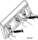
Installing the Cylinder Locks
-
Remove the attachment.
-
Raise the loader arms to the fully raised position.
-
Shut off the machine and remove the key.
-
Position a cylinder lock over each lift-cylinder rod (Figure 25).
-
Secure each cylinder lock with a clevis pin and cotter pin (Figure 25).
-
Slowly lower the loader arms until the cylinder locks contact the cylinder bodies and rod ends.
Removing and Storing the Cylinder Locks
Important: Remove the cylinder locks from the rods and fully secure them in the storage position before operating the machine.
-
Start the machine.
-
Raise the loader arms to the fully raised position.
-
Shut off the machine and remove the key.
-
Remove the clevis pin and cotter pin securing each cylinder lock.
-
Remove the cylinder locks.
-
Lower the loader arms.
-
Install the cylinder locks over the hydraulic hoses and secure them with the clevis pins and cotter pins (Figure 26).
Accessing Internal Components
Warning
Opening or removing covers, hoods, and screens while the machine is running could allow you to contact moving parts, seriously injuring you.
Before opening any of the covers, hoods, and screens, shut off the machine, remove the key from the key switch, and allow the machine to cool.
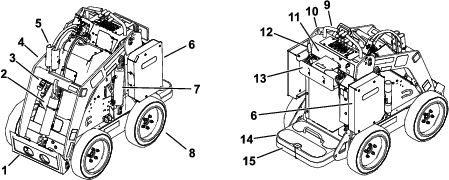
Removing the Hood
Note: If you need to access the main-power connectors or fuse but cannot safely raise the loader arms to remove the hood, refer to Removing the Front Cover for access.
-
Park the machine on a level surface.
-
Raise the loader arms and install the cylinder locks.
Note: If you cannot raise the loader arms using the machine power, pull the loader-arm lever rearward and use a hoist to lift the loader arms.
-
Shut off the machine and remove the key.
-
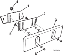
Loosen the 4 nuts securing the hood (Figure 27).
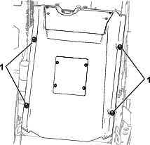
-
Pull the hood off the machine.
Removing the Front Cover
Important: Remove the front cover to access the main-power connectors and fuse only when you are unable to safely raise the loader arms to remove the hood.
-
Park the machine on a level surface, lower the loader arms, and engage the parking brake.
-
Shut off the machine and remove the key.
-
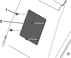
Remove the 4 bolts securing the front cover and remove the cover (Figure 28).
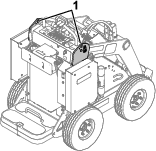
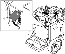
Disconnecting the Main Power
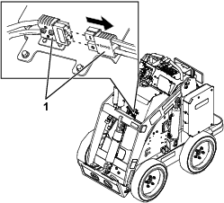
Before you service the machine, disconnect the machine from the power supply by separating the main-power connectors (Figure 29).
-
Park the machine on a level surface.
-
Raise the loader arms and install the cylinder locks.
-
Shut off the machine and remove the key.
-
Remove the hood; refer to Removing the Hood.
-
Separate the 2 power connectors (Figure 29).
-
Make any repairs.
-
Plug the connectors together before operating the machine.
Caution
If you do not disconnect the power to the machine, someone could accidentally turn on the machine, causing serious bodily injury.
Always separate the connectors before working on the machine.
Lubrication
Greasing the Machine
| Maintenance Service Interval | Maintenance Procedure |
|---|---|
| Before each use or daily |
|
Grease Type: General-purpose grease
-
Park the machine on a level surface, lower the loader arms, and engage the parking brake.
-
Shut off the machine and remove the key.
-
Clean the grease fittings with a rag.
-
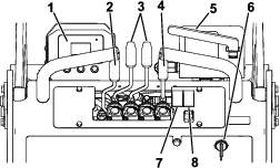
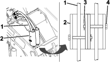
Connect a grease gun to each fitting (Figure 30 and Figure 31).
-
Pump grease into the fittings until grease begins to ooze out of the bearings (approximately 3 pumps).
-
Wipe up any excess grease.
Electrical System Maintenance
Electrical System Safety
-
Disconnect the main-power connectors before repairing the machine.
-
Charge the battery in an open, well-ventilated area, away from sparks and flames. Unplug the charger before connecting or disconnecting the battery. Wear protective clothing and use insulated tools.
Disconnecting or Connecting Power to the Machine
The main-power connectors provide power from the batteries to the machine. Disconnect the power by separating the connectors; connect the power by installing the connectors together. Refer to Disconnecting the Main Power.
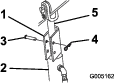
Replacing the Static Strap
| Maintenance Service Interval | Maintenance Procedure |
|---|---|
| Before each use or daily |
|
-
Park the machine on a level surface, lower the loader arms, and engage the parking brake.
-
Shut off the machine and remove the key.
-
Under the platform, replace the static strap as shown in Figure 32.

Servicing the Batteries
Note: The machine is equipped with 7 lithium-ion batteries.
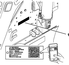
If you attempt to open the main compartment of a battery, you will void your warranty. If a battery requires service, contact your Authorized Service Dealer for assistance.
Dispose of or recycle lithium-ion batteries in accordance with local and federal regulations.
Maintaining the Battery Charger
Important: All electrical repairs should be performed by an Authorized Service Dealer only.
The operator can perform very little maintenance other than protecting the charger from damage and weather.
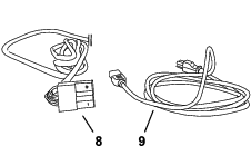
Maintaining the Battery-Charger Cords
-
Clean the cords with a slightly damp cloth after each use.
-
Coil the cords when not in use.
-
Periodically examine the cords for damage, and replace them when necessary with Toro-approved parts.
Cleaning the Battery-Charger Case
Clean the case with a slightly damp cloth after each use.
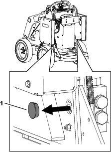
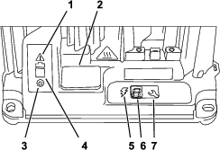
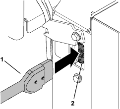
Servicing the Fuse
-
Park the machine on a level surface.
-
Raise the loader arms and install the cylinder locks.
-
Shut off the machine and remove the key.
-
Remove the hood; refer to Removing the Hood.
-
Disconnect the main power to the machine; refer to Disconnecting the Main Power.
-
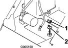
Locate the fuse and replace it (Figure 33).
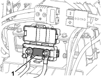
-
Torque the nuts to 12 to 18 N∙m (9 to 13 ft-lb).
-
Connect the main-power connectors.
-
Install the front cover.
Drive System Maintenance
Checking the Tire Treads
| Maintenance Service Interval | Maintenance Procedure |
|---|---|
| Before each use or daily |
|
Check the tire treads for wear. Replace the tires when the treads are worn and shallow.
Checking the Wheel-Lug Nuts
| Maintenance Service Interval | Maintenance Procedure |
|---|---|
| After the first 8 hours |
|
| Every 100 hours |
|
Check and torque the wheel lug nuts to 68 N∙m (50 ft-lb).
Brake Maintenance
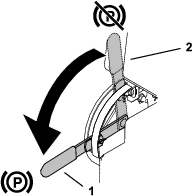
Testing the Parking Brake
| Maintenance Service Interval | Maintenance Procedure |
|---|---|
| Before each use or daily |
|
-
Engage the parking-brake; refer to Parking-Brake Lever.
-
Start the machine.
-
Slowly attempt to drive the machine forward or rearward.
Note: The machine may move some before the parking brake locks in place.
-
If the machine moves without the parking brake locking in place, contact your Authorized Service Dealer for service.
Hydraulic System Maintenance
Hydraulic System Safety
-
Seek immediate medical attention if fluid is injected into skin. Injected fluid must be surgically removed within a few hours by a doctor.
-
Ensure that all hydraulic-fluid hoses and lines are in good condition and all hydraulic connections and fittings are tight before applying pressure to the hydraulic system.
-
Keep your body and hands away from pinhole leaks or nozzles that eject high-pressure hydraulic fluid.
-
Use cardboard or paper to find hydraulic leaks.
-
Safely relieve all pressure in the hydraulic system before performing any work on the hydraulic system.
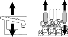
Relieving Hydraulic Pressure
To relieve hydraulic pressure while the machine is on, disengage the auxiliary hydraulics and fully lower the loader arms.
To relieve the pressure while the machine is off, move the auxiliary-hydraulics lever between the forward and reverse flow positions to relieve auxiliary hydraulic pressure, move the attachment-tilt lever forward and rearward, and move the loader-arm lever forward to lower the loader arms (Figure 34).
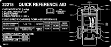
Hydraulic Fluid Specifications
| Maintenance Service Interval | Maintenance Procedure |
|---|---|
| Every 25 hours |
|
Hydraulic Tank Capacity: 56 L (14.8 US gallons)
Use only 1 of the following fluids in the hydraulic system:
-
Toro Premium Transmission/Hydraulic Tractor Fluid (refer to your Authorized Service Dealer for more information)
-
Toro PX Extended Life Hydraulic Fluid (refer to your Authorized Service Dealer for more information)
-
If either of the above Toro fluids are not available, you may use another Universal Tractor Hydraulic Fluid (UTHF), but they must be only conventional, petroleum-based products. The specifications must fall within the listed range for all the following material properties and the fluid should meet the listed industry standards. Check with your hydraulic fluid supplier to determine if the fluid meets these specifications.
Note: Toro will not assume responsibility for damage caused by improper substitutions, so use only products from reputable manufacturers who will stand behind their recommendations.
Material Properties Viscosity, ASTM D445 cSt at 40°C: 55 to 62 cSt at 100°C: 9.1 to 9.8 Viscosity index, ASTM D2270 140 to 152 Pour Point, ASTM D97 -43 to -37°C (-46 to -35°F) Industry Standards API GL-4, AGCO Powerfluid 821 XL, Ford New Holland FNHA-2-C-201.00, Kubota UDT, John Deere J20C, Vickers 35VQ25 and Volvo WB-101/BM Note: Many hydraulic fluids are almost colorless, making it difficult to spot leaks. A red dye additive for the hydraulic system fluid is available in 20 ml (0.67 fl oz) bottles. One bottle is sufficient for 15 to 22 L (4 to 6 US gallons) of hydraulic fluid. Order Part No. 44-2500 from your Authorized Service Dealer.
Checking the Hydraulic-Fluid Level
| Maintenance Service Interval | Maintenance Procedure |
|---|---|
| Every 25 hours |
|
Check the hydraulic-fluid level before the machine is first started and after every 25 operating hours.
Refer to Hydraulic Fluid Specifications.
Important: Always use the correct hydraulic fluid. Unspecified fluids will damage the hydraulic system.
-
Park the machine on a level surface, remove any attachment, engage the parking brake, raise the loader arms, and install the cylinder locks.
-
Shut off the machine, remove the key, and allow the machine to cool.
-
Remove the hood/front access cover.
-
Clean the area around the filler neck of the hydraulic tank (Figure 35).
-
Remove the filler-neck cap and check the fluid level on the dipstick (Figure 35).
The fluid level should be between the marks on the dipstick.
-
If the level is low, add enough fluid to raise it to the proper level.
-
Install the filler-neck cap.
-
Install the hood/front access cover.
-
Remove and store the cylinder locks and lower the loader arms.
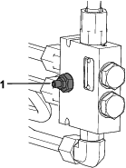
Replacing the Hydraulic Filter
| Maintenance Service Interval | Maintenance Procedure |
|---|---|
| After the first 8 hours |
|
| Every 400 hours |
|
Important: Do not substitute an automotive oil filter; otherwise, severe hydraulic system damage may result.
-
Park the machine on a level surface, remove any attachment, engage the parking brake, raise the loader arms, and install the cylinder locks.
-
Shut off the machine and remove the key.
-
Remove the hood.
-
Place a drain pan under the filter.
-
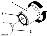
Remove the old filter (Figure 36) and wipe the surface of the filter adapter clean.
-
Apply a thin coat hydraulic fluid to the rubber gasket on the replacement filter (Figure 36).
-
Install the replacement hydraulic filter onto the filter adapter (Figure 36). Tighten it clockwise until the rubber gasket contacts the filter adapter, then tighten the filter an additional 1/2 turn.
-
Clean up any spilled fluid.
-
Start the machine and let it run for about 2 minutes to purge air from the system.
-
Shut off the machine and check for leaks.
-
Check the fluid level in the hydraulic tank; refer to Checking the Hydraulic-Fluid Level. Add fluid to raise the level to mark on dipstick. Do not overfill the tank.
-
Install the hood.
-
Remove and store the cylinder locks and lower the loader arms.
Changing the Hydraulic Fluid
| Maintenance Service Interval | Maintenance Procedure |
|---|---|
| Yearly |
|
-
Park the machine on a level surface, remove any attachment, engage the parking brake, raise the loader arms, and install the cylinder locks.
-
Shut off the machine and remove the key.
-
Remove the hood.
-
Place a large drain pan under the machine that can hold at least 61 L (16 US gallons).
-
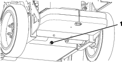
Remove the drain plug from the bottom of the hydraulic tank and allow the fluid to completely drain out (Figure 37).
-
Install the drain plug.
-
Fill the hydraulic tank with hydraulic fluid; refer to Hydraulic Fluid Specifications.
Note: Dispose of used fluid at a certified recycling center.
-
Install the hood.
-
Remove and store the cylinder locks and lower the loader arms.
Cleaning
Removing Debris
| Maintenance Service Interval | Maintenance Procedure |
|---|---|
| Before each use or daily |
|
-
Park the machine on a level surface, lower the loader arms, and engage the parking brake.
-
Shut off the machine and remove the key.
-
Clean any debris from the machine.
Important: Blow the dirt out rather than wash it out. If you use water, keep it away from electrical items and hydraulic valves.
-
Remove and store the cylinder locks and lower the loader arms.
Washing the Machine
When pressure washing the machine, do the following:
-
Wear appropriate personal protective equipment for the pressure washer.
-
Keep all guards in place on the machine.
-
Avoid spraying at electronic components.
-
Avoid spraying at edges of decals.
-
Spray the exterior of the machine only. Do not spray directly into openings in the machine.
-
Spray only the dirty parts of the machine.
-
Use a 40-degree or larger spray nozzle. 40-degree nozzles are usually white.
-
Keep the tip of the pressure washer at least 61 cm (2 ft) away from the surface being washed.
-
Use only pressure washers with pressure below 13790 kpa (2000 psi) and flow below 7.6 L (2 US gallons) per minute.
-
Replace damaged or peeling decals.
-
Grease all grease points after washing; refer to Greasing the Machine.