Maintenance
Recommended Maintenance Schedule(s)
| Maintenance Service Interval | Maintenance Procedure |
|---|---|
| After the first 8 hours |
|
| Before each use or daily |
|
| Every 50 hours |
|
| Every 100 hours |
|
| Every 250 hours |
|
| Every 500 hours |
|
| Before storage |
|
| Yearly |
|
Maintenance Safety
-
Before adjusting, cleaning, servicing, or leaving the machine, do the following:
-
Position the machine on a level surface.
-
Move the throttle switch to the low-idle position.
-
Disengage the PTO.
-
Ensure that the traction is in neutral.
-
Engage the parking brake.
-
Shut off the engine of the traction unit and remove the key.
-
Wait for all moving parts to stop.
-
Allow machine components to cool before performing maintenance.
-
-
Perform only those maintenance instructions described in this manual. If major repairs are ever needed or assistance is desired, contact an authorized Toro distributor.
-
Ensure that the machine is in safe operating condition by keeping nuts, bolts, and screws tight.
-
If possible, do not perform maintenance while the engine is running. Keep away from moving parts.
-
Do not check or adjust the chain tension when the traction unit engine is running.
-
Carefully release pressure from components with stored energy.
-
Support the machine with blocks or storage stands when working beneath it. Never rely on the hydraulic system to support the machine.
-
Check the tine mounting bolts daily to be sure that they are tightened to specification.
-
Ensure that all guards are installed and the hood is secured shut after maintaining or adjusting the machine.
-
To ensure safe, optimal performance of the machine, use only genuine Toro replacement parts. Replacement parts made by other manufacturers could be dangerous, and such use could void the product warranty.
Jacking the Machine
Caution
If the machine is not properly supported by blocks or jack stands, the machine may move or fall, which may result in personal injury.
-
Ensure that the machine is parked on a solid, level surface such as a concrete floor. Always chock the traction unit tires.
-
Prior to raising the machine, remove any attachments that may interfere with the safe and proper raising of the machine.
-
When changing attachments or performing other service, use correct blocks, hoists or jacks.
-
Use jack stands or solid wood blocks to support the raised machine.
Note: If available, use a hoist to lift the rear of the machine. Use the eyelets in the coring head bearing housings as hoist attachment points (Figure 26)
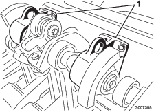
Greasing the Bearings and Bushings
| Maintenance Service Interval | Maintenance Procedure |
|---|---|
| Every 50 hours |
|
The main working bearings of the machine are sealed for life and require no maintenance or lubrication. This drastically reduces the maintenance required and eliminates the risk of grease or oil being dropped onto the turf.
There are grease fittings that must be lubricated with an SAE multi-purpose, high-temperature grease with high-pressure (EP) performance or SAE multi-purpose lithium-based grease.
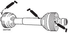
The lubrication points are:
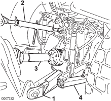
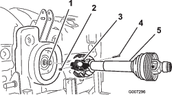
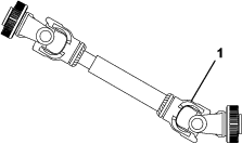
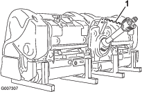
PTO driveshaft (3) (Figure 27)
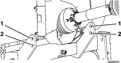
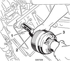
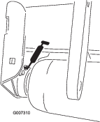
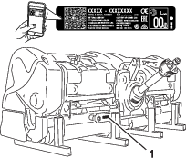
Roller bearings (ProCore 864: 2; ProCore 1298: 4) (Figure 28)
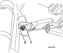
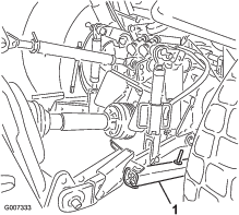
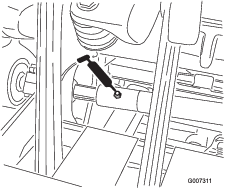
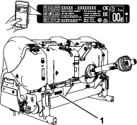
Driveshaft bearings (ProCore 864:1; ProCore 1298: 2) (Figure 29)
Important: Bearings rarely fail from defects in materials or workmanship. The most common reason for failure is moisture and contamination working its way past the protective seals. Bearings that are greased rely upon regular maintenance to purge harmful debris from the bearing area. Sealed bearings rely on an initial fill of special grease and a robust integral seal to keep contaminants and moisture out of the rolling elements.
The sealed bearings require no lubrication or short term maintenance. Use of sealed bearings minimizes routine service and reduces the potential turf damage from grease contamination. Inspect of bearing condition and seal integrity periodically to avoid downtime. Inspect the sealed bearings seasonally and replaced them if they are damaged or worn. Check that the bearings do not produce high heat, emit noise, vibrate excessively, or weep rust; the bearings should operate smoothly.
Due to the operating conditions these bearing/seal packages are subject to (i.e. sand, turf chemicals, water, impacts, etc.) they are considered normal wear items. Bearings that fail due to other than defects in materials or workmanship are typically not covered under warranty.
Note: Bearing life can be negatively affected by improper washing procedures. Do not wash the unit when it is still hot and avoid directing high-pressure or high-volume spray at the bearings.New bearings commonly purge some grease out of the seals on a new machine. This purged grease turns black in color due to collection of debris and not due to excessive heat. Wipe this excess grease from the seals after the initial 8 hours. The area around the seal lip may always appear wet. This is not detrimental to bearing life, but keeps the seal lip lubricated.Replace the coring head bearing every of 500 hours. A bearing service kit that covers the complete coring head is available from your distributor.
Checking the Gearbox Lubrication
| Maintenance Service Interval | Maintenance Procedure |
|---|---|
| Every 100 hours |
|
The gearbox is filled with 80W-90 gear oil or equivalent. Allow the gearbox to cool before checking the lubrication.
-
Clean debris from the fill plug and check the plug to avoid contamination.
-
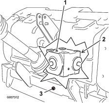
Remove the check plug from the gearbox (Figure 30).
-
Make sure that the oil level is up to the bottom of the check plug hole in gearbox (Figure 30).
-
If the oil level is low, remove the fill plug from the gearbox and add oil as required.
-
Install the plugs.
Changing the Gearbox Lubrication
| Maintenance Service Interval | Maintenance Procedure |
|---|---|
| After the first 8 hours |
|
| Every 250 hours |
|
The gearbox is filled with 80W-90 gear oil or equivalent.
-
Clean debris from the fill plug and the drain cap to avoid contamination (Figure 30).
-
Remove the fill plug to relieve air draw.
-
Position a drain pan under the drain tube and remove the drain cap.
Note: The high viscosity of cool oil extends the drain time (approximately 30 minutes).
-
After oil is completely drained, install the drain cap.
-
Fill the gearbox with 1650 ml (56 fl oz) of high quality 80W-90 gear lube.
-
Install the fill plug.
-
Check the oil level.
Checking the Coring Head Fastener Torque
| Maintenance Service Interval | Maintenance Procedure |
|---|---|
| After the first 8 hours |
|
| Every 250 hours |
|
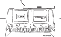
After the initial 8 hours of use, check the coring head fasteners to ensure that proper torque is maintained. Fastener torque requirements are listed on the reference service decal below and located on the coring head.

Inspecting the Belts
| Maintenance Service Interval | Maintenance Procedure |
|---|---|
| Yearly |
|
The drive belt(s) on the machine are durable. However, the normal exposure to UV radiation, ozone or incidental exposure to chemicals can deteriorate the rubber compounding over time and lead to premature wear or material loss (i.e. chunking).
Annual belt inspection is highly recommended for signs of wear, excessive cushion cracks, or large embedded debris with replacement when needed.
Adjusting the Belt Tension
| Maintenance Service Interval | Maintenance Procedure |
|---|---|
| Before each use or daily |
|
Make sure that the belt is properly tensioned to ensure correct operation of the machine and to prevent unnecessary wear.
-
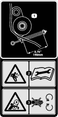
Check for proper belt tension by compressing idler spring to a length of 146 mm (5-3/4 inches); refer to Figure 32.
-
Adjust the belt tension as follows:
-
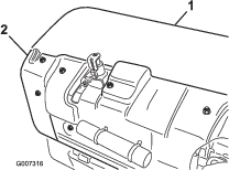
Remove the rear coring head cover (Figure 33).
-
Remove the pulley shield mounting bolts and remove the shield (Figure 33).
-
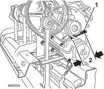
Loosen the locknut securing the spring retainer (Figure 34).
-
Adjust the spring retainer to attain required compressed spring length (Figure 34).
-
Tighten the locknut against the spring retainer to lock the adjustment.
-
Install the pulley shield and the coring head cover.
-
Replacing the Drive Belt
Note: You do not need to remove the outside stomper arm to replace the drive belt.
Removing the Belt
-
Remove the rear coring head cover (Figure 35).

-
Remove the pulley shield mounting bolts and remove the shield (Figure 35).
-
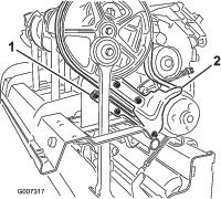
Remove the fasteners securing the dirt shield and the lower belt shield (Figure 36). Remove the dirt shield and the lower belt shield.
-
To release the idler spring tension, loosen the locknut securing the spring retainer (Figure 37) and rotate the spring retainer.
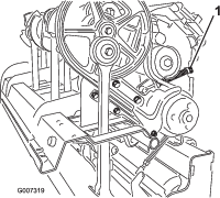
Caution
Springs are under tension, use caution when adjusting or removing.
-
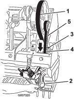
Loosen and remove the 2 locknuts and washers securing the rotalink damper for the #1 stomper arm (Figure 38).
-
Lower the rotalink damper from the coring head frame.
-
Route the drive belt down through the coring head frame and around the lower end of the #1 stomper arm (Figure 38).
Installing the Belt
-
Route the new drive belt around the lower end of the #1 stomper arm and up through the coring head frame.
-
Position the drive belt onto the crank pulley, under the idler assembly and over the drive pulley.
-
Raise the rotalink damper for the #1 stomper arm to coring head frame. Ensure that the damper spacers are installed in the same position as in removal.
-
Secure the rotalink damper to the coring head with the 2 washers and locknuts previously removed.
-
Install and adjust the belt idler pulley and adjust it to the appropriate tension.
-
Install the dirt shield and the lower belt shield. Adjust the lower shield to ensure clearance with the belt.
-
Install the pulley and the coring head covers.
Adjusting the Side Shield
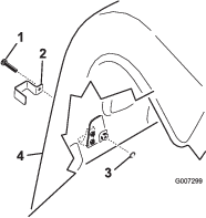
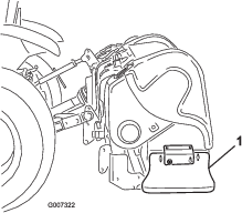
The coring head side shields should be adjusted so that the bottom rides between 25 to 38 mm (1 to 1-1/2 inches) from the turf while aerating.
-
Loosen the bolts and nuts securing the side shield to frame (Figure 39).
-
Adjust the shield up or down and tighten the nuts.
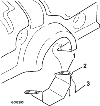
Replacing the Turf Guards
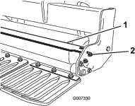
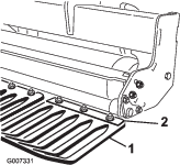
All turf guards (Figure 40) should be replaced if broken or worn to less than 1/4 inch thickness. Broken turf guards can catch and tear turf, creating undesirable damage.
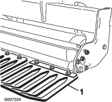
Coring Head Timing
The unitized coring head design of the machine provides industry-leading smooth operation while taking out the guesswork of timing.
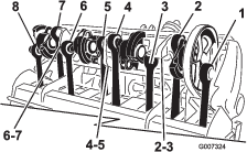
ProCore 864 (Figure 41)
Each pair of crank arms joined through a bearing housing are timed 180 degrees apart (i.e. arm positions 1-2, 3-4, 5-6, 7-8). The adjacent pairs are all set with the same timing whereas the later pair lags by 120 degrees. The same pair of coupling castings are used between all adjacent pairs (i.e. coupling positions 2-3, 4-5, 6-7). To further reduce operating vibration, 2 counter weights are added at the #1 position on the pulley and the #8 position.
Note: The numbers cast into the crank arms do not align with the raised indicator mark on the bearing housings for the ProCore 864.
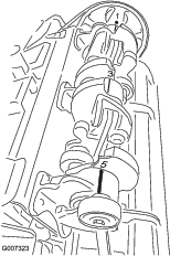
ProCore 1298 (Figure 42)
This unit is comprised of 2 independent coring heads with 6 arms each. The timing of either coring head is not dependent on the adjacent coring head. The timing marks are easily identified by the numbers cast into the crank arm castings and the raised locator on the bearing housings. The #1 arm always starts with the drive pulley.
Removing the Machine from the Traction Unit
Important: Refer to the PTO driveshaft owner’s manual for additional operating and safety information.
-
Park the traction unit and machine on a level surface, disengage the PTO, engage the parking brake, shut off the engine, remove the key, and wait for all moving parts to stop before leaving the operator's seat.
-
Install the storage stands and secure them to the machine with the lynch pins (Figure 43).
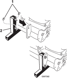
Note: You can store the machine on the original shipping pallet.
-
Slowly lower the machine until the storage stands contact the ground.
-
Loosen the locking nut and rotate the upper adjusting link to release the tension between the machine and the traction unit.
-
Remove the lynch pin and the top link pin securing the center link to the bracket. Retain the lynch pin and the top link pin with the machine.
-
Disconnect the safety shield chains from the traction unit PTO (CE only).
-
Pull back on the lock collar to disconnect the PTO driveshaft from the PTO output shaft on the traction unit.
-
Slide the PTO driveshaft back and remove it from the traction unit.
-
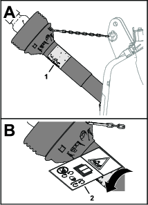
Support the PTO driveshaft by connecting the PTO tether to the PTO shield to prevent the driveshaft from contacting the ground (Figure 44).
-
Remove the lynch pins and slide the lower link arms off the hitch pins.
Retain the lynch pins with the machine.

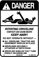
 , which means
Caution, Warning, or Danger—personal safety instruction. Failure
to comply with these instructions may result in personal injury or
death.


