| Maintenance Service Interval | Maintenance Procedure |
|---|---|
| Before each use or daily |
|
Introduction
A walking operator controls this machine, and it is intended to be used by professional, hired operators in commercial applications. The machine is designed primarily for aerating large areas on well-maintained lawns in parks, golf courses, sports fields, and on commercial grounds. Using this product for purposes other than its intended use could prove dangerous to you and bystanders.
Read this information carefully to learn how to operate and maintain your product properly and to avoid injury and product damage. You are responsible for operating the product properly and safely.
Visit www.Toro.com for product safety and operation training materials, accessory information, help finding a dealer, or to register your product.
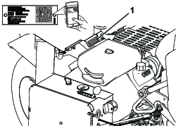
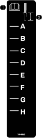
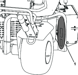
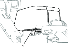
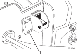
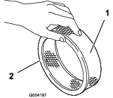
Whenever you need service, genuine Toro parts, or additional information, contact an Authorized Service Dealer or Toro Customer Service and have the model and serial numbers of your product ready. Figure 1 identifies the location of the model and serial numbers on the product. Write the numbers in the space provided.
Important: With your mobile device, you can scan the QR code (if equipped) on the serial number plate to access warranty, parts, and other product information.
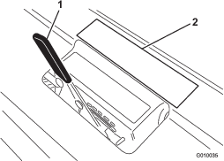
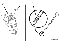
This manual identifies potential hazards and has safety messages identified by the safety-alert symbol (Figure 2), which signals a hazard that may cause serious injury or death if you do not follow the recommended precautions.

This manual uses 2 words to highlight information. Important calls attention to special mechanical information and Note emphasizes general information worthy of special attention.
This product complies with all relevant European directives; for details, please see the separate product specific Declaration of Conformity (DOC) sheet.
Because in some areas there are local, state, or federal regulations requiring that a spark arrester be used on the engine of this machine, a spark arrester is available as an option. If you require a spark arrester, contact your authorized Toro distributor. Genuine Toro spark arresters are approved by the USDA Forestry Service.
The enclosed engine owner's manual is supplied for information regarding the US Environmental Protection Agency (EPA) and the California Emission Control Regulation of emission systems, maintenance, and warranty. Replacements may be ordered through the engine manufacturer.
Warning
CALIFORNIA
Proposition 65 Warning
The engine exhaust from this product contains chemicals known to the State of California to cause cancer, birth defects, or other reproductive harm.
Battery posts, terminals, and related accessories contain lead and lead compounds, chemicals known to the State of California to cause cancer and reproductive harm. Wash hands after handling.
Safety
General Safety
This product is capable of causing personal injury. Always follow all safety instructions to avoid serious personal injury.
-
Read and understand the contents of this Operator’s Manual before starting the engine.
-
Use your full attention while operating the machine. Do not engage in any activity that causes distractions; otherwise, injury or property damage may occur.
-
Do not put your hands or feet near moving components of the machine.
-
Do not operate the machine without all guards and other safety protective devices in place and working on the machine.
-
Keep the machine away from bystanders while it is moving.
-
Keep clear of any discharge opening. Keep bystanders and pets away from the machine.
-
Keep children out of the operating area. Never allow children to operate the machine.
-
Stop the machine, shut off the engine, engage the parking brake, remove the key, and wait for all moving parts to stop before servicing, fueling, or unclogging the machine.
Improperly using or maintaining this machine can result in injury.
To reduce the potential for injury, comply with these safety instructions
and always pay attention to the safety-alert symbol  , which means Caution, Warning,
or Danger—personal safety instruction. Failure to comply with
these instructions may result in personal injury or death.
, which means Caution, Warning,
or Danger—personal safety instruction. Failure to comply with
these instructions may result in personal injury or death.
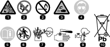
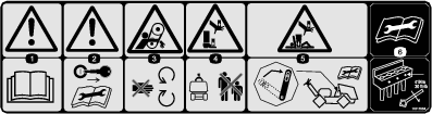
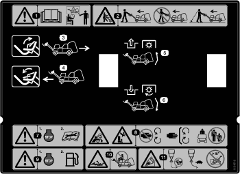
Safety and Instructional Decals
 |
Safety decals and instructions are easily visible to the operator and are located near any area of potential danger. Replace any decal that is damaged or missing. |


Setup
Note: The front of the machine is located at the operator handle, and is the normal operator position. Left and right are in relation to the direction of travel as you walk with machine following you.
Note: To raise the coring head after uncrating the machine, start the engine and press the Reset button. Refer to Starting the Engine and Resetting the System Control Circuit for more information.
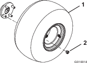
Installing the Rear Wheels
Parts needed for this procedure:
| Wheel assembly | 2 |
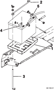
Installing the Handle
Parts needed for this procedure:
| Locknut (1/2 inch) | 3 |
| Cable guide | 1 |
| Bolt (5/16 x 1/2 inch) | 2 |
-
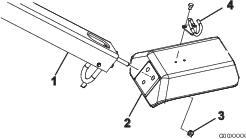
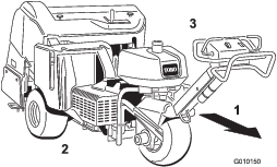
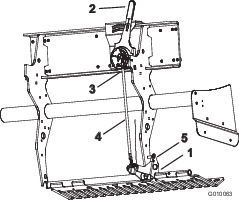
Carefully rotate the handle to the front of the machine. Use caution not to damage the cables.
-
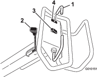
Insert the handle mounting studs into the holes in the fork (Figure 4).
-
Secure handle studs to fork (Figure 4) with 3 locknuts (1/2 inch).
-
Insert the cable guide around the cables.
-
Mount the cable guide to the top of the fork (Figure 4) with 2 bolts (5/16 x 1/2 inch).
Securing the Rear Hood (CE Only)
Parts needed for this procedure:
| Latch lock | 2 |
| Tap bolt | 2 |
| Internal tooth lock washer | 2 |
If you are setting up this machine for use in the European Union (CE), secure the rear hood as follows to comply with CE regulations.
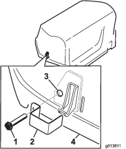
Securing the Belt Cover (CE Only)
Parts needed for this procedure:
| Lanyard | 1 |
| Pop rivet | 1 |
| Bolt (1/4 x 1 inch) | 1 |
| Locknut (1/4 inch) | 1 |
If you are setting up this machine to be compliant with CE, secure the belt cover as follows.
-
Locate the hole in the belt cover next to the latch lever (Figure 6 and Figure 7).
-
Using the hole in the belt cover, install the lanyard assembly with a pop rivet (Figure 7).

-
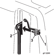
Thread the bolt into the latch lever (Figure 8).
Applying the CE Decal and the Production Year Decal
CE Only
Parts needed for this procedure:
| CE decal | 1 |
| Production year decal | 1 |
After completing all the necessary CE requirements, apply the CE decal and the production year decal to the fork leg (Figure 9).
Installing the Tine Holders, Turf Guards, and Tines
A wide selection of tine holders, turf guards, and tines are available for the machine. Install the setup appropriate for your application as described in Installing Tine Holders, Turf Guards, and Tines.
Charging the Battery
Charge the battery before first use; refer to Charging the Battery.
Product Overview
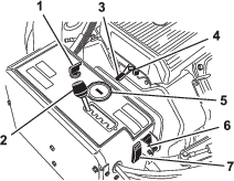
Become familiar with all the controls before you start the engine and operate the machine.
Traction Bail
To move forward, move the traction bail forward. To move rearward, move the traction bail rearward (Figure 11).
-
The farther you move the traction bail, the faster the machine moves.
-
To stop the machine, release both traction bails.
Parking-Brake Lever
Important: Always engage the parking brake when you stop the machine or leave it unattended.
-
To engage the parking brake, move the parking-brake lever toward the operator handle (Figure 11).
Note: You may need to move the machine forward or backward slightly when engaging the parking brake.
-
To disengage the parking brake, move the parking-brake lever away from the operator handle.
Note: You may need to move the machine forward or backward slightly when disengaging the parking brake.
Oil-Pressure Warning Light
The oil-pressure warning light (Figure 11) illuminates when the engine-oil pressure drops below a safe level. If low oil pressure ever occurs, shut off the engine and determine the cause. Repair the damage before starting the engine again.
Raise, Lower/Engage Switch
Raise—Press the top of the switch (Figure 11) to raise the coring head and disengage the coring head. The engine must be running to generate lift pressure. If the coring head is below the transport height, refer to Resetting the System Control Circuit.
Lower/Engage—Press the bottom of the switch (Figure 11) to lower and engage the coring head. The traction bail must be in the forward position to activate the switch.
Danger
When the coring head is running, it can injure your hands and feet.
Keep hands and feet away from the coring head. Ensure that the coring head area is clear of any obstructions before lowering it.
To lower the coring head without engaging it, turn the ignition key to the RUN position (without the engine running), move the traction bail to the forward position, and press the bottom of the switch.
Ignition Switch and Key
Use the ignition switch (Figure 12), to start and shut off the engine. The switch has 3 positions:
-
START—rotate key clockwise to the START position to engage the starter motor.
-
RUN—when the engine starts, release the key and it moves automatically to the ON position.
-
OFF—rotate the key counterclockwise to the OFF position to shut off the engine.
Aerator Spacing Lever
Move aerator spacing lever (Figure 12) to desired hole spacing or to T for transport.
Throttle Lever
Use the throttle lever (Figure 12) to control the engine speed. Moving throttle lever forward increases engine speed (FAST position); backward decreases engine speed (SLOW position). The engine speed regulates the speed of the coring head and controls the ground speed of the machine.
Hour Meter/Tachometer
-
When the engine shuts off, the hour meter/tachometer (Figure 12) displays the number of hours the engine has run.
-
When the engine is running, hour meter/tachometer displays the engine speed in revolutions per minute (rpm).
-
The hour meter/tachometer displays the following maintenance reminders:
-
After the first 50 hours of operation and then after every 100 hours (e.g., 150, 250, 350, etc.), the screen displays “CHG OIL” to remind you to change the engine oil.
-
After every 100 hours (e.g., 100, 200, 300, etc.), the screen displays “SVC” to remind you to perform the other maintenance procedures based on a 100, 200, or 500 hour schedule.
Note: These reminders display starting 3 hours prior to the service interval time and flash at regular intervals for 6 hours.
-
Choke
Use the choke when starting a cold engine (Figure 12).
Manual Ground Follow Selector Switch
Rotate the switch to the down position to turn off the TrueCore feature (Figure 12). Remove the bolt to access the manual ground switch.
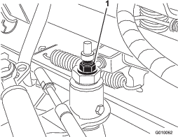
System Reset Switch
Press the system reset switch (Figure 12) to raise the coring head if the machine becomes disabled (e.g., the machine runs out of fuel).
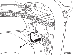
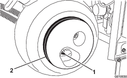
Fuel-Shutoff Valve
Use the fuel-shutoff valve to control fuel from the fuel tank (Figure 13).
Aeration Depth Lever
Move the lever to the desired depth of aeration (Figure 14).
Note: Specifications and design are subject to change without notice.
| Width | 127 cm (50.1 inches) |
| Wheel base | 113 cm (44.5 inches) |
| Track width | 97 cm (38.3 inches) |
| Coring width | 122 cm (48 inches) |
| Length | 265 cm (104.5 inches) |
| Head height (raised) | 114 cm (45 inches) |
| Head height (lowered) | 93 cm (36-1/2 inches) |
| Height, handle | 104 cm (41 inches) |
| Ground clearance | 12 cm (4.8 inches) |
| Forward speed | 0 to 6 kph (0 to 3-1/2 mph) |
| Reverse speed | 0 to 3 kph (0 to 2 mph) |
| Net weight | 721 kg (1,590 lb) |
Attachments/Accessories
A selection of Toro approved attachments and accessories is available for use with the machine to enhance and expand its capabilities. Contact your authorized Toro distributor or go to www.Toro.com for a list of all approved attachments and accessories.
To ensure optimum performance and continued safety certification of the machine, use only genuine Toro replacement parts and accessories. Replacement parts and accessories made by other manufacturers could be dangerous, and such use could void the product warranty.
Refer to the tine configuration table that follows for the tine head, turf guard, and tine information:
| Tine Head Description | Tine Head Spacing | Shank Size | Tine Quantity | Turf Guard Type (quantity) |
|---|---|---|---|---|
| 2x5 Mini-Tine Head | 41 mm (1.60 inch) | 9.5 mm (3/8 inch) | 60 | 5-Tine—short (2) |
| 5-Tine—long (1) | ||||
| 1x6 Mini-Tine Head | 32 mm (1.25 inch) | 9.5 mm (3/8 inch) | 36 | 6-Tine—short (2) |
| 6-Tine—long (1) | ||||
| 3 Tine Head (7/8 inch) | 66 mm (2.60 inch) | 22.2 mm (7/8 inch) | 18 | 3-Tine—short (2) |
| 3-Tine—long (1) | ||||
| 3 Tine Head (3/4 inch) | 66 mm (2.60 inch) | 19.5 mm (3/4 inch) | 18 | 3-Tine—short (2) |
| 3-Tine—long (1) | ||||
| 4 Tine Head (3/4 inch) | 51 mm (2.00 inch) | 19.5 mm (3/4 inch) | 24 | 4-Tine—short (2) |
| 4-Tine—long (1) | ||||
| 5 Needle-Tine Head | 41 mm (1.60 inch) | — | 30 | 5-tine—short (2) |
| 5-Tine—long (1) |
Operation
Note: Determine the left and right sides of the machine from the normal operating position.
Before Operation
Before Operation Safety
General Safety
-
Never allow children or untrained people to operate or service the machine. Local regulations may restrict the age of the operator. The owner is responsible for training all operators and mechanics.
-
Become familiar with the safe operation of the equipment, operator controls, and safety signs.
-
Know how to stop the machine and shut off the engine quickly.
-
Check that operator-presence controls, safety switches, and shields are attached and functioning properly. Do not operate the machine unless they are functioning properly.
-
Before operating, always inspect the machine to ensure that the tines are in good working condition. Replace worn or damaged tines.
-
Inspect the area where you plan to use the machine and remove all objects that the machine could strike.
-
Locate and mark all electrical or communication lines, irrigation components, and other obstructions in the area to be aerated. Remove the hazards, if possible, or plan how to avoid them.
-
Park the machine on a level surface; engage the parking brake; shut off the engine; remove the key; and wait for all movement to stop before leaving the machine.
Fuel Safety
-
Use extreme care in handling fuel. It is flammable, and its vapors are explosive.
-
Extinguish all cigarettes, cigars, pipes, and other sources of ignition.
-
Do not remove the fuel cap or fill the fuel tank while the engine is running or hot.
-
Do not add or drain the fuel in an enclosed space.
-
Do not store the machine or fuel container where there is an open flame, spark, or pilot light, such as on a water heater or other appliance.
-
If you spill fuel, do not attempt to start the engine; avoid creating any source of ignition until the fuel vapors have dissipated.
Adding Fuel
Fuel Specification
-
For best results, use only clean, fresh (less than 30 days old), unleaded gasoline with an octane rating of 87 or higher ((R+M)/2 rating method).
-
Ethanol: Gasoline with up to 10% ethanol (gasohol) or 15% MTBE (methyl tertiary butyl ether) by volume is acceptable. Ethanol and MTBE are not the same. Do not use gasoline with 15% ethanol (E15) by volume. Never use gasoline that contains more than 10% ethanol by volume, such as E15 (contains 15% ethanol), E20 (contains 20% ethanol), or E85 (contains up to 85% ethanol ). Using unapproved gasoline may cause performance problems and/or engine damage which may not be covered under warranty.
-
Do not use fuel containing methanol.
-
Do not store fuel either in the fuel tank or fuel containers over the winter unless you use a fuel stabilizer.
-
Do not add oil to fuel.
Important: Do not use fuel additives other than a fuel stabilizer/conditioner. Do not use fuel stabilizers with an alcohol base such as ethanol, methanol, or isopropanol.
Important: Do not use methanol, gasoline containing methanol, or gasohol containing more than 10% ethanol because the fuel system could be damaged. Do not mix oil with fuel.
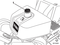
Filling the Fuel Tank
Fuel tank capacity: 26.5 L (7 US gallons)
-
Park the machine on a level surface, shut off the engine, engage the parking brake, and remove the key.
-
Clean around the fuel-tank cap and remove it (Figure 15).
-
Add fuel to the fuel tank, until the level is 6 mm to 13 mm (1/4 to 1/2 inch) below the bottom of the filler neck.
Important: This space in the tank allows fuel to expand. Do not fill the fuel tank completely full.
-
Install the fuel-tank cap securely.
-
Wipe up any spilled fuel.
Performing Daily Maintenance
Before starting the machine each day, perform the following daily-check procedures:
The Safety Interlock System
Caution
If safety interlock switches are disconnected or damaged the machine could operate unexpectedly causing personal injury.
-
Do not tamper with the interlock switches.
-
Check the operation of the interlock switches daily and replace any damaged switches before operating the machine.
Understanding the Safety Interlock System
The safety interlock system prevents the engine from starting unless the traction bail is in the NEUTRAL position.
Testing the Safety Interlock System
-
If running, shut off the engine.
-
While holding the traction bail forward or backward, start the engine.
The engine should not start.
-
Move the traction bail to the NEUTRAL position and start the engine.
-
Move the machine to an area of turf.
-
Engage the PTO and lower the coring head.
-
Release the traction lever or moved it to the neutral position.
The coring head should raise and stop rotating.
If the safety system does not operate as described above, have an authorized Toro distributor repair the safety system immediately.
During Operation
During Operation Safety
-
The owner/operator can prevent and is responsible for accidents that may cause personal injury or property damage.
-
Wear appropriate clothing, including eye protection; long pants; substantial, slip-resistant footwear; and hearing protection. Tie back long hair, secure loose clothing, and do not wear loose jewelry.
-
Do not operate the machine when tired, ill, or under the influence of alcohol or drugs.
-
Never carry passengers on the machine and keep bystanders and pets away from the machine during operation.
-
Operate the machine only in good visibility to avoid holes or hidden hazards.
-
Keep your hands and feet away from the tines.
-
Look behind and down before backing up to be sure of a clear path.
-
Stop the machine, shut off the engine, remove the key, wait for all moving parts to stop, and inspect the tines after striking an object or if there is an abnormal vibration in the machine. Make all necessary repairs before resuming operation.
-
Always maintain proper tire pressure.
-
Reduce traction speed on rough roads and surfaces.
Slope Safety
-
Slopes are a major factor related to loss of control and rollover accidents, which can result in severe injury or death. You are responsible for safe slope operation. Operating the machine on any slope requires extra caution.
-
Evaluate the site conditions to determine if the slope is safe for machine operation including surveying the site. Always use common sense and good judgment when performing this survey.
-
Review the slope instructions listed below for operating the machine on slopes and review the conditions to determine whether you can operate the machine in the conditions on that day and at that site. Changes in the terrain can result in a change in slope operation for the machine.
-
Avoid starting, stopping, or turning the machine on slopes. Avoid making sudden changes in speed or direction. Make turns slowly and gradually.
-
Do not operate a machine under any conditions where traction, steering, or stability is in question.
-
Remove or mark obstructions such as ditches, holes, ruts, bumps, rocks, or other hidden hazards. Tall grass can hide obstructions. Uneven terrain could overturn the machine.
-
Be aware that operating the machine on wet grass, across slopes, or downhill may cause the machine to lose traction. Loss of traction to the drive wheels may result in sliding and a loss of braking and steering.
-
Use extreme caution when operating the machine near drop offs, ditches, embankments, water hazards, or other hazards. The machine could suddenly roll over if a wheel goes over the edge or the edge caves in. Establish a safety area between the machine and any hazard.
Starting the Engine
-
Release the traction bail and engage the parking brake.
-
Use the choke as follows:
-
Before starting a cold engine, move the choke control to the ON position.
-
When starting a warm or hot engine, you may not need to use the choke.
-
-
Move the throttle lever to the FAST position before starting a cold engine.
-
Turn the ignition key to start. When the engine starts, release the key.
Important: Do not engage the starter for more than 10 seconds at a time. If the engine fails to start, allow a 30-second cooldown period between attempts. Failure to follow these instructions can burn out the starter motor.
-
After the engine starts, move the choke to the OFF position. If the engine stalls or hesitates, move the choke back to the ON position for a few seconds. Then move the throttle lever to desired setting. Repeat this as required.
Shutting Off the Engine
-
Move the throttle lever to the SLOW position.
-
Let the engine idle for 60 seconds.
-
Turn the ignition key to the OFF position and remove the key.
-
Close the fuel-shutoff valve before transporting or storing the machine.
Important: Close the fuel-shutoff valve before transporting the machine on a trailer or storing the machine. Engage the parking brake before transporting the machine. Remove the key as the fuel pump may run and cause the battery to lose charge.
Caution
Children or bystanders may be injured if they move or attempt to operate the machine while it is unattended.
Always remove the ignition key and engage the parking brake when leaving the machine unattended, even if just for a few minutes.
Using the Machine
-
Start the engine.
-
Disengage the parking brake.
-
Look in the direction of your planned path to ensure that it is clear.
-
Move the traction bail down to drive the machine forward.
Walk in a forward direction while operating the machine, do not walk and face rearward when operating the machine.
-
Engage the PTO and lower the coring head.
-
Disengage the PTO and raise the coring head.
-
To stop the machine, release the traction bail.
Setting the Coring Depth
-
Park the machine on a level surface, shut off the engine, engage the parking brake, and remove the key.
-
Select the preferred tine for your application.
-
Lay the tine on the tine depth decal (Figure 16) with 1 end lined up with the desired depth of aeration (refer to the tine overlay on the decal).
-
Determine which letter setting the other end of the tine lines up with and set the depth control lever to the corresponding letter setting.
Note: As the tine wears, you may be able to reset the depth setting to account for that wear. For instance, if your new tine depth setting has you in the G setting, you can reset to the H setting after 6 mm (1/4 inch) of tine wear.
Using the Line Marker
Use the line marker to align aeration rows (Figure 17).
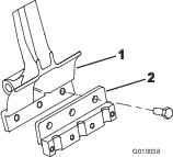
Supporting the Coring Head with the Service Latch
Install the service latch before performing service on the coring head or when storing the machine for more than a couple of days.
Danger
If the coring head is raised and not latched, it can lower unexpectedly and injure you or bystanders.
Any time you service the coring head, including changing of tines or turf guards, use the service latch to secure coring head in the raised position.
-
Raise the coring head.
-
Park the machine on a level surface, shut off the engine, engage the parking brake, and remove the key.
-
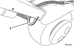
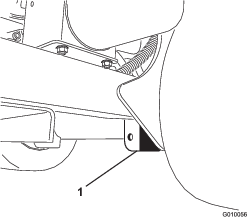
Remove the clip ring securing the service latch in the stowed position (Figure 18).
-
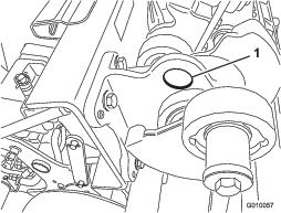
Pivot the service latch rearward and insert it onto the coring head pin (Figure 19). Secure the latch with the clip ring.
Setting Up Manual Ground Following
The manual depth setting spacers are required only when the TrueCore® ground following system does not function because of damage to the feedback system (turf guards, tie rod, and actuator assembly) or if you need maximum coring depth.
-
Park the machine on a level surface, shut off the engine, engage the parking brake, and remove the key.
-
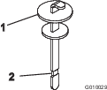
Remove the lynch pin retaining the spacers and depth pins (Figure 20).
-
Position the spacers above or below the bracket to attain the desired coring depth.
-
Thick spacers equate to 19 mm (3/4 inch) increments.
-
Thin spacer equates to 9.5 mm (3/8 inch) depth increment.
-
With all spacers on the top side, the depth setting is 10.7 cm (4-1/4 inches).
-
-
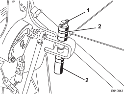
Remove the locking bolt and nut from the selector switch (Figure 21).
-
Rotate the switch to the down position to turn off True Core feature.
-
To prevent the setting from accidentally changing, install the locking bolt and nut.
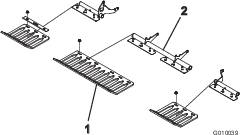
Installing Tine Holders, Turf Guards, and Tines
A wide selection of tine holders, turf guards, and tines are available for the machine. Choose the required components per the accessory chart in Attachments and Accessories.
-
Raise the coring head and lock it in position with the service latch.
-
Park the machine on a level surface, shut off the engine, engage the parking brake, and remove the key.
-
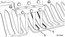
Mount a tine holder to each tine arm (Figure 22) with 3 bolts (1/2 x 1-1/4 inches). Torque the bolts to 101.6 N∙m (75 ft-lb).
Note: The bolts are parts in the tine holder kits.
-
Loosely install the turf guards to the turf guard brackets with 4 turf guard clamps and 12 flange nuts (Figure 23). Do not tighten the fasteners.
Note: The factory ships turf guard clamps and flange nuts secured to the turf guard brackets (Figure 23).
-
Loosely install a tine clamp to each tine holder (Figure 24) with 4 bolts (3/8 x 1-1/2 inches). Do not tighten the bolts.
-
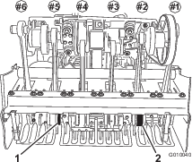
Install tines into the #2 and #5 tine holders (Figure 25) Tighten the bolts.
-
Check that the tines line up with the center of the gaps in the turf guards (Figure 26). Adjust the turf guards as required and tighten the nuts.
-
Install the remaining tines into the #1, 3, 4, and 6 tine holders. Torque all tine holder bolts to 40.6 N∙m (30 ft-lb).
Replacing Tines
Refer to Installing the Tine Holders, Turf Guards, and Tines for illustrations.
-
Raise the coring head and lock it in position with the service latch.
-
Park the machine on a level surface, shut off the engine, engage the parking brake, and remove the key.
-
Loosen the tine holder retaining bolts and remove the old tines.
-
Insert the new tines into the tine holder.
-
Tighten the bolts to the recommended torque level.
-
Repeat this procedure on the remaining arms.
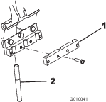
Adjusting the Weight Transfer
The machine transfers weight from the traction unit to the coring head to help maintain hole depth in various soil structures. However, if the soil structure is firm enough to not allow full aeration depth, the coring head may need additional weight transfer. To increase the down pressure of the weight transfer springs, proceed as follows:
Warning
Sudden release of the spring plates could cause injury.
Acquire the help of another person to help adjust the weight transfer spring.
-
Park the machine on a level surface, shut off the engine, engage the parking brake, and remove the key.
-
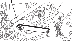
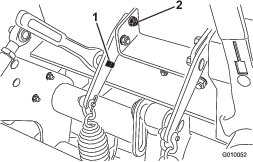
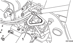
Loosen the carriage bolt nuts securing the spring brackets to the coring head (Figure 27). Do not remove them.
-
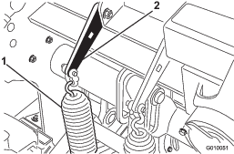
Insert a 1/2 inch ratchet or breaker bar into the square hole in the spring plate (Figure 28).
-
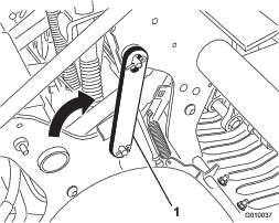
Hold the ratchet or breaker bar to relieve the tension on the spring plate and remove the rear carriage bolt.
-
Rotate the spring plate until it aligns with the other hole, insert the carriage bolt, and tighten the nuts.
Note: Rotating the spring plates upward increases the weight transfer.
Adding Additional Weight
With the increased weight transfer, it is possible to aerate firm enough ground that the weight transfer begins to lift the rear 2 tires off the ground. This may lead to irregular hole spacing.
If this occurs, you can add an additional weight plate to the rear frame axle tube. Each cast weight adds 28.5 kg (63 lb) to the machine. You can add up to 2 plates. Refer to the Parts Catalog for these part numbers.
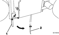
Pushing/Pulling the Machine by Hand
Important: Do not tow the machine faster than 1.6 km/h (1 mph) because hydraulic component damage may occur.
-
Park the machine on a level surface, shut off the engine, engage the parking brake, and remove the key.
-
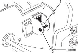
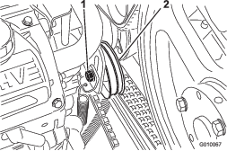
Locate the bypass valve between the engine and hydrostatic pump (Figure 29).
-
Using a 5/8 inch wrench, rotate the bypass valve counterclockwise 1 turn. This allows the hydraulic fluid to bypass the pump enabling the wheels to turn (Figure 29).
Important: Do not rotate the bypass valve more than 1 turn. This prevents the valve from coming out of the body and causing fluid to run out.
Important: Do not push/pull the machine more than 30.5 m (100 ft) or faster than 0.6 km/h (1 mph) because hydraulic component damage may occur.
-
Disengage the parking brake before pushing/pulling the machine.
Important: Do not operate the engine with the bypass valve open for more than 10 to 15 seconds.
-
To operate the machine again, rotate the bypass valve clockwise 1 turn (Figure 29).
Note: Do not overtighten the bypass valve.
Note: You must close the bypass valve to drive the machine. Do not try to operate traction system with the bypass valve open.
Resetting the System Control Circuit
If the coring head remains in the aerating position (run out of fuel, forget to install service latch for storage, mechanical failure of engine or pump, etc.) the electrical system that controls the hydraulic solenoid coils and the electric clutch disables to prevent unintended movement of the coring head without the intentionally resetting the system.
-
Start the engine.
-
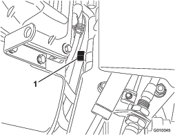
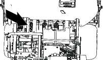
Press the system reset switch (Figure 30).
The coring head raises and the electrical-control circuit resets.
Note: If you cannot run the engine, crank the engine with the starter while pressing the system reset switch until the coring head clears the ground.
Moving the Machine when the Coring Head is Lowered
If the engine fails or you cannot be start it with the coring head lowered and the tines engaged in the soil, perform the following steps:
-
Remove the tine holders from the stomper arms.
-
Open the bypass valve 1 turn.
-
Pull/push the machine to a nearby location to continue service or load onto a trailer.
Important: Do not pull/push machine for more than 30.5 m (100 ft) and no faster than 1.6 km/h (1 mph), because hydraulic damage may occur.
Operating Tips
General
Warning
Contacting obstacles with the machine may cause you to lose control of it.
Always be aware of obstacles at the job site. Plan your aeration path to avoid contact with any obstacle by you or the machine.
-
Make very gradual turns when aerating. Never make sharp turns with the coring head engaged. Plan your aeration path before lowering the aerator.
-
Always maintain awareness of what lies ahead in the direction of forward travel. Avoid operation in close proximity of buildings, fences, and other equipment.
-
Look behind frequently to ensure that the machine operates properly, and you maintain alignment with previous pass.
-
Always clear the area of all damaged machine parts, such as broken tines, etc., to prevent their being picked up by mowers or other turf maintenance equipment.
-
Replace broken tines and inspect and correct damage to those still usable. Repair any other machine damage before commencing operation.
-
When aerating with less than the full width of the machine, you may remove tines, but the tine heads should remain installed on the stomper arms to ensure proper balance and operation of the machine.
-
This machine aerates deeper than most greens aerators. On native or modified push-up greens and tees, the deeper depth and longer hollow tines may have difficulty ejecting the complete core. This is due to harder native soil that sticks in the end of the tine. Side-eject greens/tees tines from Toro stay cleaner and reduce the time required to clean the tines out. You will eventually eliminate this condition with continued aeration and top-dressing programs.
Hard Ground
If the ground is too firm to obtain the desired coring depth, the coring head can get into a bouncing rhythm. This is due to the hard pan the tines are attempting to penetrate. Correct this condition by attempting the following:
-
Do not aerate if ground is too hard or dry. You obtain best aeration results after a rain or watering the turf the previous day.
-
Change to a 3-tine head, if attempting to use the 4-tine head or reduce the number of tines per stomper arm. Attempt to maintain a symmetrical tine configuration to evenly load the stomper arms.
-
If ground is hard packed, reduce aerator penetration (depth setting), clean up the cores, water the turf, and aerate again at a deeper penetration.
Aeration of soil types built on top of hard subsoils (i.e., soil/sand placed over rocky soil) can cause undesired hole quality. This occurs when the aeration depth is greater than the built up soil and the subsoil is too hard to penetrate. When the tines contact this harder subsoil, the aerator may lift and cause the top of the holes to become elongated. Reduce the aerating depth sufficiently to avoid penetration into the hard subsoil.
Entrance/Exit Hole Quality
The entrance/exit hole quality is deteriorating when the machine produced the following results:
-
The hole quality upon entrance is slotted (pulled forward).
-
The coring head fails to engage before contacting the turf.
Check the following:
-
The engagement position switch (no. 3 switch location on H-frame) may need adjustment; refer to Adjusting the #3 Proximity Switch.
-
Your machine may have a worn or slipping clutch; refer to the Service Manual for your machine.
Adjusting the #4 Proximity Switch
The #4 proximity switch is by default positioned at the lowest setting, allowing for improved entry hole performance and depth; switch #4 should be assembled in the lowest position during most aeration activities.
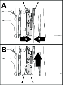
If aerating at a shallow depth causes the coring head to overshoot the tine depth, or if you are experiencing coring head bounce, adjust the #4 proximity switch to a higher setting on the H-bracket when aerating at shallow depths (Figure 32).
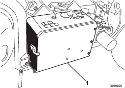
Adjusting the #3 Proximity Switch
-
Park the machine on a level surface; engage the parking brake; shut off the engine; remove the key; and wait for all movement to stop before leaving the machine
-
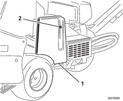
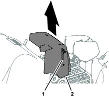
Lift the latch lever for the hood and lift the hood from the machine (Figure 31).
-
Verify that the proximity-switch assembly (outboard of the H-frame) is no more than 1.5 mm (0.06 inches) from the target plate (Figure 32).
-
Verify that the #3 proximity switch is functioning properly.
-
If needed, loosen the locknut and carriage bolt that secure the switch mounting plate and lift it to the highest position and secure the mounting plate (Figure 32).
Note: Raising the switch causes the clutch to engage sooner.
-
Tighten the locknut (Figure 32).
-
Align the bracket of the hood with the hood mount on the machine.
-
Assemble the hood to the machine and ensure that the latch secures the hood.
-
Check the entrance/exit hole quality.
Important: If the coring head fails to start before entrance and the position switch is located as high as permissible, the electric clutch may have deteriorated sufficiently to cause a delay in engagement. Contact your authorized Toro distributor or refer to the Service Manual.
Mini Tine (Quad Tine)
Because of the double row design, the mini-tine coring head requires the hole spacing to be set at 6.3 cm (2-1/2 inches). Ground speed is critical to maintain the appearance of 3.2 cm (1-1/4 inches) hole spacing. Refer to Adjusting Hole Spacing if your hole spacing requires a small change.
With the mini tine head or larger solid tine use, the turf root structure is important to preventing turf damage due to tearing of the root zone. If the center 2 arms begin to lift the turf or damage to the root zone is excessive, proceed as follows:
-
Increase the hole spacing
-
Decrease tine size
-
Decrease tine depth
-
Remove some of the tines
The lifting action that solid tines creates when it is pulled from the turf may cause turf damage. This lift can tear the root zone if the density of tines or diameter of tines is too high.
Front Hole Dimpled or Pushed (Solid Tines or Softer Soil Conditions)
When aerating with longer solid tines (i.e., 3/8 x 4 inches long) or needle type tines, the front of the holes may become slotted or tufted. To regain excellent hole quality for this configuration, slow the engine high idle speed down to 2800 to 2900 rpm. Because traction and coring head speeds increase and decrease together with engine speed, hole spacing is not affected.
If slowing the engine speed does not work to the remedy hole quality for the larger solid tines, the Roto-Link damper mechanism may require a stiffer setting. A stiffer Roto-Link setting may help eliminate the front of the hole from being deformed. However, under most conditions, the factory setting works best.
Note: Alter half of the Roto-Links (3 arms) and test the difference on a sample plot.
-
Park the machine on a level surface, shut off the engine, engage the parking brake, and remove the key.
-
Remove the lock nuts securing the Roto-Link damper assembly to the coring head frame.
-
Remove the top damper-spacer that is 1.25 cm (1/2 inch) thick and re-secure the Roto-Link damper assembly to the coring head frame. Be sure to use the hardened D-washer.
-
Loosen the bolts securing the bumper plate.
-
Slide the bumper plate forward and secure the bolts. This allows the Roto-Link bumpers to oscillate properly.
Take the machine to a test area and compare the hole quality. If improved, complete this procedure with remaining Roto-Link damper assemblies.
Note: You must reverse the position of the Roto-Link damper if you change back to a coring style tine or any of the mini-tines.
After Operation
After Operation Safety
-
Park the machine on a level surface; engage the parking brake; shut off the engine; remove the key; and wait for all movement to stop before leaving the machine.
-
Keep all parts of the machine in good working condition and all hardware tightened.
-
Replace all worn, damaged, or missing decals.
Cleaning the Machine
| Maintenance Service Interval | Maintenance Procedure |
|---|---|
| Before each use or daily |
|
-
Thoroughly wash the machine.
Use a brush to remove caked-on material.
Note: Use a garden hose without a nozzle to avoid forcing water past the seals and contaminating bearing grease.
-
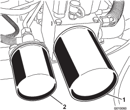
Use mild detergent to clean the covers.
After cleaning, apply a coat of auto wax periodically to maintain the glossy finish of the cover.
-
Inspect the machine for damage, oil leaks, and component and tine wear.
-
Remove, clean, and oil the tines. Spray a light oil mist on coring head bearings (crank and damper links).
Important: Secure the coring head with the service latch if you store the machine for more than a couple of days.
Locating the Tie-Down Points
Hauling the Machine
Warning
Driving the machine on street or roadway without turn signals, lights, reflective markings, or a slow-moving vehicle emblem is dangerous and can lead to accidents causing personal injury.
Do not operate the machine on a public street or roadway.
Important: Use full-width ramps for loading the machine onto a trailer or truck.
-
Load the machine onto the trailer or truck (coring head forward—preferred).
-
Engage the parking brake, shut off the engine, and remove the key.
-
Secure the coring head with the service latch; refer to Supporting the Coring Head with the Service Latch.
-
Close the fuel-shutoff valve; refer to Fuel-Shutoff Valve.
-
At the tie-down points, bind the machine to the trailer or truck with cables, chains, or straps.
| Weight | 721 kg (1,590 lb) or 805 kg (1,775 lb) with 2 optional weights |
| Width | 130 cm (51 inches) minimum |
| Length | 267 cm (105 inches) minimum |
| Ramp Angle | 3.5/12 pitch (16°) maximum |
| Load Direction | Coring head forward (preferred) |
| Vehicle Tow Capacity | Greater than gross trailer weight (GTW) |
Important: Do not use the Hydroject trailer/tote to trailer this machine.
Maintenance
Note: Determine the left and right sides of the machine from the normal operating position.
Maintenance Safety
Caution
If you leave the key in the ignition switch, someone could accidently start the engine and seriously injure you or other bystanders.
Engage the parking brake, shut off the engine, remove the key, and secure the coring head with the service latch before servicing or adjusting to the machine.
-
Always shut off the machine, remove the key (if equipped), wait for all moving parts to stop, and allow the machine to cool before adjusting, servicing, cleaning, or storing it.
-
Perform only those maintenance instructions described in this manual. If major repairs are ever needed or assistance is desired, contact an authorized Toro distributor.
-
Ensure that the machine is in safe operating condition by keeping nuts, bolts, and screws tight.
-
If possible, do not perform maintenance while the engine is running. Keep away from moving parts.
-
Carefully release pressure from components with stored energy.
-
Check the tine mounting bolts daily to be sure that they are tightened to specification.
-
Ensure that all guards are installed, and the hood is secured shut after maintaining or adjusting the machine.
Recommended Maintenance Schedule(s)
| Maintenance Service Interval | Maintenance Procedure |
|---|---|
| After the first 8 hours |
|
| After the first 50 hours |
|
| Before each use or daily |
|
| Every 25 hours |
|
| Every 50 hours |
|
| Every 100 hours |
|
| Every 200 hours |
|
| Every 500 hours |
|
| Before storage |
|
| Yearly |
|
Important: Refer to your engine owner’s manual for additional maintenance procedures.
Pre-Maintenance Procedures
Important: The fasteners on the covers of this machine are designed to remain on the cover after removal. Loosen all the fasteners on each cover a few turns so that the cover is loose but still attached, then go back and loosen them until the cover comes free. This prevents you from accidentally stripping the bolts free of the retainers.
Raising the Machine
Caution
If the machine is not properly supported by blocks or jack stands, the machine may move or fall, which may result in personal injury.
-
When changing attachments, tires, or performing other service, use the correct blocks, hoists, and jacks.
-
Make sure that the machine is parked on a solid, level surface such as a concrete floor.
-
Prior to raising the machine, remove any attachments that may interfere with the safe and proper raising of the machine.
-
Always chock or block wheels. Use jack stands or solid wood blocks to support the raised machine.
Raising the Front End
-
Park the machine on a level surface, shut off the engine, engage the parking brake, and remove the key.
-
Chock the rear tires to prevent the machine from moving.
Important: To prevent wheel motor damage, do not use the front wheel motor as a jack point.
-
Position the jack securely under the front of the frame (Figure 36).
-
Raise the front of the machine off the ground.
-
Position the jack stands or hardwood blocks under the front of the frame to support the machine.
Raising the Rear End
-
Park the machine on a level surface, shut off the engine, engage the parking brake, and remove the key.
-
Chock the front tire to prevent the machine from moving.
Important: To prevent wheel motor damage, do not use rear wheel motor as a jack point.
-
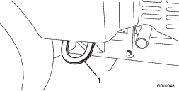
Place the jack securely under the frame plate just inside of the rear wheel (Figure 37).
Note: If available, use a hoist to lift the rear of the machine. Use the eyelets in the coring head bearing housings as hoist attachment points (Figure 38).
-
Raise the rear of the machine off the ground.
-
Position the jack stands or hardwood blocks under the frame to support the machine.
Lubrication
Checking the Coring Head Bearings
| Maintenance Service Interval | Maintenance Procedure |
|---|---|
| Every 500 hours |
|
| Yearly |
|
The machine has no grease fittings to lubricate.
Important: Bearings rarely fail from defects in materials or workmanship. The most common reason for failure is moisture and contamination working its way past the protective seals. Bearings that are greased rely upon regular maintenance to purge harmful debris from the bearing area. Sealed bearings rely on an initial fill of special grease and a robust integral seal to keep contaminants and moisture out of the rolling elements.
The sealed bearings require no lubrication or short term maintenance. This minimizes routine service required and reduces the potential of turf damage due to grease contamination. These sealed bearing packages provide good performance and life under normal use, but periodic inspections of bearing condition and seal integrity should be conducted to avoid downtime. Inspect the bearings seasonally and replace them if they are damaged or worn. Bearings should operate smoothly with no detrimental characteristics such as high heat, noise, looseness, or rust weeping.
Due to the operating conditions these bearing/seal packages are subject to (e.g., sand, turf chemicals, water, impacts, etc.) they are considered normal wear items. Bearings that fail due to causes other than defects in materials or workmanship are typically not covered under warranty.
Note: You can negatively affect the bearings if you do not wash the machine correctly. Do not wash the machine when it is still hot and avoid directing high-pressure or high volume spray at the bearings.
New bearings commonly purge some grease out of the seals on a new machine. This purged grease turns black due to collection of debris, not excessive heat. Wipe this excess grease from the seals after the initial 8 hours. The area around the seal lip may continually appear to be wet; this is not detrimental to bearing life, and keeps the seal lip lubricated.
Engine Maintenance
Engine Safety
-
Shut off the engine before checking the oil or adding oil to the crankcase.
-
Do not change the governor speed or overspeed the engine.
Servicing the Air Cleaner
| Maintenance Service Interval | Maintenance Procedure |
|---|---|
| Every 25 hours |
|
| Every 100 hours |
|
Removing the Filters
-
Park the machine on a level surface, shut off the engine, engage the parking brake, and remove the key.
-
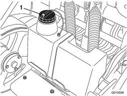
Clean around the air cleaner to prevent dirt from getting into the engine and causing damage.
-
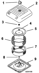
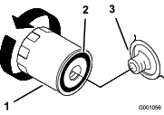
Unscrew the knob and remove the air-cleaner cover (Figure 39).
-
Carefully slide the foam pre-filter off the paper element (Figure 39).
-
Unscrew the cover nut and remove the cover, spacer, and paper filter (Figure 39).
Cleaning the Foam Pre-Filter
Important: Replace the foam element if it is torn or worn.
-
Wash the foam pre-filter in liquid soap and warm water. When clean, rinse it thoroughly.
-
Dry the pre-filter by squeezing it in a clean cloth (do not wring).
-
Put 3 to 6 cl (1 to 2 fl oz) of oil on the pre-filter (Figure 40).
-
Squeeze the pre-filter to distribute the oil.
-
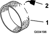
Inspect the paper filter for tears, an oily film, and damage to the rubber seal (Figure 41).
Important: Never clean the paper element. Replace the paper element if it is dirty or damaged.
Installing the Filters
Important: To prevent engine damage, always operate the engine with the complete foam and paper air cleaner assembly installed.
-
Carefully slide the foam pre-filter onto the paper filter (Figure 41).
-
Place the air cleaner assembly onto the air cleaner base (Figure 39).
-
Install the cover, spacer and secure it with the cover nut (Figure 39). Torque the nut to 11 N∙m (95 in-lb).
-
Install the air cleaner cover and secure with the knob (Figure 39).
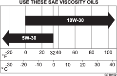
Engine Oil Specification
Oil Type: High-quality, detergent engine oil (API service SJ or higher)
Viscosity: See table below
Checking the Engine-Oil Level
| Maintenance Service Interval | Maintenance Procedure |
|---|---|
| Before each use or daily |
|
The engine is shipped with oil in the crankcase; however, check the oil level before and after the engine is first started.
Use high-quality engine oil as described in Engine Oil Specification.
Important: Do not overfill the crankcase with oil because this may cause engine damage.Do not run the engine with oil below the low mark because the engine may be damaged as a result.
Note: The best time to check the engine oil is when the engine is cool before it has been started for the day. If it has already been run, allow the oil to drain back down to the sump for at least 10 minutes before checking.
-
Park the machine on a level surface, shut off the engine, engage the parking brake, and remove the key.
-
Clean around the oil dipstick (Figure 43) so dirt cannot fall into the filler hole and damage the engine.
-
Remove the dipstick, wipe it clean, and install until it is fully seated (Figure 43).
-
Remove the dipstick and check the oil level.
The oil level should be between the ‘‘F’’ full and ‘‘L’’ low marks on the dipstick (Figure 43).
-
If the oil level is below the ‘‘L’’ low mark, remove the filler tube cap (Figure 43) and add the specified oil until the level reaches the ‘‘F’’ full mark on the dipstick.
-
Install the oil fill cap and dipstick.
Changing the Engine Oil and Filter
| Maintenance Service Interval | Maintenance Procedure |
|---|---|
| After the first 50 hours |
|
| Every 100 hours |
|
Crankcase capacity: approximately 1.9 L (2.0 US qt) with the filter.
-
Start the engine and let it run for 5 minutes. This warms the oil so that it drains better.
-
Park the machine so that the drain side is slightly lower than the opposite side to ensure that the oil drains completely, shut off the engine, engage the parking brake, and remove the key.
-
Place a pan below the oil drain. Remove the oil drain plug to allow oil to drain.
-
When the oil has drained completely, replace the plug.
Note: Dispose of the used oil at a certified recycling center.
-
Place a shallow pan or rag under the filter to catch oil (Figure 44).
-
Remove the old filter (Figure 44 and Figure 45) and wipe the surface of the filter adapter gasket.
-
Pour new oil of the proper type through the center hole of the filter. Stop pouring when the oil reaches the bottom of the threads.
-
Allow a minute or 2 for the oil to be absorbed by filter material, then pour off the excess oil.
-
Apply a thin coat of new oil to the rubber gasket on the replacement filter.
-
Install the replacement oil filter to the filter adapter. Turn the oil filter clockwise until the rubber gasket contacts the filter adapter, then tighten the filter an additional 1/2 turn.
-
Remove the oil fill cap and slowly pour approximately 80% of the specified amount of oil in through the valve cover.
-
Check the oil level; refer to Checking the Engine-Oil Level.
-
Slowly add additional oil to bring the level to the F (full) mark on the dipstick.
-
Install the oil fill cap and dipstick.
Servicing the Spark Plugs
| Maintenance Service Interval | Maintenance Procedure |
|---|---|
| Every 200 hours |
|
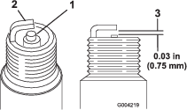
Ensure that the air gap between the center and side electrodes is correct before installing each spark plug. Use a spark-plug wrench for removing and installing the spark plugs and a gapping tool/feeler gauge to check and adjust the air gap. Install new spark plugs if necessary.
Type: Champion RC12YC or equivalent. Air Gap: 0.75 mm (0.03 inch)
Removing the Spark Plugs
-
Shut off the engine, engage the parking brake, and remove the key.
-
Pull the wires off the spark plugs (Figure 46).
-
Clean around the spark plugs.
-
Remove both spark plugs and metal gaskets.
Checking the Spark Plugs
-
Look at the center of both spark plugs (Figure 47). If you see light brown or gray on the insulator, the engine is operating properly. A black coating on the insulator usually means the air cleaner is dirty.
Important: Never clean the spark plugs. Always replace the spark plugs when they have a black coating, worn electrodes, an oily film, or cracks.
-
Check the gap between the center and side electrodes (Figure 47).
-
Bend the side electrode (Figure 47) if the gap is not correct.
Installing the Spark Plugs
-
Thread the spark plugs into the spark plug holes.
-
Tighten the spark plugs to 27 N∙m (20 ft-lb).
-
Push the wires onto the spark plugs (Figure 46).
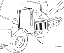
Cleaning the Engine Screen
| Maintenance Service Interval | Maintenance Procedure |
|---|---|
| Before each use or daily |
|
Before each use, check and clean the engine screen. Remove any buildup of grass, dirt, or other debris from the engine air intake screen.
Fuel System Maintenance
Danger
Under certain conditions, fuel and fuel vapors are highly flammable and explosive. A fire or explosion from fuel can burn you and others and can cause property damage.
-
Fill the fuel tank outdoors, in an open area, when the engine is off and is cold. Wipe up any fuel that spills.
-
Do not fill the fuel tank completely full. Add fuel to the fuel tank until the level is 25 mm (1 inch) below the top of the tank, not the filler neck. This empty space in the tank allows the fuel to expand.
-
Never smoke when handling fuel, and stay away from an open flame or where a spark may ignite fuel fumes.
-
Store fuel in a clean, safety-approved container and keep the cap in place.
Replacing the Fuel Filter
| Maintenance Service Interval | Maintenance Procedure |
|---|---|
| Every 100 hours |
|
Important: Never install a dirty filter if it is removed from the fuel line.
-
Allow the machine to cool down.
-
Close the fuel-shutoff valve (Figure 48).
-
Squeeze the ends of the hose clamps together and slide them away from the filter (Figure 48).
-
Remove the filter from the fuel lines.
-
Install a new filter and move the hose clamps close to the filter (Figure 48).
-
Wipe up any spilled fuel.
-
Open the fuel-shutoff valve (Figure 48).
Draining the Fuel Tank
Danger
In certain conditions, fuel is extremely flammable and highly explosive. A fire or explosion from fuel can burn you and others and can damage property.
-
Drain fuel from the fuel tank when the engine is cold. Do this outdoors in an open area. Wipe up any fuel that spills.
-
Never smoke when draining fuel, and stay away from an open flame or where a spark may ignite the fuel fumes.
-
Park the machine on a level surface, shut off the engine, engage the parking brake, and remove the key.
-
Close the fuel-shutoff valve (Figure 48).
-
Loosen the hose clamp at the fuel filter and slide it up the fuel line away from the fuel filter (Figure 48).
-
Pull the fuel line off the fuel filter (Figure 48). Open the fuel-shutoff valve and allow fuel to drain into a fuel can or drain pan.
Note: Now is the best time to install a new fuel filter because the fuel tank is empty.
-
Install the fuel line onto the fuel filter. Slide the hose clamp close to the fuel filter to secure the fuel line (Figure 48).
Electrical System Maintenance
Electrical System Safety
-
Disconnect the battery before repairing the machine. Disconnect the negative terminal first and the positive last. Connect the positive terminal first and the negative last.
-
Charge the battery in an open, well-ventilated area, away from sparks and flames. Unplug the charger before connecting or disconnecting the battery.
-
Wear protective clothing and use insulated tools.
Warning
Battery posts, terminals, and related accessories contain lead and lead compounds, chemicals known to the State of California to cause cancer and reproductive harm. Wash hands after handling.
Charging the Battery
Warning
Charging the battery produces gasses that can explode.
Never smoke near the battery and keep sparks and flames away from the battery.
Warning
Battery terminals or metal tools could short against metal components of the traction unit or machine, causing sparks. Sparks can cause the battery gasses to explode, resulting in personal injury.
-
When removing or installing the battery, do not allow the battery terminals to touch any metal parts of the machine.
-
Do not allow metal tools to short between the battery terminals and any metal parts.
Warning
Incorrect battery cable routing could damage the machine and cables, causing sparks. Sparks can cause the battery gasses to explode, resulting in personal injury.
-
Always disconnect the negative (black) battery cable before disconnecting the positive (red) cable.
-
Always connect the positive (red) battery cable before connecting the negative (black) cable.
-
Unlatch and open the battery compartment cover.
-
Remove the battery from the battery compartment:
-
Remove the battery hold down and hold down rods that secure the battery to the tray (Figure 49).
-
Remove the carriage bolt and nut that secure the negative battery cable (black) to the negative (–) terminal and disconnect the negative cable.
-
Remove the carriage bolt and nut that secure the positive battery cable (red) to the positive (+) battery terminal and disconnect the positive cable.
-
-
Clean the top of the battery.
-
Connect a 3 to 4 A battery charger to the battery posts. Charge the battery at a rate of 3 to 4 A for 4 to 8 hours.
-
When the battery is charged, disconnect the charger from the electrical outlet and battery posts.
-
Insert the battery into the tray in the battery compartment as shown in Figure 49.
-
Connect the positive battery cable (red) to the positive (+) battery terminal with the previously removed carriage bolt and nut; slide the rubber boot over the positive terminal to prevent a possible short from occurring.
-
Connect the negative battery cable (black) to the negative (–) terminal with the previously removed carriage bolt and nut.
-
Coat the cable terminals and battery posts with Grafo 112X skin-over grease (Toro Part No. 505-47).
-
Close and latch the battery compartment cover.
Servicing the Battery
| Maintenance Service Interval | Maintenance Procedure |
|---|---|
| Yearly |
|
The battery cables must be tight on the terminals to provide good electrical contact.
Warning
Incorrect battery cable routing could damage the machine and cables, causing sparks. Sparks can cause the battery gasses to explode, resulting in personal injury.
-
Always disconnect the negative (black) battery cable before disconnecting the positive (red) cable.
-
Always connect the positive (red) battery cable before connecting the negative (black) cable.
If corrosion occurs at the terminals, disconnect the cables (negative (–) cable first) and scrape clamps and terminals separately. Connect the cables (positive (+) cable first) and coat the terminals with petroleum jelly.
Warning
Battery terminals or metal tools could short against metal tractor components, causing sparks. Sparks can cause the battery gasses to explode, resulting in personal injury.
-
When removing or installing the battery, do not allow the battery terminals to touch any metal parts of the machine.
-
Do not allow metal tools to short between the battery terminals and metal parts of the machine.
-
Unlatch and open the battery compartment cover (Figure 50).
-
Check that the battery-cable clamps are secure and tighten any loose battery-cable clamps hardware.
Important: Ensure that there is clearance between the battery cables and the speed selector lever. Verify that the speed selector lever does not come within 1 inch (2.5 cm) of either battery cable when it is moved through its entire range of motion. Do not wire tie or tape the negative and positive battery cables together.
-
Check the battery-cable clamps and battery terminals for corrosion; If the terminals are corroded, do the following:
-
Remove the carriage bolt and nut that secure the negative battery cable (black) to the negative (–) terminal and disconnect the negative cable.
-
Remove the carriage bolt and nut that secure the positive battery cable (red) to the positive (+) battery terminal and disconnect the positive cable.
-
Clean the cable clamps and battery terminals.
-
Connect the positive battery cable (red) to the positive (+) battery terminal with the previously removed carriage bolt and nut; slide the rubber boot over the positive terminal to prevent a possible short from occurring.
-
Connect the negative battery cable (black) to the negative (–) terminal of the battery with the previously removed carriage bolt and nut.
-
Coat the cable terminals and battery posts with Grafo 112X skin-over grease (Toro Part No. 505-47).
-
-
Close and latch the battery compartment cover.
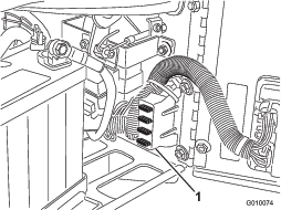
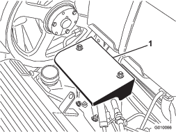
Checking the Fuses
The electrical system is protected by fuses (Figure 51). It requires no maintenance; however, if a fuse blows, check the component/circuit for a malfunction or short.
-
To replace fuses, pull out on the fuse to remove it.
-
Install a new fuse.
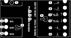
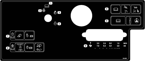
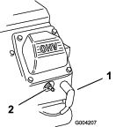
Aerator Control Module (ACM)
The Aerator Control Module is a potted electronic device produced in a 1-size-fits-all configuration. The module uses solid-state and mechanical components to monitor and control electrical features required for safe product operation.
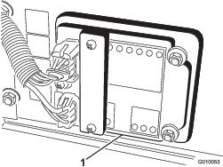
The module monitors inputs including head low, head high, transport, aerate, and ground following. The module is divided into inputs and outputs. Inputs and outputs are identified by green LED indicators mounted on the printed circuit board. Power is identified by a red LED indicator.
The start circuit input is energized by 12 VDC. All other inputs are energized when the circuit is closed to ground. Each input has an LED that illuminates when the specific circuit is energized. Use the input LEDs for switch and input circuit troubleshooting.
Output circuits are energized by an appropriate set of input conditions. The 3 outputs include SVL, SVR, and SVQ. Output LEDs monitor relay conditions indicating the presence of voltage at 1 of 3 specific output terminals.
Output circuits do not determine output device integrity, so electrical troubleshooting includes output LED inspection and conventional device and wire harness integrity testing. Measure the impedance of disconnected components, the impedance through the wire harness (disconnected at the ACM), or by temporarily test energizing the specific component.
The ACM does not connect to an external computer or handheld device, cannot be reprogrammed, and does not record intermittent fault troubleshooting data.
The decal on the ACM includes only symbols. The 3 LED output symbols are shown in the output box. All other LEDs are inputs. The chart below identifies the symbols.
The following are logical troubleshooting steps for the ACM device:
-
Determine the output fault you are trying to resolve.
-
Move the key switch to the ON position and ensure that the red power LED illuminates.
-
Move all input switches to ensure that all LEDs change state.
-
Position input devices at the appropriate position to achieve the appropriate output.
-
If specific output LED illuminates without appropriate output function, check output harness, connections, and component. Repair as required.
-
If specific output LED does not illuminate, check both fuses.
-
If specific output LED does not illuminate and inputs are in appropriate condition, install new ACM and determine if a fault disappears.
Drive System Maintenance
Checking the Tire Pressure
| Maintenance Service Interval | Maintenance Procedure |
|---|---|
| Every 50 hours |
|
Park the machine on a level surface, shut off the engine, engage the parking brake, and remove the key.
Check to ensure that the air pressure in all tires is 83 kPa (12 psi). Check the tires when they are cold to get the most accurate pressure reading.
Important: Uneven tire pressure can cause uneven coring depth.
Caution
The wheel weight is very heavy, 33 kg (73 lb).
Use caution when removing it from the tire assembly.
Adjusting the Traction Drive for Neutral
The machine must not creep when you release the traction bail. If it does, an adjustment is required.
-
Park the machine on a level surface, shut off the engine, engage the parking brake, and remove the key.
-
Raise the machine so the front wheel and 1 rear wheel is just off the ground. Place jack stands under machine. Refer to Raising the Machine.
-
Loosen the locknut on the traction adjustment cam (Figure 55).
-
Start engine and disengage the parking brake.
Warning
The engine must be running so that you can make the final adjustment on the traction adjustment cam. This could cause personal injury.
Keep your hands, feet, face, and other body parts away from the muffler, other hot parts of the engine and any rotating parts.
-
Rotate the cam hex in either direction until the wheels do not rotate.
-
Tighten the locknut securing the adjustment.
-
Shut off the engine.
-
Remove the jack stands and lower the machine to the ground.
-
Test the machine to make sure that it does not creep.
Belt Maintenance
Adjusting the Pump Belt
| Maintenance Service Interval | Maintenance Procedure |
|---|---|
| After the first 8 hours |
|
-
Park the machine on a level surface, shut off the engine, engage the parking brake, and remove the key.
-
Unlatch and remove the belt cover (Figure 56).
-
Remove the 2 pump shield mounting nuts and remove the shield (Figure 57).
-
Loosen the pump belt idler bolt just enough to allow movement within the adjustment slot (Figure 58).
-
Tap the top of the idler pulley and allow the tensioning spring to adjust the belt tension.
Note: Do not apply more belt tension than the tensioning spring allows as damage to the components may result.
-
Secure the belt idler bolt.
-
Install the pump shield and belt cover.
Inspecting the Belts
| Maintenance Service Interval | Maintenance Procedure |
|---|---|
| Yearly |
|
The drive belts on the machine is durable. However, the normal exposure to UV radiation, ozone, or incidental exposure to chemicals can deteriorate the rubber over time and lead to premature wear or material loss (i.e., chunking).
Inspect the belts yearly for signs of wear, excessive cushion cracks, or large embedded debris. Replace them when needed. A complete belt service kit is available from your authorized Toro distributor.
Controls System Maintenance
Resetting the Ground Following System
If the True Core ground following system requires service of any kind (except for replacing the turf guard) or if the tine holders are contacting the turf guards when set in the deepest setting, you may need to reset the depth adjustment tie rod.
-
Park the machine on a level surface, shut off the engine, engage the parking brake, and remove the key.
-
Rotate the left turf guard mounting bracket (Figure 59) up until you can insert a locking pin, such as an 8 mm (5/16 inch) drill rod or bolt, between the bracket and the depth setting tube welded to the frame.
-
Move the tine depth lever (Figure 59) to the H setting (deepest).
-
Disconnect the outboard ball switch (Figure 59) from the wire harness (Head–Low switch).
-
Loosen the jam nuts (left and right) on the depth adjustment tie rod (Figure 59).
-
Use a multi-meter to determine the electrical closure of the ball switch.
-
Rotate the tie rod until the ball switch just closes or makes contact.
-
Secure the left and right jam nuts on the tie rod.
-
Connect the ball switch to the wire harness.
-
Remove the pin from the turf guard bracket and depth setting tube.
Hydraulic System Maintenance
Hydraulic System Safety
-
Seek immediate medical attention if fluid is injected into skin. Injected fluid must be surgically removed within a few hours by a doctor.
-
Ensure that all hydraulic-fluid hoses and lines are in good condition and all hydraulic connections and fittings are tight before applying pressure to the hydraulic system.
-
Keep your body and hands away from pinhole leaks or nozzles that eject high-pressure hydraulic fluid.
-
Use cardboard or paper to find hydraulic leaks.
-
Safely relieve all pressure in the hydraulic system before performing any work on the hydraulic system.
Checking the Hydraulic Lines
| Maintenance Service Interval | Maintenance Procedure |
|---|---|
| Before each use or daily |
|
Before each use, check the hydraulic lines and hoses for leaks, loose fittings, kinked lines, loose mounting supports, wear, weather and chemical deterioration. Make necessary repairs before operating.
Note: Keep the areas around the hydraulic system clean from debris buildup.
Hydraulic Fluid Specification
| Toro Premium Transmission/Hydraulic Tractor Fluid (Available in 5 gallon pails or 55 gallon drums. See parts catalog or Toro distributor for part numbers.) |
Alternative fluids: If the specified fluid is not available, you may use other universal tractor hydraulic fluids (UTHF), but use only conventional, petroleum-based products, not synthetics or biodegradable fluids. The specifications must fall within the listed range for all the following material properties and the fluid should meet listed industry standards. Check with your fluid supplier to see if the fluid meets these specifications.
Note: Toro assumes no responsibility for damage caused by improper hydraulic fluid substitution, so use only products from reputable manufacturers who stand behind their recommendation.
| Material Properties: | |
| Viscosity, ASTM D445 | cSt @ 40°C (104°F) 55 to 62 |
| Viscosity Index ASTM D2270 | 140 to 152 |
| Pour Point, ASTM D97 | -37°C to -43°C (-35°F to -46°F) |
| Industry Specifications: API GL-4, AGCO Powerfluid 821 XL, Ford New Holland FNHA-2-C-201.00, Kubota UDT, John Deere J20C, Vickers 35VQ25, and Volvo WB-101/BM | |
Note: Many hydraulic fluids are almost colorless, making it difficult to spot leaks. A red dye additive for the hydraulic fluid is available in 20 ml (0.67 fl oz) bottles. One bottle is enough for 15 to 22 L (4 to 6 US gallons) of hydraulic fluid. Order part number 44-2500 from your authorized Toro distributor.
Checking the Hydraulic-Fluid Level
| Maintenance Service Interval | Maintenance Procedure |
|---|---|
| Before each use or daily |
|
Important: Check the level of the hydraulic fluid before the engine is first started and daily thereafter
The hydraulic reservoir is filled at the factory with high-quality hydraulic fluid.
-
Park the machine on a level surface, shut off the engine, engage the parking brake, and remove the key.
-
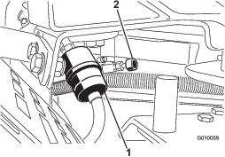
Unlatch and remove the belt cover (Figure 60).
-
Clean the area around the filler neck and the cap of the hydraulic tank (Figure 61). Remove the cap from the filler neck.
-
Remove the dipstick from the filler neck and wipe it with a clean rag. Insert the dipstick into the filler neck; then remove it and check the level of the fluid. The fluid level should be up to the mark on the dipstick (Figure 62).
-
If the level is low, add the specified hydraulic fluid to raise the level to the full mark.
-
Install the dipstick and cap onto the filler neck.
Changing the Hydraulic Fluid and Filters
| Maintenance Service Interval | Maintenance Procedure |
|---|---|
| After the first 8 hours |
|
| Every 200 hours |
|
Hydraulic reservoir capacity: approximately 6.6 L (1.75 US gallons)
Important: Do not substitute automotive oil filters or severe hydraulic system damage may result.
Note: Removing the return filter drains the entire fluid reservoir.
-
Park the machine on a level surface, shut off the engine, engage the parking brake, and remove the key.
-
Place a drain pan under the filters, remove the old filters, and wipe the filter adapter gasket surface clean (Figure 63).
-
Apply a thin coat of hydraulic fluid to the rubber gasket on the replacement filters.
-
Install the replacement hydraulic filters onto the filter adapters. Turn each filter clockwise until the rubber gasket contacts the filter adapter, then tighten each an additional 1/2 turn.
-
Add the specified hydraulic fluid until the fluid level is at the Full mark on the dipstick, refer to Checking the Hydraulic-Fluid Level.
-
Start the engine and let it run for about 2 minutes to purge air from the system. Shut off the engine and remove the key, and check for leaks.
-
Check the fluid level again while the fluid is warm. Add the specified hydraulic fluid to raise the level to the Full mark on the dipstick, if required.
Note: Do not overfill the hydraulic reservoir with fluid.
Hydraulic System Test Ports
The test ports are used to test the pressure in the hydraulic circuits. Contact your authorized Toro distributor for assistance.
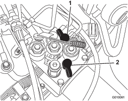
Aerator Maintenance
Checking the Fastener Torque
| Maintenance Service Interval | Maintenance Procedure |
|---|---|
| After the first 8 hours |
|
Park the machine on a level surface, shut off the engine, engage the parking brake, and remove the key.
Check the coring head fasteners, tiller handle fasteners, and wheel lug nuts to ensure that the proper torque is maintained. Fastener torque requirements are listed on the reference service decal located on the coring head.
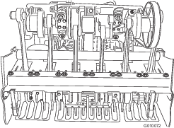
Adjusting the Side Shields
The coring head side shields should be adjusted so the bottom rides between 25 to 38 mm (1 to 1.5 inches) from the turf while aerating.
-
Park the machine on a level surface, shut off the engine, engage the parking brake, and remove the key.
-
Loosen the bolts and nuts securing the side shield to frame (Figure 66).
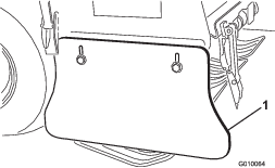
-
Adjust the shield up or down and tighten the nuts.
Replacing the Turf Guards
All turf guards should be replaced if broken or worn to less than 6 mm (1/4 inch) thickness. Broken turf guards can catch and tear turf creating undesirable damage.
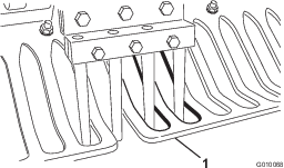
Thin turf guards can cause the True Core ground following system to be off from the desired depth setting due to both wear and the loss of stiffness.
Adjusting Hole Spacing
The hole spacing of the aerator is determined by the ground speed the traction system is set to maintain. The hole spacing is set to within 3 mm (1/8 inch) of the nominal setting at the factory.
In the event the hole spacing is off from the nominal setting more than desired, proceed as follows:
-
Park the machine on a level surface, shut off the engine, engage the parking brake, and remove the key.
-
Unlatch and remove the belt cover (Figure 56).
-
Remove the 2 pump shield mounting nuts and remove the shield (Figure 57).
-
In an open space that is free to aerate (i.e. sample plot), set the aerator spacing lever to the desired hole spacing and make an aeration pass of at least 4.5 m (15 ft).
-
Measure the distance between several holes and divide by the number of holes measured to get your average hole spacing.
Example: Nominal Hole Spacing Setting of 2 inches:
21.2 divided by 10 is 2.12, hole spacing is long by .12 inch from nominal (Figure 68).

18.8 divided by 10 is 1.88, hole spacing is short by 0.12 inch from nominal (Figure 69).

-
If an adjustment is needed, turn the pump stop bolt (Figure 70) closer to the stop plate to decrease hole spacing or turn the stop bolt away from the stop plate to increase hole spacing.
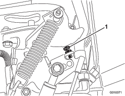
-
Repeat steps 4 through 6 until spacing is at the nominal setting.
Note: One complete turn of the stop bolt adjusts the hole spacing approximately 16 mm (5/8 inch).
Coring Head Timing
The coring head timing marks are easily identified by the marks in the casting.
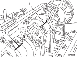
Storage
-
Park the machine on a level surface; engage the parking brake; shut off the engine; remove the key; and wait for all movement to stop before leaving the machine.
-
Disconnect the spark-plug wire.
-
Remove grass, dirt, and grime from the external parts of the entire machine, especially the engine and the hydraulic system. Clean dirt and chaff from the outside of the cylinder-head fins of the engine and blower housing.
-
Service the air cleaner; refer to Servicing the Air Cleaner.
-
Change the crankcase oil; refer to Changing the Engine Oil and Filter.
-
Change the hydraulic filters and fluid, refer to Changing the Hydraulic Fluid and Filters.
-
Check the tire pressure; refer to Checking the Tire Pressure.
-
Check the condition of the tines.
-
If you are storing the machine for more than 30 days, prepare it as follows:
-
Remove the battery cables from the battery posts and remove the battery from the machine.
-
Clean the battery, terminals, and posts with a wire brush and baking soda solution.
-
Coat the cable terminals and battery posts with Grafo 112X skin-over grease (Toro Part No. 505-47) or petroleum jelly to prevent corrosion.
-
Slowly recharge the battery every 60 days for 24 hours to prevent lead sulfation of the battery. To prevent the battery from freezing, make sure it is fully charged. The specific gravity of a fully charged battery is 1.265 to 1.299.
Warning
Charging the battery produces gasses that can explode.
Never smoke near the battery and keep sparks and flames away from it.
-
Either store the battery on the shelf or on the machine. Leave the cables disconnected if it is stored on the machine. Store it in a cool atmosphere to avoid quick deterioration of the charge in the battery.
-
Add a petroleum-based stabilizer/conditioner to fuel in the tank. Follow mixing instructions from stabilizer manufacture. Do not use an alcohol-based stabilizer (ethanol or methanol).
Note: A fuel stabilizer/conditioner is most effective when mixed with fresh fuel and is always used.
-
Run the engine to distribute conditioned fuel through the fuel system for 5 minutes.
-
Shut off the engine, allow it to cool, and drain the fuel tank; refer to Draining the Fuel Tank.
-
Start the engine and run it until it shuts off.
-
Choke the engine. Start and run the engine until it does not start.
-
Dispose of fuel properly. Recycle it according to local codes.
Important: Do not store fuel containing stabilizer/conditioner longer than the duration recommended by the fuel-stabilizer manufacturer.
-
-
Remove the spark plugs and check the condition; refer to Servicing the Spark Plugs. With the spark plugs removed from the engine, pour 2 tablespoons of engine oil into each spark plug hole. Now use the starter to crank the engine and distribute the oil inside the cylinders. Install the spark plugs. Do not install the wires on the spark plugs.
-
Check and tighten all bolts, nuts, and screws. Repair or replace any part that is damaged or worn.
-
Wash and dry the entire machine. Remove the tines, and clean and oil them. Spray light oil mist on coring head bearings (crank and damper links).
Important: You can wash the machine with mild detergent and water. Do not pressure-wash the machine. Avoid excessive use of water, especially near the control panel, engine, hydraulic pumps, and motors.
Note: Run the machine with the engine at high idle for 2 to 5 minutes after washing.
-
Paint all scratched or bare metal surfaces. Paint is available from your authorized Toro distributor.
-
Secure service latch if the machine is to be stored for more than a couple of days.
-
Store the machine in a clean, dry garage or storage area. Remove the key from the ignition switch and keep it out of reach of children or other unauthorized users.
-
Cover the machine to protect it and keep it clean.
Troubleshooting
| Problem | Possible Cause | Corrective Action |
|---|---|---|
| The starter does not crank. |
|
|
| The engine does not start, starts hard, or fails to keep running. |
|
|
| The engine loses power. |
|
|
| The engine overheats. |
|
|
| There is abnormal vibration. |
|
|
| The machine does not drive. |
|
|
| The coring head does not drive. |
|
|
| The head bounces while aerating. |
|
|
| The turf is tufting/tearing on entrance and exit. |
|
|
| There is an issue with quad (or mini) tine hole spacing. |
|
|
| There is hole tufting with side eject tines. |
|
|
| The turf is lifting/tearing while aerating. |
|
|
| The front of the hole is dimpled or pushed. |
|
|