This kit provides improved traction in reverse when traction is reduced in certain ground conditions.
Installation
Preparing to Install the Kit
Washing the Machine
Important: Before installing this kit, you must thoroughly clean the machine to avoid contaminating the hydraulic system—a clean machine is required.
Wash the machine; refer to washing the machine in the Operator’s Manual for your machine.
Preparing the Machine
-
Park the machine on a level surface.
-
Lower the cutting units.
-
Engage the parking brake.
-
Shut off the engine and remove the key.
-
Wait for all moving parts to stop.
-
Allow the engine to cool completely.
Opening the Hood
Unlatch and open the hood.
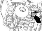
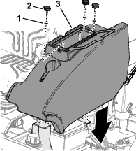
Removing the Storage Compartment
Installing the Rear Traction-Manifold Solenoids
Parts needed for this procedure:
| High-pressure valve | 2 |
| Coil | 2 |
| Nut | 2 |
-
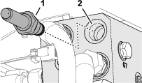
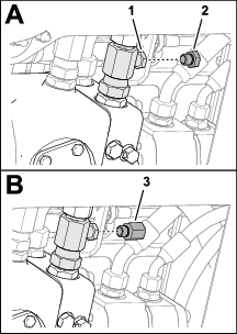
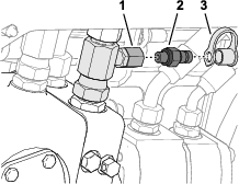
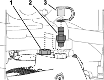
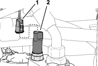
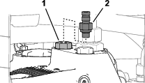
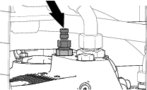
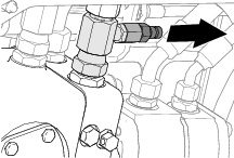
At the back of the machine, remove the check valve from port-CV of the traction manifold (Figure 3).
-
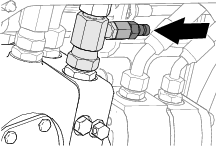
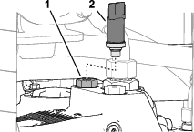
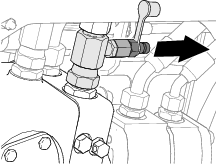
Assemble the high-pressure valve into port-CV (Figure 4).
-
Torque the high-pressure valve to 110 N∙m (81 ft-lb).
-
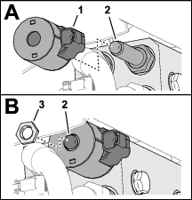
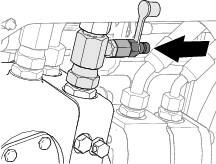
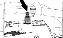
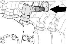
Assemble the coil and nut onto high-pressure valve as shown in Figure 5.
-
Torque the nut to 8 N∙m (6 ft-lb).
-
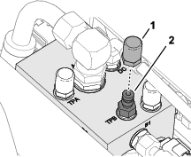
Remove the cap from the 2-socket connector of the machine wire harness labeled REVERSE SOLENOID (Figure 6).
-
Plug the 2-socket connector REVERSE SOLENOID into the 2-pin connector of the coil (Figure 6).
-
Repeat steps 1 through 7 at the other side of the rear traction manifold.
Installing the Quick-Connect Test Fitting
Parts needed for this procedure:
| Adapter fitting (1/4 x 7/16 inch)—Model 31654, and Models 31657 and 31659 with the optional differential-lock kit. | 1 |
| Seal (1/4)—Models 31657 and 31659 with the optional differential-lock kit. | 1 |
| Quick-connect fitting—Model 31654, and Models 31657 and 31659 without the optional differential-lock kit. | 1 |
| Dust cap—machines without the optional road light kit. | 1 |
| Reducer fitting (3/4 x 7/16 inch)—Models 31657 and 31659 without the optional differential-lock kit. | 1 |
Installing the Quick Connect Fitting
-
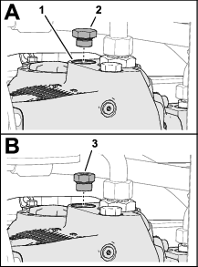
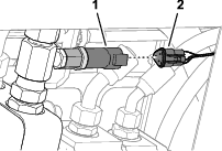
At the right side of the traction pump, remove the plug from the T-fitting in port-B of the traction pump (Figure 7 and Figure 8).
-
Assemble the adapter fitting (1/4 x 7/16 inch) into the T-fitting (Figure 8).
-
Torque the assemble the adapter to 34 to 41 N∙m (25 to 30 ft-lb).
-
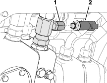
Assemble the quick-connect fitting into the adapter fitting (Figure 9).
-
Torque the quick-connect fitting to 27 N∙m (20 ft-lb).
-
Assemble the retainer of the dust cap onto the quick-connect fitting (Figure 9).
-
You will install the cap over the fitting in Installing the Dust Cap.
Installing the Quick Connect Fitting
-
At the right side of the traction pump, remove the plug from port-MB of the traction pump (Figure 9 and Figure 11).
-
Assemble the reducer fitting (3/4 x 7/16 inch) into port-MB of the traction pump (Figure 11).
-
Torque the reducer fitting to 81 N∙m (60 ft-lb).
-
Assemble the quick-connect fitting into the reducer fitting (Figure 12).
-
Torque the quick-connect fitting to 27 N∙m (20 ft-lb).
-
Assemble the retainer of the dust cap onto the quick-connect fitting (Figure 12).
Note: You will install the cap over the fitting in Installing the Dust Cap.
Preparing to Test the Hydraulic Pressure
Parts needed for this procedure:
| Hydraulic test equipment 260 to 325 bar (3771 to 4714 psi), with a quick-disconnect fitting (facility provided) | . |
Installing the Quick-Connect Fitting
-
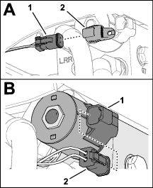
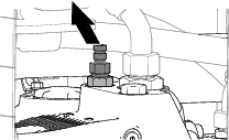
At the right side of the traction pump, remove the 3-pin connector labeled BRAKE PRESSURE SENSOR from the brake-pressure transducer (Figure 13).
-
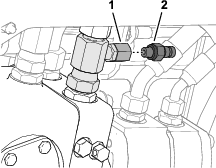
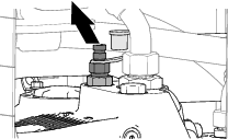
Remove the brake-pressure transducer from the adapter at T-fitting of traction pump port-B (Figure 14).
-
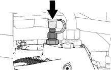
Assemble the quick-connect fitting into the adapter fitting (Figure 15).
-
Torque the quick-connect fitting to 27 N∙m (20 ft-lb).
-
Assemble the test equipment onto the quick-connect fitting (Figure 16).
-
Connect the battery, lower the hood, and perform the hydraulic-pressure test; refer to Connecting the Battery, Closing the Hood, and Testing the Hydraulic Pressure.
Preparing the Traction Pump
-
At the right side of the traction pump, assemble the test equipment onto the quick-connect fitting (Figure 17).
-
Connect the battery, lower the hood, and perform the hydraulic-pressure test; refer to Connecting the Battery, Closing the Hood, and Testing the Hydraulic Pressure.
Preparing to Test the Hydraulic Pressure
Parts needed for this procedure:
| Hydraulic test equipment 260 to 325 bar (3771 to 4714 psi) with a Quick-Connect Fitting (machines without the optional differential-lock kit) or a Minimess™ fitting (machines with the optional differential-lock kit)—facility provided | . |
Installing the Quick-Connect Fitting
-
At the right side of the traction pump, remove the 3-pin connector labeled BRAKE PRESSURE SENSOR from the brake-pressure transducer (Figure 18).
-
Remove the brake-pressure transducer (Figure 19) from the reducer fitting (3/4 x 7/16 inch).
-
Assemble the quick-connect fitting (Figure 20) into the reducer fitting.
-
Torque the quick-connect fitting to 27 N∙m (20 ft-lb).
-
Assemble the test equipment onto the quick-connect fitting (Figure 21).
-
Connect the battery, install the storage compartment, and perform the hydraulic-pressure test; refer to Connecting the Battery, Installing the Storage Compartment, and Testing the Hydraulic Pressure.
Preparing the Traction Pump
-
At the right side of the traction pump, assemble the test equipment onto the quick-connect fitting (Figure 22).
-
Connect the battery, install the storage compartment, and perform the hydraulic-pressure test; refer to Testing the Hydraulic Pressure.
Preparing the Forward Traction Manifold
-
Unlatch and raise the operator’s platform; refer to the Operator’s Manual.
-
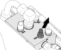
At the front traction manifold, remove the dust cap from the Minimess fitting in port-TPB (Figure 23).
-
Assemble the test equipment onto the Minimess fitting (Figure 24).
Note: Place the test equipment at a location so that you can lower the platform and start the engine.

-
Lower and latch the platform; refer to the Operator’s Manual.
-
Connect the battery, install the storage compartment, and perform the hydraulic-pressure test; refer to Testing the Hydraulic Pressure.
Connecting the Battery and Installing the Storage Compartment
Connecting the Battery
Closing the Hood
Close and latch the hood.
Installing the Storage Compartment
-
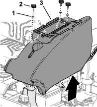
Align the holes on the bottom of the storage compartment with the holes in the chassis brackets.
-
Assemble the storage compartment to the machine with the 3 knobs and 3 washers (Figure 26).
-
Close the storage-compartment door.
Testing the Hydraulic Pressure
-
Start the engine and move the machine to a level, open area.
Important: The area to the rear and around the machine must be clear.
-
Ensure that the parking brake switch is on the ENGAGED position.
-
Set the engine speed to idle.
-
Run the engine to warm the coolant to 70 to 75°C (160 to 170 °F).
-
Sitting in the seat with the park brake engaged, gradually press the reverse traction pedal.
Important: If the reverse pedal is pressed gradually and gently, the park brake should keep the machine from moving backward.
-
Observe the pressure gauge for stable measurement of the maximum hydraulic pressure while pressing the reverse pedal.
-
Record the maximum hydraulic-pressure measurement here: .
-
Compare the maximum hydraulic pressure that you measured with the normal pressure range in the Hydraulic-Pressure Table.
Hydraulic-Pressure Table
Model
Normal Pressure Range
31654
300 to 325 bar (4351 to 4713 psi)
31657 and 31659
260 to 280 bar (3771 to 4061 psi)
Important: If the hydraulic pressure measurements are lower than or higher than the normal pressure range, contact Toro customer care.
-
Shut off the engine, remove the key, and wait for all moving parts to stop before leaving the operator’s position.
Finishing the Hydraulic Test
Installing the Brake-Pressure Transducer
-
Disconnect the test equipment from the quick-connect fitting (Figure 27).
-
Remove the quick-connect fitting from the adapter fitting (Figure 28).
Note: Retain the quick-connect fitting.
-
Assemble the brake-pressure transducer into the adapter fitting (Figure 29).
-
Torque the brake-pressure transducer to 27 N∙m (20 ft-lb).
-
Plug the 3-pin connector of the machine wire harness labeled BRAKE PRESSURE SENSOR into the connector of the pressure transducer (Figure 30).
Finishing the Hydraulic Test
Installing the Brake-Pressure Transducer
-
Disconnect the test equipment from the quick-connect fitting (Figure 33).
-
Remove the quick-connect fitting from the reducer fitting (Figure 34).
Note: Retain the quick-connect fitting.
-
Assemble the brake-pressure transducer (Figure 35) into the reducer fitting (3/4 x 7/16 inch).
-
Torque the transducer to 27 N∙m (20 ft-lb).
-
Plug the 3-pin connector of the machine wire harness labeled BRAKE PRESSURE SENSOR into the connector of the pressure transducer (Figure 36).
Installing the Dust Cap
Installing the Dust Cap
Checking the Hydraulic-Fluid Level
Check the hydraulic fluid level in the tank—add hydraulic fluid as needed; refer to Checking the Hydraulic Fluid in the Operator’s Manual for your machine.