This kit requires the Auxiliary Hydraulic Kit (Model 31966) to be installed on the machine.
Note: Determine the left and right sides of the machine from the normal operating position.
Installation
Warning
Hydraulic fluid escaping under pressure can penetrate skin and cause injury.
-
Seek immediate medical attention if fluid is injected into skin. Injected fluid must be surgically removed within a few hours by a doctor.
-
Ensure that all hydraulic-fluid hoses and lines are in good condition and all hydraulic connections and fittings are tight before applying pressure to the hydraulic system.
-
Keep your body and hands away from pin-hole leaks or nozzles that eject high-pressure hydraulic fluid.
-
Use cardboard or paper to find hydraulic leaks.
-
Safely relieve all pressure in the hydraulic system before performing any work on the hydraulic system.
Preparing the Machine
Preparing the Machine
-
Park the machine on a level surface.
-
Shift to the NEUTRAL position.
-
Lower all attachments (if equipped).
-
Engage the parking brake.
-
Shut off the engine and remove the key.
-
Disconnect the battery; refer to your machine Operator’s Manual.
Installing the Connectors to the Front Hoses
Parts needed for this procedure:
| 90° elbow | 2 |
| Male fitting | 1 |
| Female fitting | 1 |
| Front hoses | 2 |
Removing the Right Wheel and Draining the Hydraulic Tank
-
Raise the right side of the machine off the ground and block up the rear of the machine. Refer to the machine Operator's Manual under Raising the Machine.
Warning
Mechanical or hydraulic jacks may fail to support the machine and cause serious injury.
Use jack stands when supporting the machine.
-
Remove the right tire.
-
Thoroughly clean the area around the hydraulic tank.
-
Drain the hydraulic tank. Refer to the machine Operator's Manual.
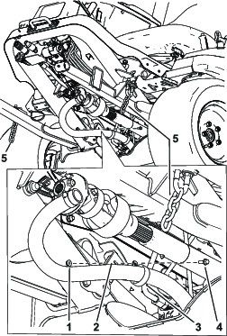
Removing the Hydraulic Tank
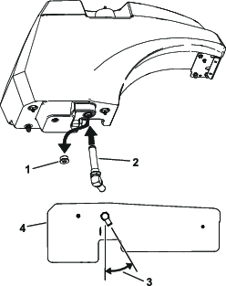
Installing the Fittings to the Hydraulic Tank
Parts needed for this procedure:
| 90° strainer | 1 |
| 45° fitting | 1 |
Note: Make sure that all O-rings are lubricated and properly positioned on all fittings before installation.
Note: Install the fittings at the angles shown in the figures.
Important: Use a backup wrench on all tank fittings when tightening the nuts. When using the 2 wrenches, hold the fitting in place and tighten the nut to the appropriate torque.
-
Remove the tank plug from the side of the tank.
-
Install the 45° fitting into the side to the tank at the angle shown in Figure 5.
-
Torque the fitting to 115.2 N∙m (85 ft-lb).
-
Remove the strainer from the bottom of the hydraulic tank.
-
Remove the tank plug from the bottom of the tank (Figure 6).
-
Install the 90° strainer into the hydraulic tank where the tank plug was removed and at the angle shown in Figure 6.
-
Torque the strainer fitting to 96.2 N∙m (71 ft-lb).
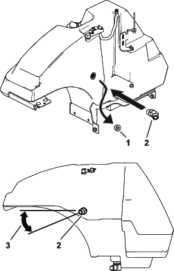
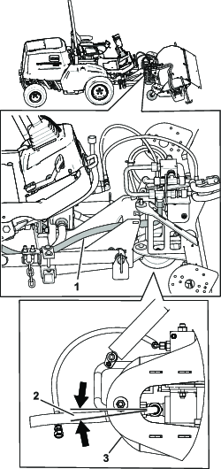
Installing the Hydraulic Tank
-
Install the tank onto the rubber isolators on the machine.
Note: Ensure the tank fits correctly on the rubber isolators.
-
Install the bottom bolt, hose clamp, and hose shown in Figure 7.
-
Torque the hose clamp to 4.5 N∙m (40 in-lb).
-
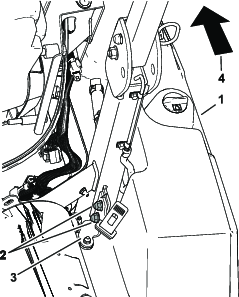
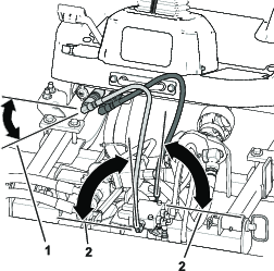
Install the rear tank bracket behind the roll bar using the previously removed bolts. Push down on the bracket while tightening the bolts. Refer to Figure 8.
-
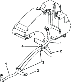
Install the vent hoses shown in Figure 9.
Installing the Broom Attachment
Parts needed for this procedure:
| Broom attachment | 1 |
-
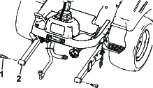
Remove the shoulder bolts from the machine lift arms (Figure 10). Refer to the Service Manual for removing the bolts.
-
Remove the pins and the brackets from the broom frame (Figure 11).
-
Slide the broom attachment under the lift arms.
-
Install the pins into the broom frame and lift arms (Figure 11).
-
Install the brackets to the lift arms.
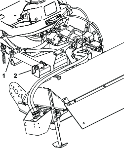
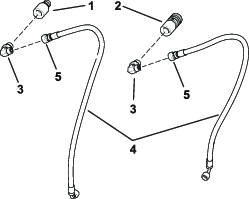
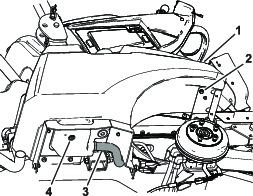
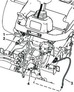
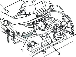
Installing the Front Hoses
Note: Install the hoses at the angles shown in Figure 13.
-
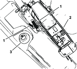
Install the hydraulic hose with the male fitting to the front of the broom manifold (Figure 12). Refer to Figure 13 for the correct angle.
-
Torque the fitting to 27 N∙m (20 ft-lb).
-
Connect the hydraulic hose with the hydraulic port under the steering column (Figure 12).
-
Install the hydraulic hose with the female fitting to the back of the broom manifold (Figure 12). Refer to Figure 13 for the correct angle.
-
Torque the fitting to 27 N∙m (20 ft-lb).
-
Connect the hydraulic hose with the hydraulic port under the steering column (Figure 12).
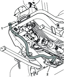
Note: Ensure the hoses are not twisted by adjusting the elbow fittings on the ends of the hoses (Figure 1).
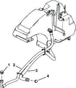
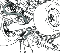
Installing the Hydraulic Hoses to the Tank and Broom
Parts needed for this procedure:
| Strainer hose | 1 |
| Side hydraulic hose | 1 |
| R-clamp | 1 |
| Bolt (1/4 x 3/4 inch) | 1 |
| Flange nut (1/4 inch) | 1 |
| Hose clamp | 2 |
| Cable ties | 6 |
Use Figure 14 for identifying the hoses and the placement of the cable ties.
-
Install the strainer hose to the broom pump (Figure 15).
-
Torque the hose clamp to 4.5 N∙m (40 in-lb).
-
Install the R-clamp onto the hose.
-
Install the strainer hose to the strainer fitting on the bottom of the hydraulic tank (Figure 16).
-
Torque the hose clamp to 4.5 N∙m (40 in-lb).
-
Install the R-clamp to the machine bracket with a bolt (1/4 x 3/4 inch) and flange nut (1/4 inch); refer to (Figure 17).
-
Install the side hydraulic hose to the broom (Figure 18).
-
Torque the fitting to 122 N∙m (90 ft-lb).
Note: Install the hose at the angle shown in Figure 18.
-
Install the side hydraulic hose to the hydraulic tank (Figure 19).
-
Torque the fitting to 122 N∙m (90 ft-lb).
-
Install the cable ties at the positions shown in Figure 14.
-
Use cable ties to secure the chains to the U-bolts (Figure 17).
Tightening All Connections
Important: Make sure that the hoses and hydraulic lines are routed away from and to do not rub against any sharp, hot, or moving components.
When all hydraulic lines and hoses are installed, check and tighten all of the connections.
Important: Use a backup wrench on all tank fittings when tightening the nuts. When using the 2 wrenches, hold the fitting in place and tighten the nut to the appropriate torque.
Installing the Hydraulic Fluid and Checking for Leaks
The hydraulic system capacity is 45 L (12 US gallons).
Refer to the Operator's Manual for the correct fluid to use.
-
Fill hydraulic fluid into the tank to the upper mark on the dipstick. Refer to Hydraulic System Maintenance in the Operator’s Manual.
-
Connect the battery; refer to your machine Operator’s Manual.
-
Start the machine and let it run for 5 minutes.
-
Check the hoses and tank for any leaks.
-
Install the front tire.
-
Lower the machine onto the ground.
Installing the Plugs
Parts needed for this procedure:
| Plastic plug | 1 |
| Metal plug | 1 |
-
When you remove the broom, install the metal plug into the end of the side hydraulic hose and the plastic plug into the strainer hose. Refer to Figure 20.
-
Torque the metal plug to 122 N∙m (90 ft-lb).
-
Torque the hose clamp for the plastic plug to 4.5 N∙m (40 in-lb).
-
Secure the hoses to the machine away from sharp edges, moving parts, and hot surfaces.