
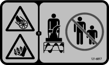
 , which means Caution, Warning,
or Danger—personal safety instruction. Failure to comply with
these instructions may result in personal injury or death.
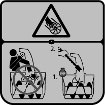
, which means Caution, Warning,
or Danger—personal safety instruction. Failure to comply with
these instructions may result in personal injury or death.

Maintenance
Caution
If you leave the key in the switch, someone could accidently start the engine and seriously injure you or other bystanders.
Shut off the engine and remove the key from the switch before you perform any maintenance.
Maintenance Safety
Read the following safety precautions before performing any maintenance on the machine:
-
Before servicing, adjusting, or cleaning the machine, shut off the engine and remove the key.
-
Always wear eye protection while performing an adjustment or repair to protect your eyes from foreign objects that the machine may throw.
-
Check all fasteners at frequent intervals for proper tightness to ensure that the machine is in safe working condition.
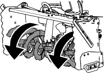
Adjusting the Skids
| Maintenance Service Interval | Maintenance Procedure |
|---|---|
| Every 50 hours |
|
Check the skids to ensure that the auger does not contact the paved or gravel surface. Adjust the skids as needed to compensate for wear.
-
Park the machine on a level surface, disengage the PTO, and engage the parking brake.
-
Shut off the engine, remove the key, and wait for all moving parts to stop before leaving the operating position.
-
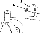
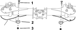
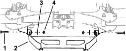
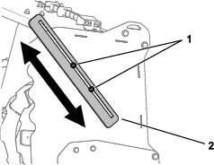
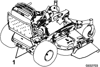
Loosen the nuts that secure both skids to the auger sides until the skids slide up and down easily (Figure 28).
Important: Support the auger blades above the ground using the skids.
-
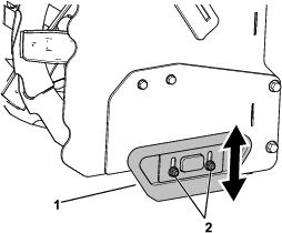
Move the skids down until they are even with the ground.
-
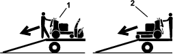
Ensure that the trip edges are 3 mm (1/8 inch) above and parallel to a level surface (Figure 30).
Note: If the pavement is cracked, rough, or uneven, adjust the skids to raise the trip edges. For gravel surfaces, adjust the skids further down to prevent the machine from picking up rocks.
-
Firmly tighten the nuts that secure both skids to the auger sides.
Note: To quickly adjust the skids if they loosen, support the trip edges 3 mm (1/8 inch) off the pavement, then adjust the skids down to the pavement
-
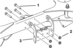
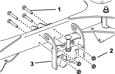
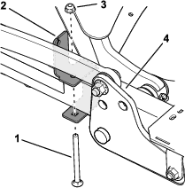
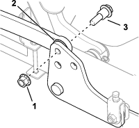
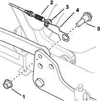
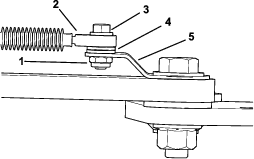
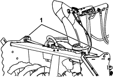
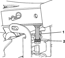
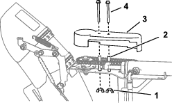
Adjust the stop bolt as follows:
-
Support the A-frame using blocks or a cylinder lock.
-
Loosen the jam nut.
-
Adjust the stop bolt until it contacts the A-frame.
Note: This prevents the hydraulics from applying force on the skids and reduces wear.
-
Replacing the Trip Edges
| Maintenance Service Interval | Maintenance Procedure |
|---|---|
| Every 50 hours |
|
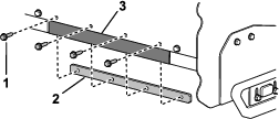
Replace the trip edges when they are worn.
Note: Operating conditions affects trip-edge wear. Operating the snowthrower on dry pavement will cause the trip edges to wear faster than operating it on wet snow.
-
Park the machine on a level surface, disengage the PTO, and engage the parking brake.
-
Shut off the engine, remove the key, and wait for all moving parts to stop before leaving the operating position.
-
Remove the bolts and retainer plate.
-
Remove the trip edge and install a new one using the retainer plate and fasteners.
Checking the Auger-Gearbox-Oil Level
| Maintenance Service Interval | Maintenance Procedure |
|---|---|
| Yearly |
|
-
Park the machine on a level surface, disengage the PTO, and engage the parking brake.
-
Shut off the engine, remove the key, and wait for all moving parts to stop before leaving the operating position.
-
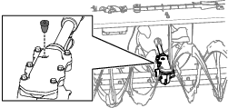
Clean the area around the pipe plug and remove the pipe plug from the gearbox.
Note: If needed, use pliers to assist in removing the pipe plug.
-
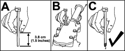
Check the oil level using a suitable measuring device, such as a clean cable tie. The oil should be approximately 3.8 cm (1.5 inches) below the filler opening
-
If the oil level is low, add SAE 80W-140 gear oil lubricant to the gearbox, then check the oil level again.
Note: Do not use synthetic oil.
-
Install the pipe plug in the gearbox.
Checking the Belt
| Maintenance Service Interval | Maintenance Procedure |
|---|---|
| Every 150 hours |
|
Check belt for cracks, frayed edges, burn marks, wear, signs of overheating, or any other damage.
The signs of a worn belt are squealing while the belt is rotating, cracks, cuts or gouges. Replace the belt if you detect any of these signs.
Replacing the Belt
-
Park the machine on a level surface, disengage the PTO, and engage the parking brake.
-
Shut off the engine, remove the key, and wait for all moving parts to stop before leaving the operating position.
-
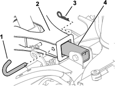
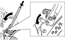
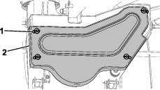
Remove the 4 hairpin cotters securing the belt cover (Figure 33).
-
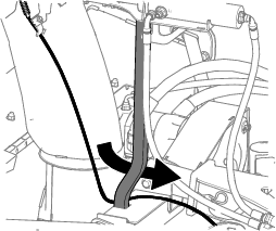
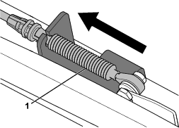
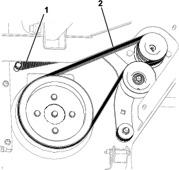
Remove the belt from the pulleys (Figure 34).
Warning
The spring is under tension when installed and can cause personal injury.
Be careful when removing the belt.
-
Wrap the new belt around the small pulley (Figure 34).
-
Rotate the large pulley by hand and wrap the belt around it as it rotates (Figure 34).
Note: The tension on the spring will increase as you rotate the belt on the pulley.
-
Install the belt cover and secure it using the 4 hairpin cotters (Figure 33).
Adjusting the Drive Chain
-
Park the machine on a level surface, disengage the PTO, and engage the parking brake.
-
Shut off the engine, remove the key, and wait for all moving parts to stop before leaving the operating position.
-
Remove the drive-chain cover.
-
Loosen the nut.
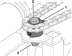
-
Using a closed-end wrench, pull the nut to apply tension to the chain, and tighten the bolt using a socket wrench.
Note: Ensure that the chain is tight but does not bind.
Important: If you remove the shoulder bolt, apply anti-seize compound to the bolt before installing it.
-
Tighten the nut.
-
Install the cover as shown in Figure 35.