Installation
Preparing the Machine
-
Park the machine on a level surface.
-
Move the motion-control levers to the NEUTRAL-LOCK position.
-
Engage the parking brake.
-
Lower the mower deck to the lowest height of cut.
-
Shut off the engine and remove the key.
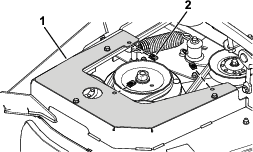
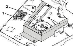
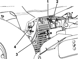
Removing the Belt Covers
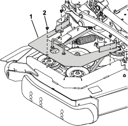
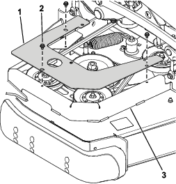
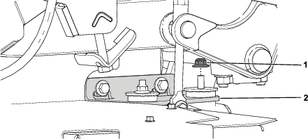
Remove the belt covers (Figure 1).
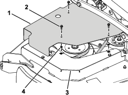
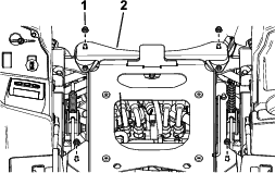
Removing the Reverse-Drive Cover
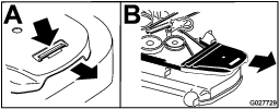
Remove the 3 self-tapping screws securing the reverse-drive cover and remove the cover from the right side of the mower deck (Figure 2).
Retain the 3 self-tapping screws for installation in Installing the Right Pulley-Mount Guard and Pulley Guard.
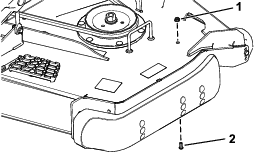
Installing the Right Pulley-Mount Guard and Pulley Guard
Parts needed for this procedure:
| Right pulley-mount guard | 1 |
| Right pulley guard | 1 |
| Clip | 3 |
| Push nut | 3 |
| Flange-head bolt (1/4 x 3/4 inch) | 3 |
-
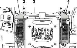
Secure the right pulley-mount guard to the belt guard using the previously removed 3 self-tapping screws (Figure 3).
-
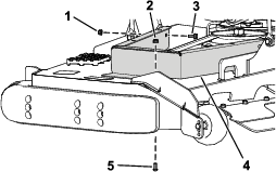
Install 3 clips on to the right pulley-mount guard (Figure 4).
-
Secure the right pulley guard to the right pulley-mount guard using 3 flange-head bolts (1/4 x 3/4 inch) and 3 push nuts (Figure 5).
Installing the Left Pulley-Mount Guard and Pulley Guard
Parts needed for this procedure:
| Left pulley-mount guard | 1 |
| Left pulley guard | 1 |
| Clip | 4 |
| Push nut | 4 |
| Flange-head bolt (1/4 x 3/4 inch) | 4 |
| Flange-head bolt (5/16 x 3/4 inch) | 1 |
| Flange nut (5/16 inch) | 1 |
-
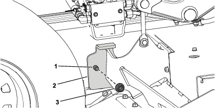
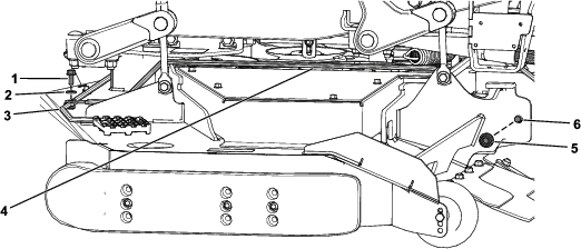
Remove the button-head bolt (5/16 x 3/4 inch) and flange nut (5/16 inch) from the left side of the mower deck (Figure 6).
Retain the button-head bolt (5/16 x 3/4 inch) and flange nut (5/16 inch).
Note: Raise the mower deck to assist with installing the button-head bolt (5/16 x 3/4 inch) and flange nut (5/16 inch) in the next step.
-
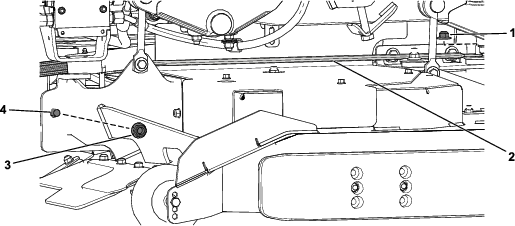
Secure the left pulley-mount guard to the mower deck using the previously removed button-head bolt (5/16 x 3/4 inch) and flange nut (5/16 inch) and new flange-head bolt (5/16 x 3/4 inch) and flange nut (5/16 inch) as shown in Figure 7.
-
Install 4 clips on to the left pulley-mount guard (Figure 8).
-
Secure the left pulley guard to the left pulley-mount guard using 4 flange-head bolts (1/4 x 3/4 inch) and 4 push nuts (Figure 9).
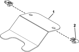
Installing the Brace Bracket
Parts needed for this procedure:
| Brace bracket | 1 |
Installing the Support Rods to the Skirt Guard Assembly
Parts needed for this procedure:
| Skirt guard assembly | 1 |
| Front, upper support rod | 1 |
| Front, lower support rod | 1 |
| Left, upper support rod | 1 |
| Right, upper support rod | 1 |
| Left, lower support rod | 1 |
| Right, lower support rod | 1 |
| Flange nut (5/16 inch) | 5 |
| Washer—For 72-inch decks only | 1 |
| Flange-head bolt (5/16 x 3/4 inch) | 5 |
-
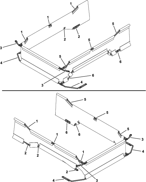
Thread 1 front, upper support rod, 1 front, lower support rod, 1 left, upper support rod, 1 right, upper support rod, 1 left, lower support rod, and 1 right, lower support rod into the skirt guard assembly (Figure 13).
-
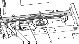
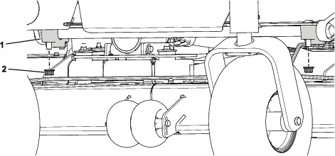
Remove the 2 button-head bolts (5/16 x 3/4 inch) and 2 flange nuts (5/16 inch) from the front of the mower deck (Figure 14).
Retain the 2 button-head bolts (5/16 x 3/4 inch) and 2 flange nuts (5/16 inch).
-
Position the assembled skirt guard underneath the frame, behind the caster wheels.
-
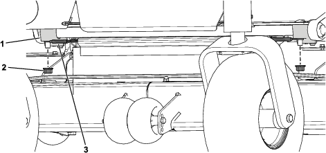
Secure the front, lower support rod using the previously removed 2 button-head bolts (5/16 x 3/4 inch) and 2 flange nuts (5/16 inch) as shown in Figure 15.
-
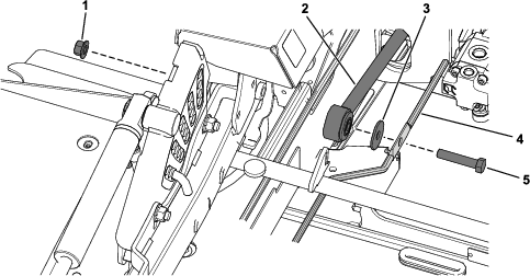
Remove the front, right flange nut (3/8 inch) from the gearbox mount and the hex-head bolt (1/2 x 2-1/2 inches), washer, and locknut (1/2 inch) from each mower deck strut (Figure 16 and Figure 17).
Retain the flange nut (3/8 inch), 2 hex-head bolts (1/2 x 2-1/2 inches), 2 washers, and 2 locknuts (1/2 inch).
-
Secure the right, lower support rod to the deck strut and gearbox mount using the previously removed flange nut (3/8 inch), hex-head bolt (1/2 x 2-1/2 inches), washer, and locknut (1/2 inch) as shown in Figure 18 and Figure 19.
-
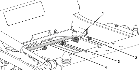
Secure the left, lower support rod to the front, lower support rod using the previously removed hex-head bolt (1/2 x 2-1/2 inches) and locknut (1/2 inch) and new 1 flange-head bolt (5/16 x 3/4 inch), 1 washer, and 1 flange nut (5/16 inch) as shown in Figure 20.
-
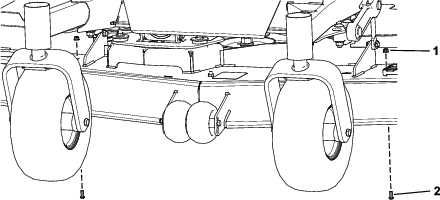
Remove the 2 locknuts (1/2 inch) from the front cross-shaft supports (Figure 21).
-
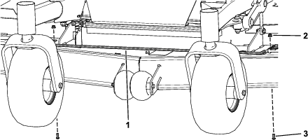
Secure the front, upper support rod to the front cross-shaft supports using the previously removed 2 locknuts (1/2 inch) to the front cross-shaft support (Figure 22).
-
Torque the 2 locknuts (1/2 inch) to 77 to 126 N∙m (57 to 93 ft-lb).
-
Secure the left, upper support rod and right, upper support rod to the brace bracket using 2 flange-head bolts (5/16 x 3/4 inch) and 2 flange nuts (5/16 inch) on each side (Figure 23).
Installing the Frame Guards
Parts needed for this procedure:
| Left frame guard | 1 |
| Right frame guard | 1 |
| Flange-head bolt (5/16 x 3/4 inch) | 4 |
| Flange nut (5/16 inch) | 4 |
Secure the left frame guard and right frame guard to the frame brackets using 2 flange-head bolts (5/16 x 3/4 inch) and 2 flange nuts (5/16 inch) on each side (Figure 24).
Installing the CE Covers
Parts needed for this procedure:
| Left CE cover | 1 |
| Right CE cover | 1 |
Installing the Floor Pan
Parts needed for this procedure:
| Captive adapter | 1 |
| Flange-head bolt (1/4 x 3/4 inch) | 2 |
| Flat washer | 2 |
| Clip | 2 |
| Push nut | 2 |
Applying the Decals
Parts needed for this procedure:
| Decal 133-5623 | 1 |
| Decal 144-6905—60-inch decks with 25 HP Yanmar diesel engine only | 1 |
| Decal 144-6906—72-inch decks with 25 HP Yanmar diesel engine only | 1 |
| Decal 144-6907—60-inch decks with 37 HP Yanmar diesel engine only | 1 |
| Decal 144-6908—72-inch decks with 37 HP Yanmar diesel engine only |
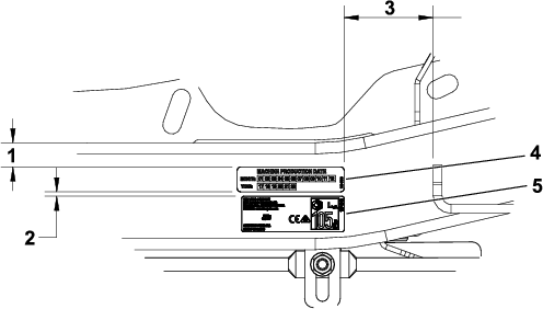
Apply decals 133-5623 and 144-6905, 144-6906, 144-6907, or 144-6908 to the left side of the machine frame near the serial decal using the dimensions shown in Figure 29.