
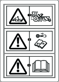
 , which means
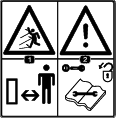
Caution, Warning, or Danger—personal safety instruction. Failure
to comply with these instructions may result in personal injury or
death.
, which means
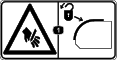
Caution, Warning, or Danger—personal safety instruction. Failure
to comply with these instructions may result in personal injury or
death.


Maintenance
Recommended Maintenance Schedule(s)
| Maintenance Service Interval | Maintenance Procedure |
|---|---|
| After the first 20 hours |
|
| Every 100 hours |
|
| Yearly |
|
Caution
If you leave the key in the switch, someone could accidently start the engine and seriously injure you or other bystanders.
Remove the key from the switch before you perform any maintenance.
Maintenance Safety
-
Before adjusting, cleaning, servicing, or leaving the machine, do the following:
-
Position the machine on a level surface.
-
Move the throttle switch to the low-idle position.
-
Disengage the PTO (if applicable).
-
Ensure that the traction is in neutral.
-
Engage the parking brake.
-
Shut off the engine of the traction unit and remove the key.
-
Wait for all moving parts to stop.
-
Allow machine components to cool before performing maintenance.
-
-
Perform only those maintenance instructions described in this manual. If major repairs are ever needed or assistance is desired, contact an authorized Bullseye distributor.
-
Ensure that the machine is in safe operating condition by keeping nuts, bolts, and screws tight.
-
If possible, do not perform maintenance while the engine is running. Keep away from moving parts.
-
Carefully release pressure from components with stored energy.
-
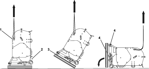
Support the machine with blocks or storage stands when working beneath it. Never rely on the hydraulic system to support the machine.
-
Never crawl under the attachment. If necessary, tilt the attachment.
-
Ensure that all guards are installed and secured after maintaining or adjusting the machine.
-
To ensure safe, optimal performance of the machine, use only genuine Bullseye replacement parts. Replacement parts made by other manufacturers could be dangerous, and such use could void the product warranty.
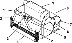
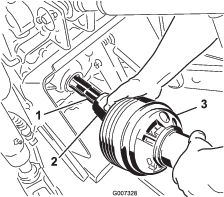
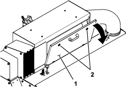
Greasing the Attachment
| Maintenance Service Interval | Maintenance Procedure |
|---|---|
| After the first 20 hours |
|
| Every 100 hours |
|
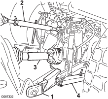
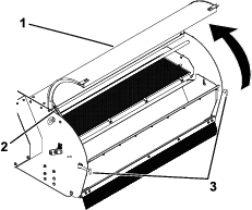
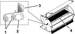
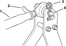
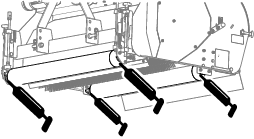
The attachment has grease fittings that you must lubricate regularly with No. 2 lithium grease. Also, lubricate the attachment immediately after every washing and after long periods without use.
Wipe up any excess grease.
-
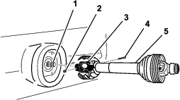
Roller bearings (4)
-
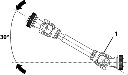
PTO driveshaft (3)
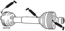
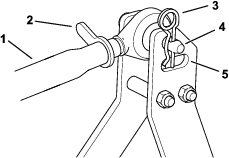
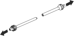
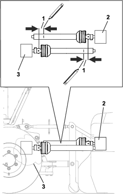
Servicing the PTO
| Maintenance Service Interval | Maintenance Procedure |
|---|---|
| Yearly |
|
-
Park the machine on a level surface, engage the parking brake, shut off the engine, and remove the key from the traction unit.
-
Secure the attachment from movement.
-
Disconnect the PTO from the traction unit and attachment.
-
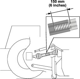
Inspect the PTO components for damage; replace any damaged or worn components.
-
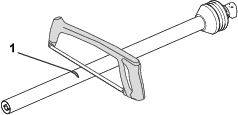
Clean all interlocking components.
-
Reassemble the components.
-
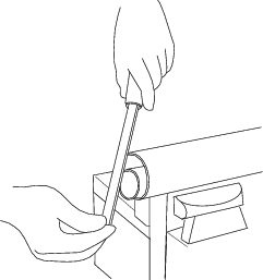
Grease the cylinders.
-
Assemble the PTO and mount it on the attachment.
Checking the Belt Tension
| Maintenance Service Interval | Maintenance Procedure |
|---|---|
| After the first 20 hours |
|
| Every 100 hours |
|
-
Park the machine on a level surface, engage the parking brake, shut off the engine, and remove the key from the traction unit.
-
Secure the attachment from movement.
-
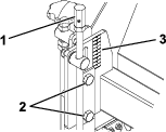
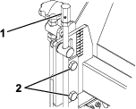
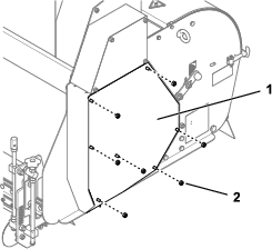
Remove the nuts and side panel.
-
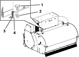
Verify that the belt deflects 2 mm (0.08 inch) when pulled with 4.5 kg (9.9 lb) of force at mid-span.
-
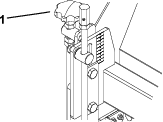
If needed, proceed to Adjusting the Belt Tension. Otherwise, install the side panel and secure it with the nuts (Figure 37).
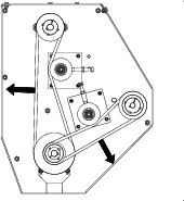
Adjusting the Belt Tension
Depending on the intensity of operation, wear on the driveline can cause the V-belts to slip. Tighten the V-belts when this occurs.
-
Park the machine on a level surface, engage the parking brake, shut off the engine, and remove the key from the traction unit.
-
Secure the attachment from movement.
-
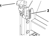
Remove the nuts and side panel.
-
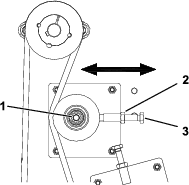
Loosen the locknut.
-
Loosen the pulley nut slightly to release the tension.
-
Adjust the bolt to increase or decrease the pressure of the pulley on the belt.
-
Verify that the belt deflects 2 mm (0.08 inch) when pulled with 4.5 kg (9.9 lb) of force at mid-span. Continue adjusting the tension as needed.
-
Tighten the pulley nut.
-
Tighten the locknut.
-
Install the side panel and secure it with the nuts.
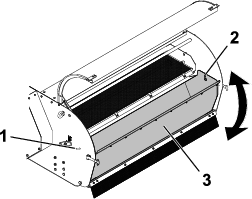
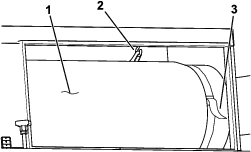
Changing the Sieve
Optional meshes are available and may be needed for processing different types of material.
-
Park the machine on a level surface, engage the parking brake, shut off the engine, and remove the key from the traction unit.
-
Secure the attachment from movement.
-
Open the inspection hatch.
-
Rotate the clips to release the sieve.
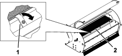
-
Remove the sieve and replace it with another sieve.
-
Turn the clips to secure the sieve.
-
Carefully close the inspection hatch and secure it using the latches.