Note: Determine the left and right sides of the machine from the normal operating position.
Installation
Preparing the Machine
-
Park the machine on a level surface.
-
Engage the parking brake.
-
Lower the cutting unit.
-
Shut off the engine and remove the key.
Drilling Holes for the Idler Assembly
Parts needed for this procedure:
| Template |
-
Open the hood.
-
Remove the tension on the belt and move the belt away from the installation area.
-
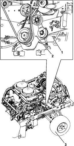
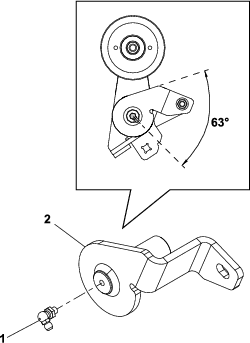
Remove the roll pin, bolt, and the existing idler pulley shown in Figure 1.
-
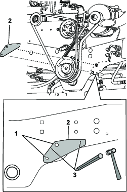
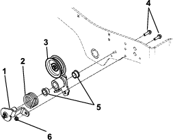
Align the template to the frame using the holes labeled 1 in Figure Figure 2.
-
Punch the location of the holes labeled 3 in Figure 2.
-
Remove the template.
-
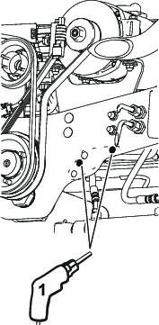
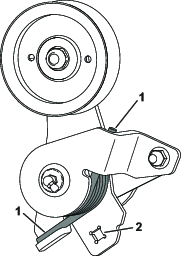
Drill 2 holes (13/32 inch) at the punched locations (Figure 3).
Installing the Idler Pulley
Parts needed for this procedure:
| Idler pulley | 1 |
| Idler arm | 1 |
| Idler support | 1 |
| Spring | 1 |
| Flange locknut (3/8 inch) | 1 |
| Bolt (1/2 x 1-3/4 inches) | 1 |
| Locknut (1/2 inch) | 1 |
| Spacer | 1 |
| Grease fitting | 1 |
| Bushing | 2 |
| Hex flange bolt (3/8 x 1-1/4 inches) | 2 |
-
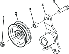
Install the idler pulley to the idler arm with a bolt (1/2 x 1-3/4 inches), spacer, and 1 locknut (1/2 inch); refer to Figure 4.
-
Install the grease fitting into the idler support as shown in Figure 5.
-
Install the idler support and idler arm to the frame of the machine with 2 bolts (3/8 x 1-1/4 inches), 2 bushings, a spring, and a nylon locknut (3/8 inch); refer to Figure 6.
-
Install the install the spring ends as shown in Figure 7.
-
Using a 3/8 inch ratchet in the square in the idler arm, rotate the idler arm and install the belt around the idler pulley (Figure 7).
-
Close the hood and secure it with the 2 hood latches.