Installation
Preparing the Machine
-
Park the machine on a level surface.
-
Disengage the blade-control switch (PTO), move the motion-control levers to the NEUTRAL-LOCK position, and engage the parking brake.
-
Shut off the engine, remove the key, and wait for all moving parts to stop before leaving the operating position.
-
Lower the mower deck to the lowest cutting height.
Removing the MyRide Guard
Removing the Lift Lever
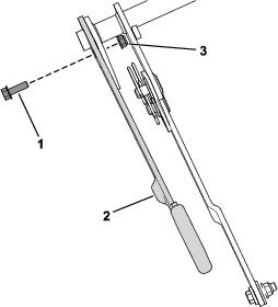
Remove the hex-head bolt (5/16 x 1 inch) and flange nut (5/16 inch) securing the lift lever (Figure 2).
Retain the lift lever for later installation. You can discard the hex-head bolt (5/16 x 1 inch) and flange nut (5/16 inch).
Installing the Foot Pedal
Parts needed for this procedure:
| Lift pedal | 1 |
| Foot peg | 1 |
| Foot-lift plate | 1 |
| Carriage bolt (5/16 x 1-1/4 inches) | 2 |
| Locknut (5/16 inch) | 2 |
| Thrust washer | 2 |
| Spacer (3/8 inch) | 1 |
| Spacer (5/16 inch) | 2 |
| Link | 1 |
| Carriage bolt (3/8 x 1 inch) | 1 |
| Locknut (5/16 inch) | 2 |
| Shoulder bolt (3/8 x 7/8 inch) | 2 |
| Locknut (3/8 inch) | 3 |
| Hex-head bolt (3/8 x 1 inch) | 1 |
| Washer | 1 |
| Nylon washer | 1 |
| Anti-seize packet | 1 |
-
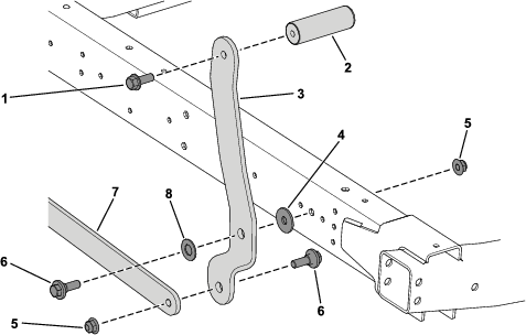
Secure the foot peg to the lift pedal using 1 hex-head bolt (3/8 x 1 inch) as shown in Figure 3.
-
Secure the lift pedal to the link using 1 shoulder bolt (3/8 x 7/8 inch) and 1 locknut (3/8 inch) as shown in Figure 3.
-
Secure the lift pedal to the side of the frame using 1 shoulder bolt (3/8 x 7/8 inch), 1 nylon washer, 1 washer, and 1 locknut (3/8 inch) as shown in Figure 3.
-
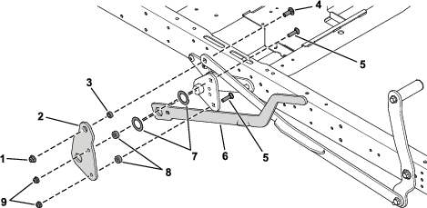
Apply anti-seize to both sides of the 2 thrust washers.
-
Install the thrust washers on each side of the lift lever (Figure 4).
Note: Install all the carriage bolts with the bolt heads on the inside of the machine.
-
Secure the foot-lift plate to the link using 1 carriage bolt (3/8 x 1 inch), 2 carriage bolts (5/16 x 1-1/4 inches), 1 spacer (3/8 inch), 2 spacers (5/16 inch), 1 locknut (3/8 inch), and 2 locknuts (5/16 inch) as shown in Figure 4.
Completing the Setup
-
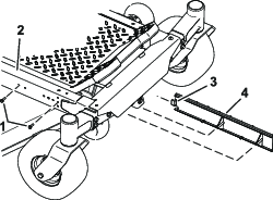
For machines with the MyRide Suspension System, slide the guard tab into the frame (Figure 1).
-
For machines with the MyRide Suspension System, install the bolts into the frame and guard (Figure 1).
-
Use the height-of-cut lever and foot pedal to raise and lower the mower deck, check to see if there is any binding. If so, check the installation.
-
Adjust as necessary.