Installation
Note: Determine the left and right sides of the machine from the normal operating position.
Preparing the Machine
-
Park the machine on a level surface.
-
Disengage the blade-control switch.
-
Move the motion-control levers outward to the NEUTRAL-LOCK position.
-
Engage the parking brake.
-
Lower the mower deck to the lowest height of cut.
-
Shut off the engine and remove the key.
-
Disconnect the negative-battery cable.
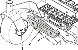
Removing the Existing Front Bumper
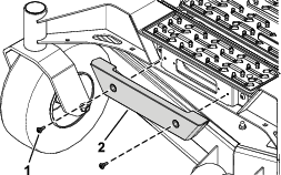
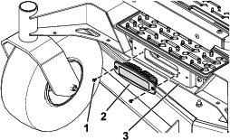
Installing the Light and Front Bumper
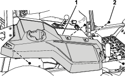
Removing the Right Side Pod
Installing the Headlight Rocker Switch
Parts needed for this procedure:
| Headlight rocker switch | 1 |
-
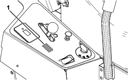
Cut out the opening in control panel decal for the headlight rocker switch (Figure 5).
-
Install the headlight rocker switch into the control panel (Figure 6).
Orient the terminals on the rocker switch toward the rear of the machine.
Orient the ON position of the switch toward the front of the machine and the OFF position toward the rear of the machine.
Routing and Connecting the Wire Harness
Parts needed for this procedure:
| Wire harness | 1 |
-
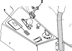
Remove the cap from the auxiliary connector on the machine wire harness (Figure 7).
-
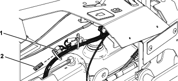
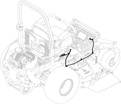
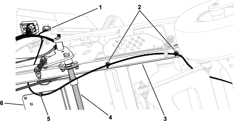
Route light kit wire harness along the right side of the machine frame and secure it using the 2 magnetic tie-mount wraps and 2 push-mount fasteners (Figure 8 and Figure 9).
Ensure that you route the light kit wire harness underneath the deck-lift cross shafts as shown in Figure 9.
-
Connect the light kit wire harness to the headlight (Figure 8).
-
Connect the light kit wire harness to the headlight rocker switch (Figure 9).
-
Connect the light kit wire harness to the auxiliary connector on the machine wire harness (Figure 7).
Installing the Right Side Pod
Secure the right side pod using the previously removed 4 shoulder screws (Figure 4).
Connecting the Battery
Connect the negative-battery cable.