Introduction

Read this information carefully to learn how to operate and maintain your product properly and to avoid injury and product damage. You are responsible for operating the product properly and safely.

Visit www.Toro.com for more information, including safety tips, training materials, accessory information, help finding a dealer, or to register your product.

Whenever you need service, genuine Toro parts, or additional information, contact an Authorized Service Dealer or Toro Customer Service and have the model and serial numbers of your product ready. Figure 1 identifies the location of the model and serial numbers on the product. Write the numbers in the space provided.

g003797

This manual identifies potential hazards and has safety messages identified by the safety-alert symbol (Figure 2), which signals a hazard that may cause serious injury or death if you do not follow the recommended precautions.

g000502

This manual uses 2 words to highlight information. Important calls attention to special mechanical information and Note emphasizes general information worthy of special attention.

Safety

Safety and Instructional Decals

Graphic

Safety decals and instructions are easily visible to the operator and are located near any area of potential danger. Replace any decal that is damaged or missing.

decal106-5517

Setup

Mounting the Finish Grader

Parts needed for this procedure:

Finish grader1

Note: Determine the left and right sides of the machine from the normal operating position.

  1. Remove any attachment from the rear of the machine.

  2. Back the traction unit into position in front of the attachment adapter. Lower the traction unit adapter.

    Note: Ensure that the locking lever is pivoted to the left (unlocked position) as viewed from the rear of the machine (Figure 3).

    g003650
  3. Raise the traction unit adapter into the attachment adapter.

  4. Pivot the locking lever to the right (locked position) as viewed from the rear of the machine so that it is standing straight up to lock the adapters together.

Adjusting the Link Assembly

  1. With the attachment mounted and secured on the traction unit, raise the attachment.

  2. Measure the gap between the top washer and the spacer in the link assembly on the attachment adapter as shown in Figure 4.

    Important: The gap between the washer and the shoulder should be 0.060 to 0.080 inch (1.5 to 2.0 mm).

    g347343

Finishing the Setup

Before operating the finish grader, review the following materials and save them in an appropriate place:

  • Parts Catalog

  • Installation Instructions

Operation

Operating the Finish Grader

  • Raise or lower the finish grader to control the grading or scarifying depth.

  • When grading, rotate the scarifier to the upper position and secure each end with a clevis pin and hairpin (Figure 5).

    g348148
  • When scarifying, rotate the scarifier to the lower position and secure each end with a clevis pin and hairpin (Figure 5).

  • The scarifier aggressiveness can be changed by adjusted the length of the springs (Figure 8). Lengthening the springs will make the scarifier less aggressive. Shortening the springs will make the scarifier more aggressive

  • For final grading/leveling, an Adjustable Orifice Kit (Part No. 112-1433) can be obtained to regulate the raise/lower speeds.

Inspecting and Cleaning the Finish Grader

When the grading operation is completed, clean the machine thoroughly. Since this machine is used primarily in extremely abrasive conditions, the material should be flushed off after each use. If the machine is cleaned frequently, it can be cleaned with a stream of water from a hose with the nozzle removed.

Important: Do not use pressurized water to clean the machine; a high pressure stream could drive sand or other material into wear areas where it could act as a grinding compound.

Note: If the attachment adapter becomes stuck to the traction unit adapter, insert a prybar/screwdriver into the pry slot to disengage the parts.

g003783

Maintenance

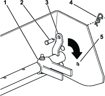
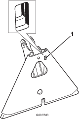
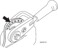
Greasing the Attachment Adapter

If the locking lever on the attachment adapter does not pivot freely and easily, apply a light coat of grease to the area shown in Figure 7.

g003731

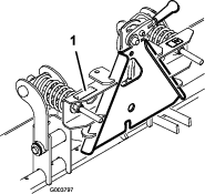
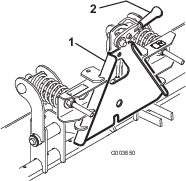
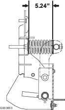
Adjusting the Actuating Rod Springs

The springs and actuating rods are adjusted at the factory. However, if new parts are installed or the springs are removed for any reason, the spring length should be adjusted to 5.24 inches (133 mm) as shown in Figure 8.

g003653

Leveling the Finish Grader Blade

To level the blade in relation to the traction unit, place the unit on a level surface (such as a concrete driveway), and slightly vary the rear tire pressure as required.

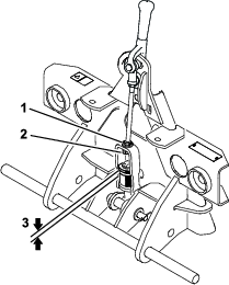
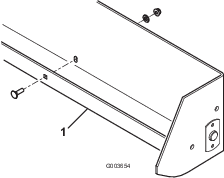
Reversing the Scraper Blade

The scraper blade (Figure 9) can be reversed for a second wear surface after the original edge has worn beyond the lower edge of the finish grader box that it is attached to.

g003654

Optional Equipment

Drag kit Part No. 140-0274
Weight Kit (Required when using 140-0274)Part No. 100-6442
Carbide Tine Pack (15 tines included)Part No. 119-2152
Weeder Tine (15 tines required per machine)Part No. 110-0260-0P
Weeder Blade (5 blades required per machine)Part No. 132-4427-0P