Setup
Note: Determine the left and right sides of the machine from the normal operating position.
Removing the Machine from the Crate
Parts needed for this procedure:
| Mower deck | 1 |
| Machine | 1 |
| Hopper door | 1 |
-
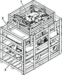
Remove the 4 planks that attach the mower-deck crate to the traction-unit crate.
-
Remove the mower deck crate (Figure 1).
-
Remove the hopper door from the crate (Figure 1).
-
Remove the front panel, plastic bags, and other packaging material.
-
Remove all the packaged machine components attached to the pallet.
-
Remove the wood over the seat that is used to support the hopper door.
-
Remove the rear bumper and the light assembly.
-
Remove the wooden blocks from the wheels and the steel hooks.
-
Charge and connect the battery; refer to the Operator’s Manual.
-
Remove the machine from the crate (Figure 1).
Installing the Hopper Door
Parts needed for this procedure:
| Flat washer | 6 |
| Bolt | 2 |
| Locknut | 2 |
-
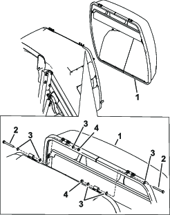
Remove the hardware from the brackets on the hopper.
-
Install the hopper door to the hopper with the previously removed hardware; refer to Figure 2.
Installing the Latch
Parts needed for this procedure:
| Hook | 1 |
| Spacer | 1 |
| Long bolt | 2 |
| Short bolt | 1 |
| Flat washer | 3 |
| Rod connector | 1 |
| Spring | 1 |
| Bushing | 2 |
| Flange nut | 3 |
| Locknut | 2 |
-
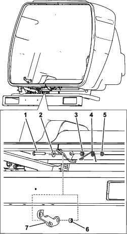
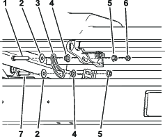
Install the hook and spacer to the hopper with a long bolt, flat washer, flange nut, spring, and locknut (Figure 3).
-
Install the rod connector to the hook with a long bolt, flat washer, bushing, flange nut, and locknut (Figure 4).
Note: Ensure that the locknut is not fully installed onto the bolt. The space between the flange nut and locknut is used for the spring (Figure 6).
-
Install the rod connector to the hook with a short bolt, flat washer, bushing, and locknut. (Figure 4).
-
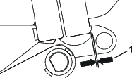
Check the gap between the hook and the closed hopper door. Ensure that the gap is 2 mm (1/16 inch) and adjust if necessary (Figure 5).
-
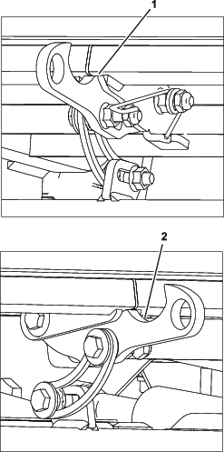
Install the spring ends as shown in Figure 6.
Installing the Rear Bumper
Parts needed for this procedure:
| Rear bumper | 1 |
| Bolt | 4 |
| Flat washer | 8 |
| Locknut | 4 |
| Cable ties | 4 |
-
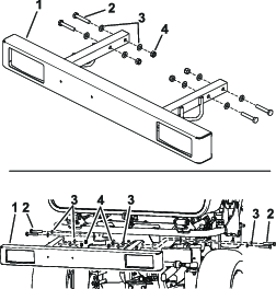
Remove the hardware from the rear bumper (Figure 7).
-
Install the rear bumper under the hopper with the previously removed hardware (Figure 7).
-
Connect the wire harness to the machine harness.
-
Verify that the left and right turn lights are hooked up correctly by using the turn signal. If needed, change the connections.
-
Use the cable ties to fasten the wire harness to the rear bumper.
Installing the Front Lights
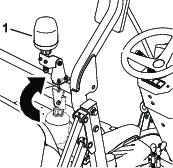
Positioning the Beacon Light
-
Raise the rollbar; refer to the Operator’s Manual.
-
Rotate the beacon light to the upright position and secure the fasteners.
Installing the Decals
Parts needed for this procedure:
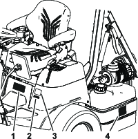
| Warning decal | 1 |
| Spark arrestor/Prop 65 decal | 1 |
| Diesel fuel decal | 1 |
Note: Ensure the decals are installed at the time of sale or shown to the public for the countries listed in the table on page 8.
Install the warning decal, spark arrestor decal, and the diesel fuel decal (Figure 10).
Completing the Setup
Complete the setup instructions that are in the Operator’s Manual.
| ISO | Language | ISO | Language | ISO | Language | ||
| AI | Anguilla | GU | Guam | PR | Puerto Rico | ||
| AG | Antigua and Barbuda | GT | Guatemala | LC | Saint Lucia, Saint Kitts and Nevis | ||
| AR | Argentina | GY | Guyana | VC | Saint Vincent, Grenadines | ||
| BS | Bahamas | HT | Haiti | AS | Samoa, American | ||
| BB | Barbados | IN | India | SG | Singapore | ||
| Bz | Belize | IL | Israel | LK | Sri Lanka | ||
| BM | Bermuda | JM | Jamaica | SR | Suriname | ||
| BO | Bolivia | LB | Lebanon | TW | Taiwan | ||
| VG | British Virgin Islands | MY | Malaysia | TH | Thailand | ||
| BN | Brunei | MV | Maldives | TT | Trinidad and Tobago | ||
| BU | Burma (Myanmar) | MU | Mauritius | TN | Tunisia | ||
| CA | Canada | MX | Mexico | TC | Turks and Caicos Islands | ||
| KY | Cayman Islands | UM | Minor Outlying Islands | AE | United Arab Emirates | ||
| CO | Colombia | MS | Montserrat | US | United States | ||
| CR | Costa Rica | MP | Northern Mariana Islands | VI | U.S. Virgin Islands | ||
| DM | Dominica | OM | Oman | UY | Uruguay | ||
| EC | Ecuador | Pa | Panama | VE | Venezuela | ||
| EG | Egypt | PY | Paraguay | VN | Vietnam | ||
| FJ | Fiji | PE | Peru | ||||
| GD | Grenada | PH | Philippines | ||||
