Introduction

The dethatching unit is mounted to a traction unit and is intended to be used by professional, hired operators in commercial applications. It is designed primarily for dethatching grass on well-maintained lawns in parks, golf courses, sports fields, and on commercial grounds. Using this product for purposes other than its intended use could prove dangerous to you and bystanders.

Read this information carefully to learn how to operate and maintain your product properly and to avoid injury and product damage. You are responsible for operating the product properly and safely.

Visit www.Toro.com for product safety and operation training materials, accessory information, help finding a dealer, or to register your product.

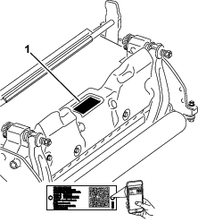
Whenever you need service, genuine Toro parts, or additional information, contact an Authorized Service Dealer or Toro Customer 
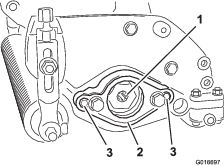
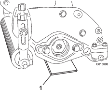
Service and have the model and serial numbers of your product ready. Figure 1 identifies the location of the model and serial numbers on the product. Write the numbers in the space provided.

g272197

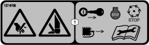
This manual identifies potential hazards and has safety messages identified by the safety-alert symbol (Figure 2), which signals a hazard that may cause serious injury or death if you do not follow the recommended precautions.

g000502

This manual uses 2 words to highlight information. Important calls attention to special mechanical information and Note emphasizes general information worthy of special attention.

This product complies with all relevant European directives. For details, please see the Declaration of Incorporation (DOI) at the back of this publication.

Safety

This machine has been designed in accordance with EN ISO 5395 and ANSI B71.4:2017.

General Safety

This product is capable of amputating hands and feet. Always follow all safety instructions to avoid serious personal injury.

  • Read and understand the contents of this Operator’s Manual before starting the machine.

  • Use your full attention while operating the machine. Do not engage in any activity that causes distractions; otherwise, injury or property damage may occur.

  • Do not put your hands or feet near moving components of the machine.

  • Do not operate the machine without all guards and other safety protective devices in place and functioning properly on the machine.

  • Keep clear of any discharge opening.

  • Keep bystanders and children out of the operating area. Never allow children to operate the machine.

  • Before you leave the operator’s position, do the following:

    • Park the machine on a level surface.

    • Lower the cutting unit(s).

    • Disengage the drives.

    • Engage the parking brake (if equipped).

    • Shut off the engine and remove the key (if equipped).

    • Wait for all movement to stop.

Improperly using or maintaining this machine can result in injury. To reduce the potential for injury, comply with these safety instructions and always pay attention to the safety-alert symbol Graphic, which means Caution, Warning, or Danger—personal safety instruction. Failure to comply with these instructions may result in personal injury or death.

Cutting Unit Safety

  • The cutting unit is only a complete machine when installed on a traction unit. Read the traction unit Operator’s Manual carefully for complete instructions on the safe use of the machine.

  • Stop the machine, remove the key (if equipped), and wait for all movement to stop before inspecting the attachment after striking an object or if there is an abnormal vibration in the machine. Make all necessary repairs before resuming operation.

  • Keep all parts in good working condition and all hardware tightened. Replace all worn or damaged decals.

  • Use only accessories, attachments, and replacement parts approved by Toro.

Blade Safety

A worn or damaged blade can break, and a piece of the blade could be thrown toward you or bystanders, resulting in serious personal injury or death.

  • Inspect the blade periodically for wear or damage.

  • Use care when checking the blades. Wrap the blades or wear gloves, and use caution when servicing the blades. Only replace or sharpen the blades; never straighten or weld them.

  • On multi-bladed machines, take care as rotating 1 blade can cause other blades to rotate.

Safety and Instructional Decals

Graphic

Safety decals and instructions are easily visible to the operator and are located near any area of potential danger. Replace any decal that is damaged or missing.

decal137-9706

Setup

Installing the Front Roller

The dethatching unit is shipped without a front roller. Install the roller using the loose parts supplied with the dethatching unit and Installation Instructions included with the roller.

Repositioning the Counterweights

The dethatching units are shipped with the counterweight mounted to the right end and the motor mount to the left end of the dethatching unit. To move the counterweight to the other side of the dethatching unit, do the following steps:

  1. Remove the 2 capscrews that secure the counterweight to the right end of the dethatching unit.

  2. Remove the counterweight (Figure 3).

    g016405
  3. Remove the 2 Allen-head screws that secure the motor mount to the left end of the dethatching unit.

  4. Remove the motor mount (Figure 4).

  5. Apply grease to the inside diameter of the drive spline (Figure 4).

    g016697
  6. On the right end of the dethatching unit, apply a light coating of oil to the O-ring and install the motor mount with the 2 Allen-head screws previously removed.

    Note: Torque the screws to 16 to 20 N-m (12 to 15 ft-lb).

  7. On the left end of the dethatching unit, apply a light coating of oil to the O-ring and install the counterweight with the screws previously removed.

    Note: Torque the screws to 16 to 20 N-m (12 to 15 ft-lb).

Installing the Hoop Link, Offset Link, or Chain Link

For dethatching units that will be mounted on a traction unit with a serial number prior to 240000001, the proper lift link must be obtained and installed.

The 2 capscrews used to mount the hoop, offset, or chain link are installed on the dethatching unit. Remove these screws and use them to install your required link.

  • A hoop link (Part No. 105-5740) as shown in Figure 5 is required for the Greensmaster 3000, 3000-D, 3050, 3100, 3150, and 3150-Q traction units (it is supplied with the above Greensmaster traction units).

    1. Install the hoop link to the top of the dethatching unit with 2 capscrews.

    2. Torque the capscrews to 34 to 40 N∙m (25 to 30 ft-lb).

    g011931
  • An offset link (Part No. 110-2397) is required for the Greensmaster 3250-D traction units (it is supplied with the Greensmaster 3250-D traction unit).

    1. Position the lift hook offset toward the front of the dethatching unit.

    2. Install the offset link (Figure 6) to the top of the dethatching unit with 2 capscrews.

    3. Torque the capscrews to 34 to 40 N∙m (25 to 30 ft-lb).

    g008414
  • A chain link (Part No. 106-2601) and a mounting bracket (Part No. 105-5738) may also be used on the Greensmaster 3250-D traction unit.

    1. Install the chain link to the top of the dethatching unit with the mounting bracket and 2 capscrews.

    2. Torque the capscrews to 34 to 40 N∙m (25 to 30 ft-lb) (Figure 7).

    Note: When mounting the dethatching unit to the traction unit, hook the wider end of the chain link to the lift arm.

    g011932

Adjusting the Reel Blades for Positive Setting (Above Ground)

  1. Place the dethatching unit on a level surface.

  2. Place a gauge bar, which has the desired height of blade above ground, under each end of the dethatching unit (Figure 8).

    g016698
  3. With the rear roller contacting the level surface, loosen both height-of-cut nuts.

  4. Rotate the height-of-cut until both ends of the front roller contact the level surface.

  5. Verify contact by using a piece of paper to check each roller end.

  6. Tighten both height-of-cut knob locknuts.

Adjusting the Reel Blades For Negative Setting (Below Ground)

Note: Maximum recommended negative setting is 5 mm (3/16 inch) deep blade penetration.

  1. Place the dethatching unit on a level surface.

  2. Place 4 gauge bars, set to the desired depth of blade penetration below ground, under the front roller and rear roller of the dethatching unit (Figure 9).

    g016696
  3. With the rear roller contacting the level surface, loosen both height-of-cut nuts.

  4. Rotate the height-of-cut until both ends of the front roller contact the level surface.

  5. Verify contact by using a piece of paper to check each roller end.

  6. Tighten both height-of-cut knob locknuts.

Installing the Dethatching Unit

Important: If you set the dethatching reel at a negative setting, take care to prevent damaging the reel blades, due to contact with concrete floors or paved surfaces.

Note: The dethatching unit comes configured for left-hand drive from the factory. It may need to be configured for a right-hand drive. Refer to Repositioning the Counterweights.

Product Overview

Traction-Unit CompatibilityThe dethatching unit mounts on the Greensmaster 3000, 3000-D, 3050, 3100, 3150, 3250-D and 3150-Q traction units.
Height of CutDethatching depth is adjusted on the front roller by two vertical screws and held by two locking capscrews
Height-of-Cut RangeBench HOC range is 4.78 mm (0.188 inch) below ground level to 6.35 mm (0.250 inch) above ground level.
Reel BearingsTwo sealed stainless steel deep groove ball bearings, 30 mm inside diameter slip fit onto reel shaft retained by internally splined threaded drive insert. Additional inboard seal / slinger along with sealed external bearing housing for added protection. Reel position maintained by a wave washer with no adjusting nut.
RollersThe rear roller is a 5.1 cm (2 inch) diameter steel full roller.
Grass ShieldNon-adjustable shield with adjustable cutoff bar to improve grass discharge from reel in wet conditions.
CounterweightA cast iron weight mounted opposite to the drive motor balances the dethatching unit.
Net Weight31 kg (68 lb)

Attachments/Accessories

A selection of Toro approved attachments and accessories is available for use with the machine to enhance and expand its capabilities. Contact your Authorized Service Dealer or authorized Toro distributor or go to www.Toro.com for a list of all approved attachments and accessories.

To ensure optimum performance and continued safety certification of the machine, use only genuine Toro replacement parts and accessories. Replacement parts and accessories made by other manufacturers could be dangerous, and such use could void the product warranty.

Operation

Training Period

Before operating the dethatching unit on a green, evaluate the performance of the dethatching unit at the desired setting. Operate in a clear, unused area to determine if the desired results will be achieved. Adjust the dethatching unit when changing settings as desired.

Note: When the dethatching units are mounted on Greensmaster 3200, 3200-D or 3250-D traction units and are operated under heavy loads, you may need to adjust the carrier frame and unit circuit relief valve.

Operating Tips

  • Operate the traction unit at full throttle, varying the ground speed to meet dethatching loads.

  • The maximum recommended negative setting on the dethatching blades is 5 mm (3/16 inch) deep penetration.

  • The power requirements to operate the dethatching unit will vary with turf and soil conditions.

  • The travel speed may need to be reduced in some conditions.

Maintenance

Note: Determine the left and right sides of the machine from the normal operating position.

Disassembling the Reel

Disassemble the reel whenever you need to change a blade or replace the reel bearings.

Important: Ensure that the 2 shaft retainers and spacer are in place before installing the bearing on the reel (Figure 10). Torque the insert nuts to 136 N∙m (100 ft-lb).

g016597

If you install the optional spring steel dethatcher blades (Part Number 121-6675), replace the end hex spacer (Part Number 120-3232—shown in Figure 11) with a main spacer (Part Number 120-3167).

Contact your authorized Toro distributor for parts information.

Note: The end hex spacer is located between a pair of hex spacers and a hex nut as shown in Figure 11.

g346400