
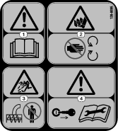
 , which means Caution, Warning,
or Danger—personal safety instruction. Failure to comply with
these instructions may result in personal injury or death.
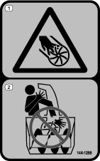
, which means Caution, Warning,
or Danger—personal safety instruction. Failure to comply with
these instructions may result in personal injury or death.


Maintenance
Determine the left and right sides of the machine from the normal operating position.
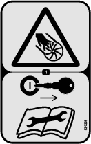
Caution
If you leave the key in the switch, someone could accidently start the engine and seriously injure you or other bystanders.
Remove the key from the switch before you perform any maintenance.
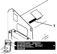
Recommended Maintenance Schedule(s)
| Maintenance Service Interval | Maintenance Procedure |
|---|---|
| Before each use or daily |
|
| Every 100 hours |
|
| Before storage |
|
| Yearly or before storage |
|
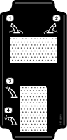
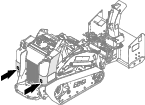
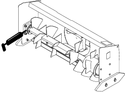
Greasing the Snow Thrower
| Maintenance Service Interval | Maintenance Procedure |
|---|---|
| Before each use or daily |
|
| Before storage |
|
Grease Type: General-purpose grease
-
Park the machine on a level surface and engage the parking brake (if equipped).
-
Shut off the engine, remove the key, and wait for all moving parts to stop before leaving the operating position.
-
Grease the bearing.
-
Wipe up any excess grease.
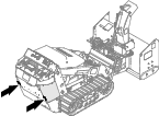
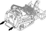
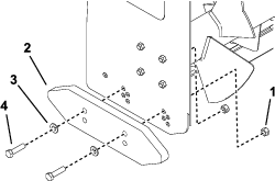
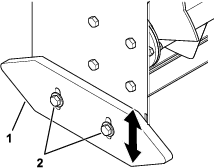
Checking and Replacing the Skids
| Maintenance Service Interval | Maintenance Procedure |
|---|---|
| Every 100 hours |
|
| Yearly or before storage |
|
Check the skids for wear. Rotate the skids or replace them when worn.
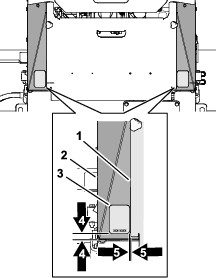
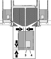
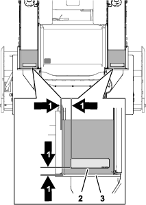
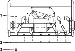
Replacing the Scraper Blade
| Maintenance Service Interval | Maintenance Procedure |
|---|---|
| Every 100 hours |
|
| Yearly or before storage |
|
The scraper blade contacts the ground to prevent damage to the snow thrower housing. Periodically inspect the scraper blade for wear. Rotate or replace it when it becomes worn, before the working surface contacts the housing.
-
Park the machine on a level surface and engage the parking brake (if equipped).
-
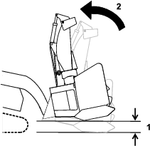
Raise the snow thrower 30 cm (12 inches) off the ground.
-
Shut off the engine and remove the key.
-
Remove the nuts, carriage bolts, and scraper blade.
Note: The snow thrower for the TXL 2000 uses 10 carriage bolts and 10 nuts.
-
Replace or rotate the scraper blade and secure it with the previously removed fasteners.
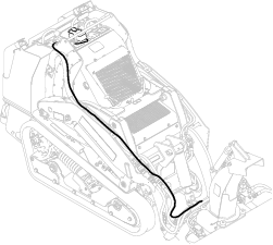
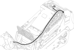
Checking the Hydraulic Lines
| Maintenance Service Interval | Maintenance Procedure |
|---|---|
| Before each use or daily |
|
Warning
Hydraulic fluid escaping under pressure can penetrate skin and cause injury. Fluid injected into the skin must be surgically removed within a few hours by a doctor familiar with this form of injury; otherwise, gangrene may result.
-
Keep your body and hands away from pinhole leaks or nozzles that eject high-pressure hydraulic fluid.
-
Use cardboard or paper to find hydraulic leaks; never use your hands.