Safety
Safety and Instructional Decals
 |
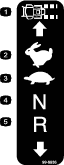
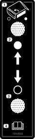
Safety decals and instructions are easily visible to the operator and are located near any area of potential danger. Replace any decal that is damaged or missing. |
Installation
Note: Determine the left and right sides of the machine from the normal operating position.
Preparing the Machine
-
Park the machine on a level surface.
-
Disengage the blade-control switch.
-
Move the motion-control levers outward to the NEUTRAL-LOCK position.
-
Engage the parking brake.
-
Shut off the engine and remove the key.
Removing the Existing Side Discharge Chute
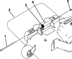
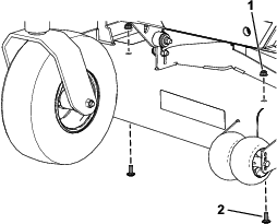
Remove the bolt, spring, spacer, and locknut securing the discharge chute and remove the discharge chute (Figure 1).
Preparing the Mower Deck
Parts needed for this procedure:
| Discharge baffle | 1 |
| Bagger baffle | 1 |
| Carriage bolt (3/8 x 7/8 inch) | 4 |
| Locknut (3/8 inch) | 4 |
| Carriage bolt (5/16 x 7/8 inch) | 1 |
| Locknut (5/16 inch) | 1 |
-
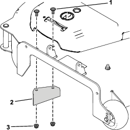
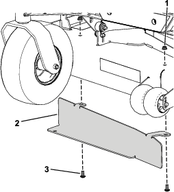
Remove the existing discharge baffle, 2 carriage bolts, and 2 locknuts (Figure 2).
Discard the fasteners.
-
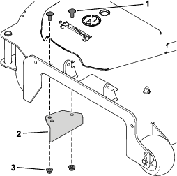
Remove the 2 carriage bolts and 2 locknuts at the front of the mower deck (Figure 3).
Discard the fasteners.
-
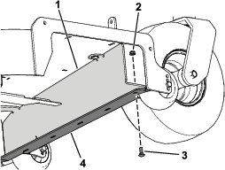
Install the bagger baffle to the mower deck and deck bumper using 2 carriage bolts (3/8 x 7/8 inch), 2 locknuts (3/8 inch), 1 carriage bolt (5/16 x 7/8 inch), and 1 locknut (5/16 inch) as shown in Figure 4 and Figure 5.
-
Install the new discharge baffle using 2 carriage bolts (3/8 x 7/8 inch) and 2 locknuts (3/8 inch) as shown in Figure 6.
Installing the Side Discharge Chute with the Gate
Parts needed for this procedure:
| Side discharge chute with gate | 1 |
| Hex-head bolt (5/16 x 7-1/2 inches) | 1 |
| Locknut (5/16 inch) | 1 |
| Spacer | 1 |
| Spring | 1 |
Warning
An uncovered discharge opening could allow the machine to throw objects toward you or bystanders, resulting in serious injury. Also, contact with the blade could occur.
Never operate the machine unless you install a mulch plate, discharge deflector, or grass collection system.
-
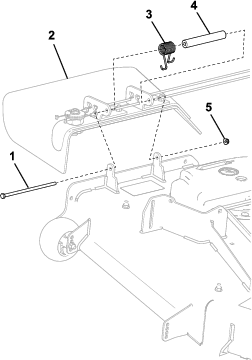
Place the new spacer and spring onto the discharge chute (Figure 7).
Place 1 end of the spring behind the deck edge.
Note: Ensure that the end of the spring is installed behind the deck edge before installing the hex-head bolt (5/16 x 7-1/2 inches).
-
Install hex-head bolt (5/16 x 7-1/2 inches) and locknut (5/16 inch) as shown in Figure 7.
Place the end of the spring around the discharge chute.
-
Tighten the locknut (5/16 inch) until the end of the hex-head bolt (5/16 x 7-1/2 inches) is flush with the end of the locknut (5/16 inch).
Do not over tighten the locknut.
Important: The discharge chute must be able to lower down into position. Lift the chute up to test that it lowers into the fully-down position.
Installing the Control Box
Parts needed for this procedure:
| Control box assembly | 1 |
| Carriage bolt (3/8 x 7/8 inch) | 2 |
| Locknut (3/8 inch) | 2 |
| Cable tie | 3 |
| Adhesive cable tie | 1 |
-
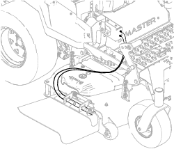
Route the cables between the control box and discharge chute as shown in Figure 8 to avoid damaging the cables through the entire height-of-cut range.
Important: Ensure that you route the cables away from the front of the deck-lift pedal as shown in Figure 8 so that you do not damage the cables.
-
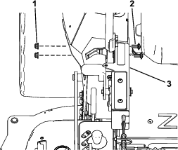
Remove the self-threading screw from the right motion-control cover (Figure 9).
Retain the self-threading screw.
-
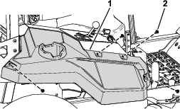
Remove the 4 shoulder screws securing the right side pod (Figure 10).
Retain the 4 shoulder screws and right side pod for later installation.
-
Remove the right side pod (Figure 10).
-
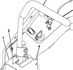
Secure the control box to the right motion-control cover using 2 carriage bolts (3/8 x 7/8 inch) and 2 locknuts (3/8 inch) as shown in Figure 11.
-
Install the previously removed self-threading screw to the right motion-control cover (Figure 9).
-
Secure the right side pod using the previously removed 4 shoulder screws (Figure 10).
-
Install the adhesive back plastic mount on a smooth, clean surface.
Thread the cable tie through the plastic mount and secure the cables with the cable tie.
-
Slowly move the mower deck through the height-of-cut range to ensure that the cables do not stretch or kink when you are operating the machine.