Installation
The Sound Reducing Kit can be installed on the following:
-
Traction units (Models 31903 and 31909)
-
Winter enclosure (Model 31990)
Preparing the Machine
-
Park the machine on a level surface.
-
Engage the parking brake.
-
Lower the attachment.
-
Shut off the engine and remove the key.
-
Disconnect the battery; refer to the electrical system maintenance section in your Operator’s Manual.
Installing the Floor Components
Parts needed for this procedure:
| Steering plug | 1 |
| Upper steering plug | 1 |
| Lower steering plug | 1 |
| Steering pad | 1 |
| Mounting-tab plug | 3 |
| Corner floor pad | 1 |
| Center floor pad | 1 |
| Brake plug—7.6 cm (3 inches) width | 1 |
| Brake plug—3.1 cm (1.22 inch) width | 1 |
| ROPS plug | 4 |
| Seat-base pad (thin) | 1 |
| Seat-base pad (thick) | 1 |
| Seat pad | 1 |
| Rear-window pad | 1 |
| Lower-firewall pad | 1 |
| Upper-firewall pad | 1 |
| Firewall tile pad | 1 |
| Upper brake foam | 1 |
| Lower brake foam | 1 |
| Right corner pad | 1 |
| Left corner pad | 1 |
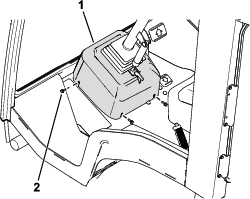
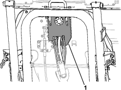
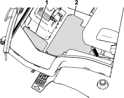
Installing the Steering Cover and Steering-Column Plugs
-
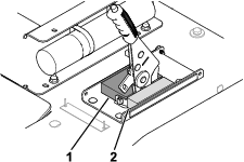
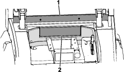
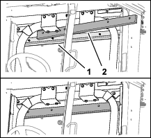
Remove the fasteners and lift the steering cover up out of the way (Figure 1).
Note: While you install the plugs/pads in this procedure, you can use string to secure the steering cover to the steering wheel.
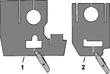
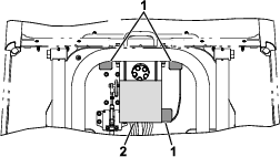
-
Use a utility knife to cut the upper and lower steering column plugs as shown in Figure 2.
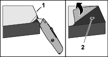
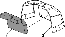
-
Remove the backing film from the pressure sensitive adhesive (PSA) side of the 2 plugs as shown in Figure 3.
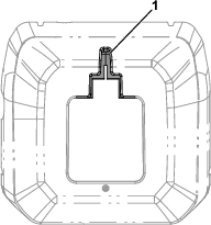
-
Install the upper steering plug (Figure 4).
-
Install the lower steering plug as shown in Figure 5. Ensure that it is adhered to upper steering plug.
-
Remove the backing film and install the steering pad (Figure 6).
-
Remove the backing film and install the 3 mounting-tab plugs over holes in floor pan. (Figure 6).
-
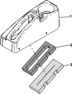
Remove the backing film and install the steering plug to the steering cover (Figure 7).
Figure 8 shows a top view of the installed steering plug in the steering cover.
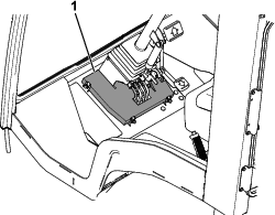
-
Install the steering cover (Figure 9).
Installing the Floor Pads
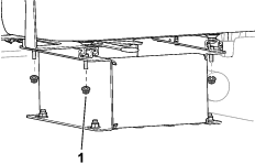
Removing the Seat
Perform the following steps to remove the seat from the seat base:
-
Remove the nuts that secures the seat to the seat base (Figure 12).
Note: Retain the nuts.
-
Remove any wire-harness connections from the seat.
-
Remove the seat from the seat base.
-
Note the position of the mounted seat to the seat base, as the seat needs to be re-installed in the same holes.
-
To install the seat pads (steps 1 through 3), have an assistant hold the seat above the seat base.
-
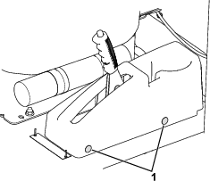
Installing the Brake Cover and Plugs
-
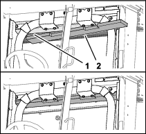
Remove the push-in fasteners that secure the brake cover to the floor (Figure 13).
-
Left side of the brake cover: Cut the plugs.
-
Right side of the brake cover: Pull the plugs out of the cover and retain the plugs.
-
-
Remove the brake cover.
-
If the optional USB charging kit is installed, perform the following steps:
-
Disconnect the 2 wire terminals from the USB port in the brake cover.
-
Remove the USB port from the brake cover.
-
-
Remove the backing film and install the brake plugs (Figure 14).
-
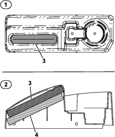
Remove the backing film from the top of the upper brake-cover foam, and install it to the brake cover (Figure 15).
Figure 16 shows a top and cutaway (side) view of the foam installed in the cover.
-
Remove the backing film from the bottom side of the upper brake-cover foam (Figure 15).
-
Install the lower brake-cover foam onto the upper brake-cover foam (Figure 15 and Figure 16).
-
If the optional USB charging kit is installed, perform the following steps:
-
Install the USB port into the brake cover.
-
Connect the 2 wire terminals of the machine harness to the USB port.
-
-
Install the brake cover with the 2 previously removed push-in fasteners (Figure 13).
Installing the Firewall Pads
Installing the Seat Pads
Installing the Corner Pads
Remove the backing film and install the corner pads as shown in Figure 21.
Installing the ROPS Plugs
Place the ROPS plugs into the ROPS tubes (Figure 22).
Installing the Upper-Frame Components
Parts needed for this procedure:
| Rear-pillar pad | 2 |
| Left door-side pad | 1 |
| Right door-side pad | 1 |
| Upper-ceiling pad | 1 |
| Lower-ceiling pad | 1 |
| Mount-panel pad | 2 |
| Left rear-pillar cover | 1 |
| Right rear-pillar cover | 1 |
| Left sound-dampening panel | 1 |
| Right sound-dampening panel | 1 |
| Left outer-pillar pad | 1 |
| Right outer-pillar pad | 1 |
Installing the Side-Panel Pads
-
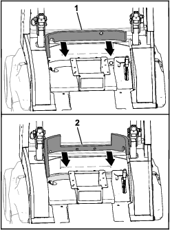
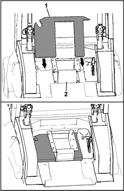
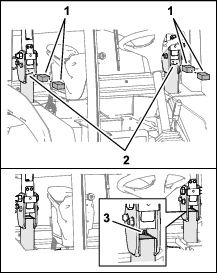
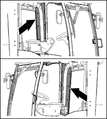
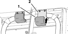
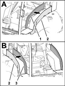
Remove the cab rear-side covers (Figure 23 and Figure 24).
Note: Retain the bolts.
-
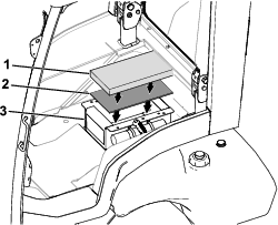
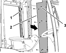
Install the rear-pillar pads over the hoses and wire harness (Figure 25).
-
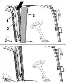
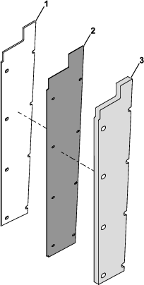
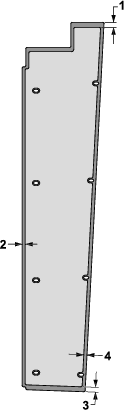
Remove the backing film and assemble the sound-dampening panels and the outer-pillar pads to the rear-pillar covers as shown in Figure 26 and Figure 27.
Figure 27 shows the proper dimensions for installing the outer-pillar pads and sound-dampening panels to the rear-pillar covers.
-
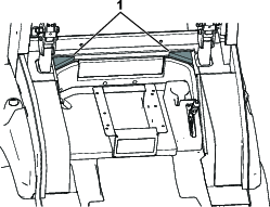
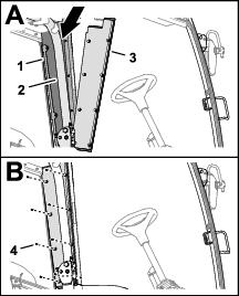
Use the previously-removed bolts to install the rear-pillar-cover assembly (i.e., the outer-pillar pads, rear-pillar covers, and sound-dampening panels) to the mount-panel brackets (Figure 28).
Install the assembly so that the outer-pillar pad is facing towards the operator.
Installing the Ceiling Pads
Installing the Door-Side Pads
Remove the backing film and install the door-side pads as shown in Figure 32.
Install the Mount-Panel Pads
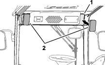
Remove the backing film and install the mount-panel pads to the sides of the cab control panel as shown in Figure 33.
Finishing Installing the Kit
Installing the Seat
-
Use the previously removed nuts to secure the seat to the seat base.
The seat should be installed in the same holes that you removed the hardware from in Removing the Seat.
-
Install any previously disconnected wire-harness connections to the seat.
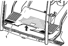
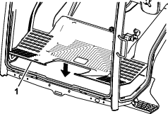
Installing the Rubber Floor Mat
Assemble the rubber floor mat to the floor of the machine (Figure 35).
Connecting the Battery
Connect the battery; refer to the electrical system maintenance section in the Operator’s Manual for your machine.