Important: Before installing the mid-mount toolbar system, you should obtain one of the toolbars available for use with the system. For more information, contact an authorized Toro distributor.
Setup
Preparing for Installation
Note: If you are installing tool bar 08733 or 08736, install the pivot tube brackets supplied with those tool bars instead of the ones supplied with this attachment. Refer to the installation instructions for 08733 or 08736 for more information.
Note: When installing a front manual blade in conjunction with a midmount toolbar system, install the midmount toolbar system first.
-
Park the traction unit on a level surface and engage the parking brake.
-
Move the throttle switch to the low-idle position, lower the attachment, and ensure that the traction is in neutral.
-
Shut off the engine, remove the key, wait for all moving parts to stop, and allow all components to cool.
Installing the Scarifier Lift-handle Assembly
Parts needed for this procedure:
| Bolt (5/16 x 2-1/4 inches) | 2 |
| Nut (5/16 inch) | 2 |
| Scarifier lift-handle assembly | 1 |
| Bolt (1/2 x 3-1/4 inches) | 2 |
| Thin locknut (1/2 inch) | 2 |
| Detent plate | 1 |
| Knob | 1 |
-
Lift the rear of the machine onto jack stands and remove the rear wheels; refer to your machine’s Operator’s Manual.
Note: Place the jack stands under the rear wheel motor mounts; refer to your machine’s Operator’s Manual.
-
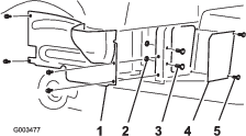
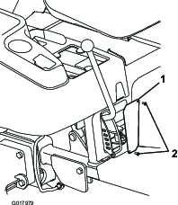
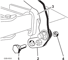
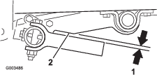
Remove the 4 flange-head screws that secure the right-hand wheel shroud to the frame (Figure 1).
-
Remove and retain the shroud.
Note: If a Manual Blade (Model 08714) is installed on the machine, remove the right blade-mounting bracket before installing the lift arm assembly.
-
Remove the 2 screws, 2 bolts, 2 washers and 2 nuts that secure the screen panel to the frame and retain the washers for later installation (Figure 1).
Note: You may discard the screen panel, bolts, screws, and nuts.
-
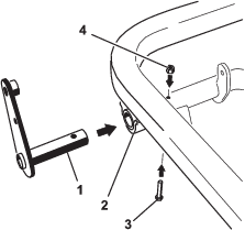
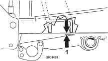
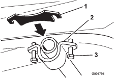
Install the mounting bracket of the scarifier lift-handle assembly to the right footrest tubes with 2 bolts (1/2 x 3-1/4 inch) and thin locknuts (1/2 inch), as shown in Figure 2.
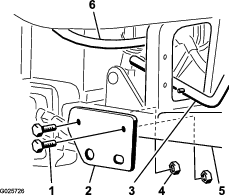
Note: Ensure that the bolt heads are positioned to the outside and that the thin locknuts are used.
Important: There are both thick and thin locknuts in the loose parts. Use the thin locknuts for this step. The thick locknuts cannot lock on here and will eventually fall off.
Note: The handle assembly is installed through the bottom of the traction unit by guiding the handle up through the opening made by removing the screen panel.
Note: Do not disassemble the handle assembly to install it into the traction unit.
-
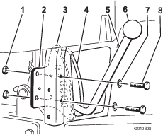
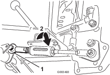
Insert the detent plate onto the scarifier lift handle.
Note: The handle should pass between the detent plate and the handle guide (Figure 3).
-
Install the detent plate to the back of the right rear vertical frame tube with 2 bolts (5/16 x 2-1/4 inch), the 2 washers removed in step 4, and 2 locknuts (5/16 inch). Position the parts as shown in Figure 3.)
-
Thread the knob onto the lift handle (Figure 3).
-
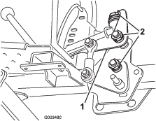
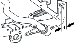
Ensure that the lift handle moves the full range of motion through the detent plate and that it locks into place at each detent location.
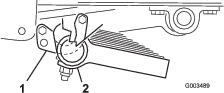
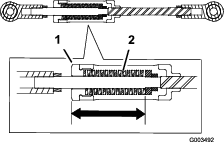
Note: If the lift handle is too loose or too tight, tighten or loosen the locknuts on the handle lift pivot (Figure 4).
-
Check the clearance between the lift handle assembly and the hydraulic lines.
Note: There must be a minimum clearance of 3 mm (1/8 inch) between the hydraulic line and the lift handle assembly. Gently position the hydraulic line as required (Figure 2).
Installing the Pivot Tube and the Tension Spring
Parts needed for this procedure:
| Pivot tube | 1 |
| Extension spring | 1 |
| Spring rod | 1 |
| Pivot tube bracket | 2 |
| Bolt (3/8 x 3 inches) | 4 |
| Locknut (3/8 inch) | 6 |
| Spring bracket | 1 |
| Bolt (3/8 x 2-3/4 inches) | 1 |
Note: If you are installing tool bar 08733 or 08736, install the pivot tube brackets supplied with those tool bars instead of the ones supplied with this attachment. Refer to the installation instructions for 08733 or 08736 for more information.
-
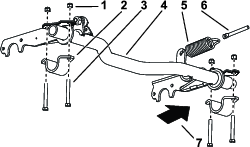
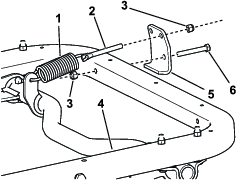
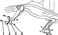
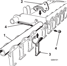
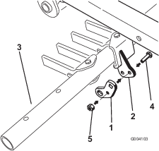
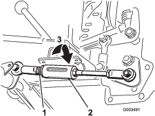
Connect the extension spring to the spring lever on the pivot tube and to the spring rod (Figure 5).
-
Loosely install the pivot tube bracket onto the right side (Figure 5).
-
Slide the right-hand side of the pivot tube into the right side pivot tube bracket (Figure 5).
-
Insert the spring rod into the hole in the spring bracket, and loosely secure it with a locknut (3/8 inch).
Note: Position the spring rod as shown in Figure 6.
-
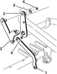
Raise the left-hand side of the pivot tube to the frame and install it with a pivot tube bracket, 2 bolts (3/8 x 3 inch), and 2 locknuts (3/8 inch) (Figure 5).
-
Mount the spring bracket to the front frame tube with a bolt (3/8 x 2-3/4 inch) and a locknut (3/8 inch).
Note: Position the spring bracket as shown in Figure 6.
-
Tighten all fasteners, but do not tighten the locknut that secure the spring rod at this time.
Installing the Adjustable Rod Assembly
Parts needed for this procedure:
| Adjustable rod assembly | 1 |
| Bolt (1/2 x 1-1/2 inches) | 1 |
| Locknut (1/2 inch) | 2 |
-
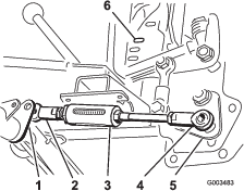
Position the ball joint of the short end of the adjustable rod assembly to the right of the adjustable rod lever on the pivot tube (Figure 7).
-
Move the lift handle to the second detent position from the top.
-
Place the ball joint on the long end of the adjustable rod assembly over the stud on the bottom on the lift handle assembly and loosely secure it with a locknut (1/2 inch) (Figure 7).
Note: You can move the pivot tube up or down in its brackets to gain clearance for mounting the adjustable rod.
-
Move the lift handle all the way downward to the bottom detent position.
-
Move the ball joint on the short end of the adjustable rod around the adjustable rod lever on the pivot tube until it is on the left side of the rod lever.
Note: You can move the pivot tube up or down in its brackets to gain clearance for mounting the adjustable rod.
-
Move the lift handle until the hole in the ball joint aligns with the hole on the right-side of the adjustable rod lever on the pivot tube, and secure the rod to the lever with a bolt (1/2 x 1-1/2 inches) and a locknut (1/2 inch) as shown in Figure 8.
-
Tighten the fasteners.
Installing the Screen Panel and Saddles
Parts needed for this procedure:
| Screen panel | 1 |
| HWH screw (#10 x 1/2 inch) | 2 |
| Right-hand saddle assembly | 1 |
| Left-hand saddle assembly | 1 |
| Bolt (5/16 x 1 inch) | 4 |
| Locknut (5/16 inch) | 4 |
Note: If you removed the manual plow, install it at this time.
-
Install the new screen panel to the back side of the frame opening with 2 HWH screws (#10 x 1/2 inch) (Figure 9).
-
Loosely attach the rear of a saddle assembly to each lift arm with a bolt (5/16 x 1 inch) and a locknut (5/16 inch).
Note: The saddle stud should point inward (Figure 10).
Note: Position the saddles as shown in Figure 10.
Installing a Toolbar
Parts needed for this procedure:
| Toolbar (sold separately) | 1 |
Important: If you are installing tool bar 08733 or 08736, skip this procedure and install it using the instructions provided with that toolbar. Once installed, go to Installing the Toolbar Lift Pedal in these instructions.
Note: If your toolbar comes without the pivot bracket installed, install it to the fourth tooth from the left as shown in Figure 11, and tighten the bolt and nut so that the bracket and tooth are secure before proceeding.
-
Position each end of the attachment tube onto the saddles.
Note: The cutting edges of the tines should point forward.
-
Move the lift handle to the middle position.
-
Secure the front of each saddle to the tube assembly with a bolt (5/16 x 1 inch) and a locknut (5/16 inch) (Figure 12).
Installing the Toolbar Lift Pedal
Parts needed for this procedure:
| Lever assembly | 1 |
| Bolt (5/16 x 2 inches) | 1 |
| Locknut (5/16 inch) | 3 |
| Pivot tab | 1 |
| Toolbar link | 1 |
| Carriage bolt (3/8 x 1-1/4 inches) | 1 |
| Spacer | 1 |
| Washer (1 inch) | 1 |
| Locknut (3/8 inch) | 1 |
| Pedal lever assembly | 1 |
| Retaining ring | 2 |
| Washer (7/8 inch) | 1 |
| Bolt (5/16 x 1 inch) | 1 |
| Eccentric bolt | 1 |
-
Slide the post on the lever assembly into the left end of the pivot tube, and secure it with a bolt (5/16 x 2 inches) and a locknut (5/16 inch) through the pivot tube (Figure 13).
Note: You may need to thread the bolt through the pivot tube and the lever assembly.
-
Loosely install the center hole of the pivot tab to the pivot bracket on the toolbar using a bolt (5/16 x 1 inch) and a locknut (5/16 inch) (Figure 14).
-
Slide the end of the toolbar link over the short post on the pedal lever assembly, and secure it with a retaining ring (Figure 15).
-
Install the post on the other end of the pedal lever assembly through the top of the lever assembly, and secure it using a washer (7/8 inch) and a retaining ring (Figure 15).
-
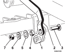
With the lift pedal assembly knee bent upwards, install the square hole on the pivot tab to the end of the toolbar link using a carriage bolt (3/8 x 1-1/4 inches), a spacer, a washer (1 inch), a washer (13/16 inch), and a locknut (3/8 inch) as shown in Figure 16.
-
Install the eccentric bolt through the bottom of the pivot tab and the pivot bracket, and secure it using a locknut (5/16 inch) as shown in Figure 17.
Adjusting the Pivot Spring Tension and the Adjustable Rod Assembly
-
Position the lift handle in the top detent position.
-
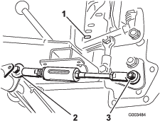
Measure the distance between the traction unit frame and the pivot tube as shown in Figure 18.
If the clearance is not between 0.06 to 0.18 inch, adjust the adjustable rod as follows:
-
Remove the bolt and nut that secures the rod to the pivot tube (Figure 19).
-
Rotate the ball joint shown in Figure 19 to change the length of the rod as follows:
-
To increase the gap, shorten the rod.
-
To decrease the gap, lengthen the rod.
-
-
Install the rod with the bolt and the locknut, and test the clearance again.
-
Repeat this procedure until the gap is correct.
-
-
Tighten the locknuts that secure the spring rod until 1/4 to 1/2 inch (6 mm to 13 mm) of the threads are showing to apply tension to the spring (Figure 20).
Note: Adjusting the spring rod will vary the lift effort of the system; the longer the bolt ends, the easier it will be to lift the toolbar. Adjust the springs so that the lift force is comfortable. The greater the tension on the assist spring, the less ground pressure there will be on the toolbar.
-
Install the right-hand wheel shroud.
-
Install the rear wheels and remove the jack stands from under the rear of the machine; refer to your machine’s Operator’s Manual.
Adjusting the Toolbar Transport Height
-
Position the lift handle to the transport position (upper most notch).
-
Rotate the eccentric bolt either direction until the toolbar tines are parallel to the notch in the lift arm (Figure 17 and Figure 21).
Important: The eccentric bolt will not rotate 360 degrees. When it stops, do not attempt to force it further or you will damage it. Instead, rotate it back the other direction.
-
Torque the center pivot bolt (item 4 in Figure 13) to 175 to 225 inch-lb (20 to 25 N⋅m).
-
Tighten the nut that secures the eccentric bolt until it is secure, but do not over-tighten it.
-
Test the operation of the attachment.
Leveling the Toolbar
Parts needed for this procedure:
| Shim (Part No. 110-7379) | 1 |
| Shim (Part No. 110-7380) | 1 |
| Shim (Part No. 110-7381) | 1 |
Once the toolbar has been installed and the fasteners are tightened, use the following procedure to verify that the toolbar teeth are level:
-
Park the machine on a level surface.
-
Check the pressure of all tires and ensure that they are equal. Refer to the Operator’s Manual for more information on checking the tire pressure.
-
Lower the toolbar until the teeth just begin to make contact with the ground.
-
If the teeth of the toolbar contact the ground evenly, the toolbar is level.
Note: If the teeth on one side of the toolbar contacts the ground before the other side, level the toolbar. Continue leveling by following the remainder of this procedure.
-
Measure the gap from the toolbar teeth to the ground on the side that requires leveling, then use the following table to determine which shim to install based on the gap measurement:
Shim pack (Thickness in inches) Change in Tooth height (inches) on Outside Edge 110-7379 (.0747 inches) 1/8 inch 110-7381 (1345 inches) 1/4 inch 110-7379 and 110-7381 (.2094 inches) 3/8 inch 110-7380 (.25 inches) 7/16 inch 110-7379 and 110-7380 (.3247 inches) 9/16 inch -
Loosen the bolts that secure the pivot tube bracket to create an opening between the frame and the pivot tube bracket (Figure 22).
Note: Installing the shim may require that you remove the lift pedal to access pivot tube bracket. Refer to Installing the Toolbar Lift Pedal.
-
Install the shim(s) and tighten all fasteners.
-
Verify that the toolbar is now level. If not, adjust it as needed.
Reading and Storing the Documentation
-
Read the documentation.
-
Store the documentation in a safe place.
Operation
-
To lower the toolbar, move the lift handle to the left, lower it, and then slide it to the right into the desired detent position.
-
To raise the toolbar, move the lift handle to the left, raise it, and then slide it to the right into the desired detent position.
-
To raise and lock the toolbar into the transport position, move the lift handle to the highest position and press the toolbar lift pedal down.
-
To release the toolbar from the transport position, move the lift handle to a lower position.
Note: If you use the scarifier tool bar, rotate the teeth to increase the usable life of the teeth.
Note: To obtain the desired operating position, you may need to first lower the toolbar beyond your desired position, and then raise it back up.
-
During operation, you can lower the toolbar into position by backing the machine up slowly while setting the toolbar to the desired depth. Once the toolbar is in the desired position, drive forward. The teeth will make contact with the ground, pulling the toolbar into the engaged position.
Adjusting the Downward Toolbar Pressure
To adjust the amount of downward pressure exerted on the ground by the tool, adjust the spring tension of the adjustable rod. Using a 3/4-inch wrench, rotate the spring sleeve casting on the adjustable rod in the right-hand thread direction to increase the downward pressure or the opposite direction to decrease the downward pressure (Figure 23).
Note: This does not change the adjustable rod setting performed in the Adjusting the Pivot Spring Tension and the Adjustable Rod Assembly procedure.
Use the following table and figure as a guide for adjusting the downward toolbar pressure (Figure 24).
| Spring Force Chart | |
| Dimension (inches) | Force (pounds) |
| 3.00 | 238 |
| 2.88 | 335 |
| 2.75 | 430 |
| 2.62 | 526 |
| 2.50 | 623 |
Troubleshooting
| Problem | Possible Cause | Corrective Action |
|---|---|---|
| Lifting the attachment requires excessive force. |
|
|
| The handle does not lock into the detent slots on the detent plate. |
|
|
| The toolbar does not rotate high enough. |
|
|
| The downward pressure of the attachment is too light. |
|
|
| There is uneven ground contact when turning the machine. |
|
|
| The machine stops when it hits an obstacle. |
|
|
| The toolbar teeth are not level. |
|
|