Installation
Preparing the Machine
-
Park the machine on a level surface.
-
Engage the parking brake.
-
Shut off the machine and remove the key.

Removing an Existing Plastic Cargo Bed
If your machine is not equipped with a plastic cargo, you can skip to the next installation procedure.
-
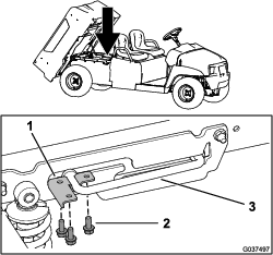
Using an overhead hoist, raise the plastic cargo bed.
-
Remove the 3 flange-head bolts (5/16 x 3/4 inch) and prop rod U-bracket from the prop rod (Figure 2).
Note: Retain the hardware if you want to install the plastic cargo bed in the future.
-
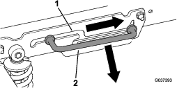
Slide the prop rod forward out of the detent slot and remove the prop rod (Figure 3).
-
Using an overhead hoist, lower the cargo bed.
-
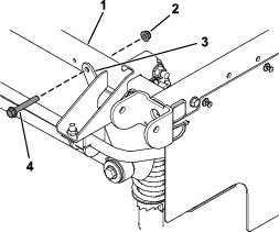
Remove the 2 pivot bolts (1/2 x 4-1/2 inches) and 2 locknuts (1/2 inch) from the pivot bracket located at the rear of the machine (Figure 4).
Note: Retain the hardware if you want to install the plastic cargo bed in the future.
-
Release the cargo-bed lever and raise the cargo bed using an overhead hoist.
Installing the Lift Bracket
Parts needed for this procedure:
| Lift bracket | 1 |
| Flange-head bolt (3/8 x 2-1/2 inches) | 2 |
| Locknut (3/8 inch) | 2 |
-
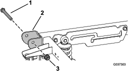
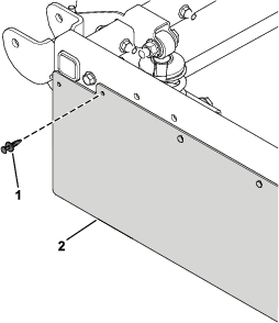
Remove the existing flange-head bolt and locknut from the right stabilizer bracket and rear frame tube (Figure 5).
-
Remove 1 plastic push rivet from the side panel (Figure 6).
Retain the plastic push rivet for later installation.
-
Pull down the corner of the side panel (Figure 6).
-
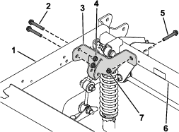
Secure the lift bracket to the rear and right frame tubes using the previously removed flange-head bolt and locknut and new 2 flange-head bolts (3/8 x 2-1/2 inches) and 2 locknuts (3/8 inch) as shown in Figure 7.
-
Torque the previously removed flange-head bolt and new 2 flange-head bolts (3/8 x 2-1/2 inches) to 41 N∙m (30 ft-lb).
-
Install the previously removed plastic push rivet (Figure 6).
Installing the Flat Bed Assembly
Parts needed for this procedure:
| Flat bed assembly | 1 |
| Flange-head bolt (1/2 x 4-1/2 inches) | 2 |
| Locknut (1/2 inch) | 2 |
-
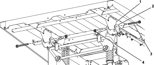
Move the flat bed rearward until the pivot-bracket assembly is aligned over the rear-frame channel.
-
Carefully lower the flat bed until the holes in the pivot brackets align with the mounting holes in the flat bed supports (Figure 8).
-
Secure the flat bed assembly to the pivot brackets using the 2 flange-head bolts (1/2 x 4-1/2 inches) and 2 locknuts (1/2 inch) as shown in Figure 8.
-
Torque the 2 locknuts (1/2 inch) to 16 to 19 N∙m (140 to 170 in-lb).
Installing the Gas Spring
Parts needed for this procedure:
| Gas spring | 1 |
| Clevis pin | 2 |
| Hairpin cotter | 2 |
| Spacer | 4 |
-
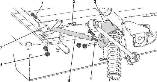
Lift the flat bed assembly.
-
With the body side of the gas spring oriented toward the flat bed, secure the gas spring to the lift bracket using 2 clevis pins, 4 spacers, and 2 hairpin cotters (Figure 9).
Ensure that you use the inner set of holes on the flat bed when securing the gas spring as shown in Figure 9.
Adjusting the Cargo Bed Latches
If the cargo bed latch is out of adjustment, the cargo bed vibrates up and down as you drive the machine. You can adjust the latch posts to make the latches hold the cargo bed securely to the chassis.
-
Verify that the cargo bed is latching.
Note: If the cargo bed does not latch, the bed-latch striker is likely too low. If the cargo bed latches, but vibrates up and down as you drive, the bed-latch striker is likely too high.
-
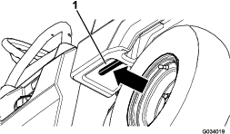
Pull on the lever on the left, inside of the cargo bed toward you and lift the cargo bed up (Figure 10).
-
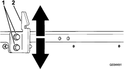
Loosen the 2 bolts on the bed-latch striker and move the striker up or down, depending on if the striker is too high or too low (Figure 11).
-
Tighten the 2 bolts on the bed-latch striker (Figure 11).
-
Verify that the adjustment is correct by latching the cargo bed several times.