Safety
Safety and Instructional Decals
 |
Safety decals and instructions are easily visible to the operator and are located near any area of potential danger. Replace any decal that is damaged or missing. |
Installation
Note: Determine the left and right sides of the machine from the normal operating position.
Preparing the Machine
-
Park the machine on a level surface.
-
Engage the parking brake.
-
Lower the loader arms.
-
Shut off the engine and remove the key.
-
Open the hood and secure the prop rod.
-
Turn the battery-disconnect switch to the OFF position.
Accessing Internal Components
-
Use a nylon strap to secure the hood to a reference bar on the control panel.
-
Remove the prop rod from the hood.
-
Open the rear-access cover and secure it open using a nylon strap.
-
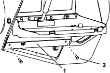
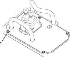
Remove the cover plate.
-
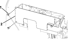
Remove the bolt and washer to release the rubber baffle.
-
Remove the bottom plate.
Replacing the Traction Valve
Parts needed for this procedure:
| Traction valve | 1 |
| Swivel elbow fitting | 2 |
| Straight fitting | 2 |
Removing the Valve
-
If the machine has a test port, remove the test port and elbow fitting from the right side of the traction valve. Discard the elbow fitting.
-
Label the traction valve hoses with their port locations.
-
Disconnect the hose fittings from the valve.
-
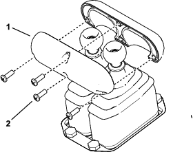
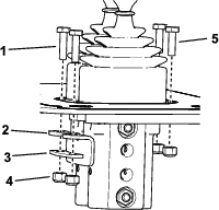
Remove the handle from traction valve.
-
Remove the fasteners from the cover panel.
-
Remove the fasteners, rubber cover, and clamp plate securing the valve to the cover plate.
-
Remove the valve.
Installing the Valve
-
Secure the new traction valve to the cover panel.
-
Secure the cover panel to the control panel.
-
Install the 2 handle halves to the traction valve, positioning the screw heads toward the operator position.
Installing the Traction Valve Hoses and Fittings
-
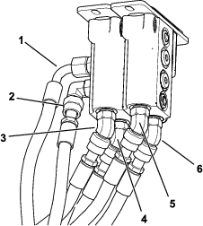
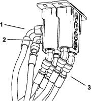
Install the 4 lower hoses to their labeled locations; angle the fittings toward the 10 o’clock position (toward the front, left).
-
Install the hoses to the upper and lower left ports; angle the lower fitting toward the 5 o’clock position.
-
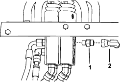
Install a straight fitting to the upper right port (T).
-
Install the elbow fitting to the straight fitting and point it forward.
-
If you previously removed a test port, install the test port to a new swivel fitting and install a straight fitting and the elbow fitting to the lower right port (P).
-
Torque the straight and 45-degree fittings to 12.2 to 14.9 N∙m (9 to 11 ft-lb).
-
Torque the swivel fittings and test port (if applicable) to 24.4 to 29.8 N∙m (18 to 22 ft-lb).
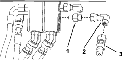
Installing the Traction Valve Fittings
Parts needed for this procedure:
| Swivel fitting | 1 |
| Straight fitting | 1 |
-
Install a straight fitting and elbow fitting to the upper right port of the traction valve.
-
Torque the straight fitting to 12.2 to 14.9 N∙m (9 to 11 ft-lb).
-
Torque the swivel fitting to 24.4 to 29.8 N∙m (18 to 22 ft-lb).
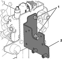
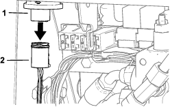
Installing the Solenoid Valve
Parts needed for this procedure:
| Solenoid valve bracket | 1 |
| Elbow fitting | 3 |
| Solenoid valve | 1 |
| Bolt (1/4 x 2 inches) | 2 |
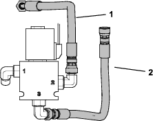
| Hose—26 cm (10-1/4 inch) length | 1 |
| Hose—31 cm (12-1/4 inch) length | 1 |
-
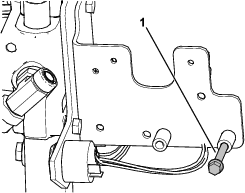
Remove the hose that extends from the tee fitting on the detent valve to the T1 port on the loader valve.
-
Remove the radiator hose from the detent valve.
-
Remove the locknuts securing the detent valve to the bracket.
-
Use the locknuts you removed to install the solenoid valve bracket.
-
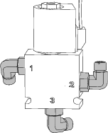
Install 3 elbow fittings on the solenoid valve. Torque them to 12 to 15 N∙m (9 to 11 ft-lb).
Note: For machines without a Low Flow Kit, rotate the fittings at ports 1 and 3 approximately 30° toward the rear.For machines with a Low Flow Kit, rotate the fittings toward the front.
-
Loosely install hoses on ports 2 and 3.
-
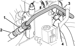
Loosen the upper left hose on the traction valve. Swivel it away to improve access to the charge-pressure hose.
-
Remove the charge-pressure hose from the lower left port and install it to port 1 on the solenoid valve.
-
Install 1 bolt (1/4 x 2 inches) to the left side of the solenoid bracket.
-
Connect the hose from port 2 on the solenoid valve to the upper right fitting on the traction-control valve.
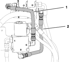
-
Connect the hose from port 3 on the solenoid valve to the lower left fitting on the traction-control valve.
-
Torque the hoses on the valve fittings and the hose loosened in step 10 to 24.4 to 29.8 N∙m (18 to 22 ft-lb).
-
Place the solenoid valve onto the bolt, then secure it with the second bolt.
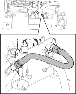
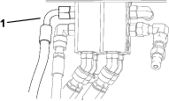
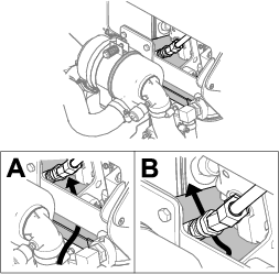
Connecting the Hydraulic Tube
Parts needed for this procedure:
| Tube | 1 |
-
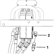
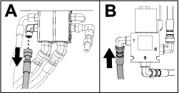
Loosen the nut on the detent valve tee fitting.
-
Loosely install the tube to the T1 port on the loader valve.
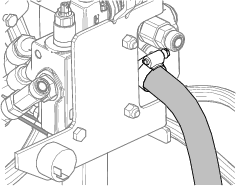
-
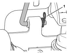
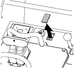
Push down the hose shown in Figure 27 to rotate the tee fitting to align it with the tube.
-
Install the tube to the fitting.
-
Torque both ends of the tube to 50.2 to 63.7 N∙m (37 to 47 ft-lb).
-
Torque the nut on the tee fitting to 78.6 to 97.6 N∙m (58 to 72 ft-lb).
-
Install the radiator hose to the detent valve and tighten the hose clamp.
Cutting a Hole for the Switch
If your machine does not have a plug on the control panel, you must cut a hole to install the switch.
Warning
Using a drill without wearing eye protection may allow debris to enter the eye, causing personal injury.
When drilling, always wear eye protection.
-
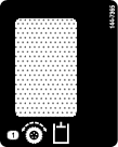
Using the dimensions shown, mark a 2.1 x 3.7 cm (0.83 x 1.45 inch) rectangle on the control panel.
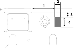
-
Drill a 3/8 inch hole in the center of the rectangle, then use a jigsaw to cut out the rectangle.
Important: Ensure that you do not cut through any wires or hoses beneath the control panel.
-
Remove any burrs around the edge of the hole.
Installing the Switch and Decal
Parts needed for this procedure:
| Switch | 1 |
| Decal | 1 |
-
Remove the plug (if applicable) from the control panel.
-
Clean around the hole with alcohol and a clean rag.
-
Remove the backing from the decal and install the decal.
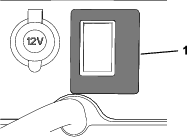
-
Install the switch.
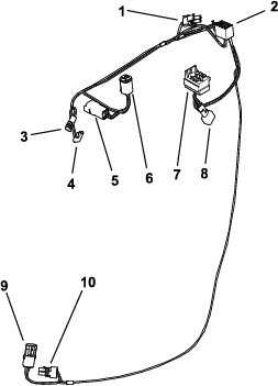
Routing the Wire Harness
Parts needed for this procedure:
| Wire harness | 1 |
| Self-tapping screw | 1 |
| Relay | 1 |
| Traction enable jumper harness | 1 |
| Cable tie | 2 |
Wire Harness Overview
Note: This kit contains 2 wire harnesses. Use the wire harness that fits the key switch to your machine and discard the other wire harness.
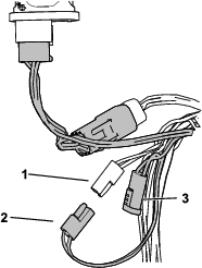
Installing the Upper Connectors
-
Route the upper portion of the wire harness between the rubber baffle and frame and behind the detent valve hydraulic hose.
-
Disconnect the machine wire harness from the key switch.
-
Connect the key switch connector to the key switch input (P03) on the kit wire harness.
-
Connect the key switch output (P04) to the key switch.
-
Locate the auxiliary connector on the machine wire harness and remove the cap.
Note: The connector is secured underneath the machine wire harness using a cable tie, near the key switch connector. If another connector is already plugged into it, unplug the connector and plug it into the auxiliary output connector (P07).
-
Connect the auxiliary input connector (P06) to the auxiliary connector on the machine wire harness.
-
Disconnect the wire harness from the audio alarm.
-
If the Low Flow Kit is installed on the machine, remove the audio alarm.
-
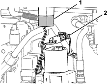
Route the traction relay, switch, and solenoid connectors under the alarm bracket.
-
Secure the wire harness for the traction relay connector to the solenoid bracket using the attached push-mount cable tie.
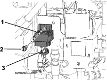
-
Secure the traction relay connector (P10) to the solenoid bracket using a self-tapping screw.
-
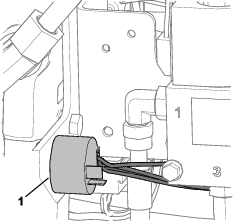
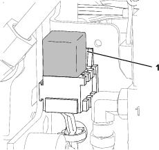
Install the relay.
-
Route the traction switch and solenoid valve connectors under the relay connector and between the solenoid bracket and valve fitting.
-
Connect the traction switch connector (P08) to the traction switch.
-
Connect the solenoid valve connector (P05) to the solenoid valve.
-
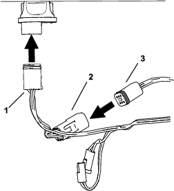
If the Low Flow Kit is installed on the machine, install the audio alarm.
-
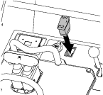
Connect the machine wire harness to the audio alarm (Figure 37).
-
Disconnect the traction valve connectors from the machine wire harness and move them out of the way.
Note: The traction valve connectors will remain disconnected after installing this kit.
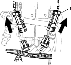
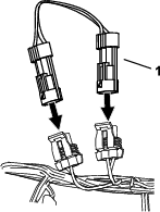
-
Install the jumper harness to the 2 machine wire harness connectors.
Installing the Lower Connectors
-
Raise the rear of the machine so that you can access beneath it. Support it using jackstands.
Note: Use jack stands rated for your machine. Refer to the Operator’s Manual for your machine to determine the weight.
Warning
Mechanical or hydraulic jacks may fail to support the machine and cause serious injury.
Use jack stands when supporting the machine.
-
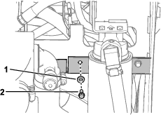
Route the parking brake connectors from the rubber baffle, behind the hydraulic filter, through the existing cable tie for the hydraulic hoses, and down to the left traction motor, following the hydraulic hoses.
-
Disconnect the parking brake switch from the machine wire harness.
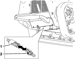
-
Plug the parking brake switch into the parking brake output (P02) on the kit wire harness.
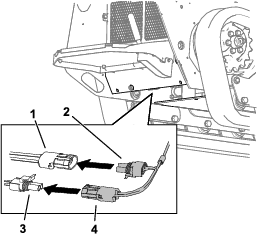
-
Plug the parking-brake switch connector on the machine wire harness to the parking brake input (P02) on the kit wire harness.
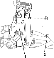
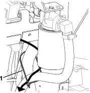
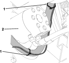
Securing the Wire Harness
Use cable ties to secure the wire harness above and below the left traction motor as shown.
Completing the Installation
-
Install the bottom plate.
-
Remove the jackstands and lower the machine to the ground.
-
Secure the rubber baffle.
-
Install the cover plate.
-
Install the prop rod.
-
Remove the strap and close the rear access cover.
-
Turn the battery-disconnect switch to the ON position.
-
Remove the strap and close the hood.
Operation
Using the Traction-Enable Switch
The traction control is automatically disabled when starting the machine. Toggle the traction-enable switch after starting the machine to use the traction control.