Note: Models 31900, 31901, 31902, and 31907 require the additional Power Harness Kit (Part No. 140-1559). Models with cabs do not use the Power Harness Kit.
Safety
Safety and Instructional Decals
 |
Safety decals and instructions are easily visible to the operator and are located near any area of potential danger. Replace any decal that is damaged or missing. |
Installation
Preparing the Machine
-
Park the machine on a level surface.
-
Shift to the NEUTRAL position.
-
Lower all attachments (if equipped).
-
Engage the parking brake.
-
Shut off the engine and remove the key.
-
Disconnect the battery; refer to your machine Operator’s Manual.
Installing the Clips, Speed Nuts, and Fuse Block
Parts needed for this procedure:
| Switch mount | 1 |
| Clip (1/4 inch) | 6 |
| Speed nut | 2 |
| Fuse mount plate | 1 |
| U-type speed nut | 4 |
| Fuse block | 1 |
| Screw (#10 x 3/4 inch) | 2 |
Installing the Switch Mount
Parts needed for this procedure:
| Mount bracket | 2 |
| Carriage bolt (1/4 x 2 inches) | 4 |
| Locknut (1/4 inch) | 2 |
| Hex-head screw (1/4 x 3/4 inch) | 2 |
| Flange nut (1/4 inch) | 2 |
| Flasher | 1 |
| Relay | 1 |
| Wire harness | 1 |
| Cable tie | 2 |
| Fuse cover | 1 |
| Thumb screw | 2 |
| Push nut | 2 |
| Decal | 1 |
| Screw (#10 x 3/8 inch) | 2 |
| Multi-function switch | 1 |
| Hole plug | 3 |
| Rocker switch | 1 |
| Control cover | 1 |
| Hex-head screw (1/4 x 3/4 inch) | 6 |
| Switch clip | 2 |
| Push rivet | 2 |
-
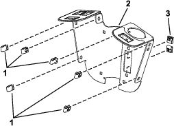
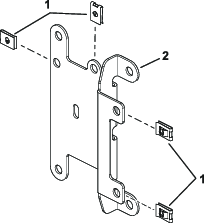
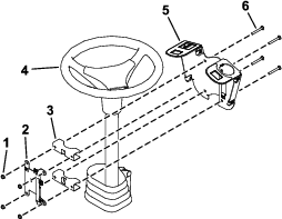
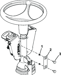
Loosely install the switch mount around the steering column using 4 carriage bolts (1/4 x 2 inches), 2 mounting brackets, fuse-mount plate, and 4 locknuts (1/4 inch) as shown in Figure 4.
-
Install the multi-function switch to the switch mount and secure it using the switch clips under the hole for the switch (Figure 5).
-
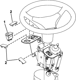
Install the rocker switch and hole plugs into the switch mount (Figure 6).
-
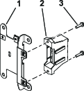
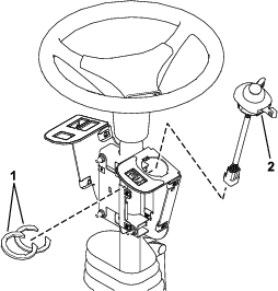
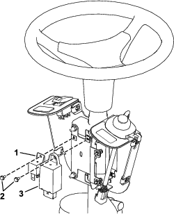
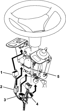
Install the flasher and relay to the fuse-mount plate using 2 screws (#10 x 3/8 inch) as shown in Figure 7.
-
Secure the flasher using a cable tie (Figure 8).
-
Plug the harness into the rocker switch and multi-function switch (Figure 8).
-
Plug the wire harness into the relay and flasher (Figure 8).
-
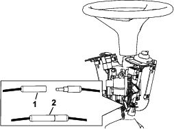
If the machine is used in North America, connect the bullet connectors as shown in Figure 9.
Note: Do not connect the bullet connectors if the machine is used outside of North America.This connection sets the flasher rate required for North America vs. non-North America road regulations.
-
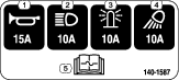
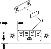
Apply the decal to the fuse cover as shown in Figure 10.
-
Install the fuse cover to the switch mount using 2 thumb screws and 2 push nuts (Figure 11).
Note: Ensure that the push nuts are installed on the inside of the fuse cover (Figure 11).
-
Adjust the control assembly so that the switches are accessible.
-
Tighten all the fasteners.
-
Install the control cover to the switch mount using 2 push rivets and 6 hex-head screws (1/4 x 3/4 inch) as shown in Figure 12.
Routing the Wire Harness
-
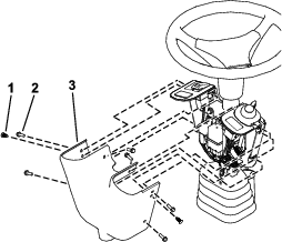
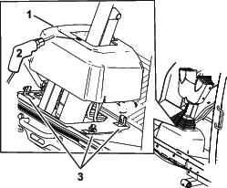
Loosen the bolts around the steering-column base (Figure 13)
-
Raise the base up and drill a 22 mm (7/8 inch) hole as shown in Figure 13.
-
Route the harness through the hole you drilled in the base.
-
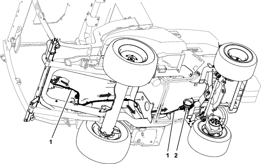
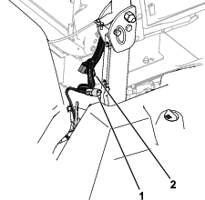
Route the control wire-harness connector (P05) to the right side of the machine (Figure 14).
-
Connect the harness.
-
For cab units:
Connect the control wire-harness connector labeled TO POWER HARNESS (P05) to the cab wire-harness connector labeled POD CONTROL HARNESS (P04); refer to Figure 15.
-
For ROPs units:
Note: Ensure the additional power harness kit (Part No. 140-1559) is installed.
Connect the control wire-harness connector labeled TO POWER HARNESS (P05) to power wire-harness connector labeled POD CONTROL HARNESS (P04); refer to Figure 15.
-
-
When optional horn or light kits are installed, connect the wire harness to the optional kits (Figure 14).
-
Connect the battery; refer to your machine Operator’s Manual.