Introduction
This kit is designed to help the operator monitor the flow at individual spray nozzles during turf sprayer application on well-maintained lawns in parks, golf courses, sports fields, and on commercial grounds. It is a dedicated attachment for a turf spray application vehicle and is intended to be used by professional, hired operators in commercial applications. Using this product for purposes other than its intended use could prove dangerous to you and bystanders.
Read this information carefully to learn how to operate and maintain your product properly and to avoid injury and product damage. You are responsible for operating the product properly and safely.
Visit www.Toro.com for product safety and operation training materials, accessory information, help finding a dealer, or to register your product.
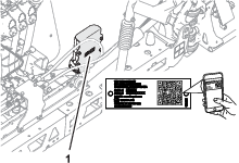
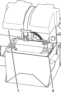
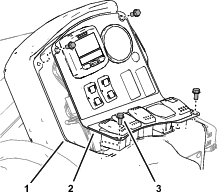
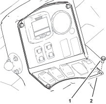
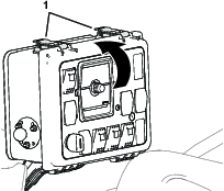
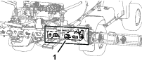
Whenever you need service, genuine Toro parts, or additional information, contact an Authorized Service Dealer or Toro Customer Service and have the model and serial numbers of your product ready. Figure 1 identifies the location of the model and serial numbers on the product. Write the numbers in the space provided.
Installation
Preparing the Machine
Caution
Chemicals are hazardous and can cause personal injury.
-
Read the directions on the chemical labels before handling the chemicals and follow all manufacturer recommendations and precautions.
-
Keep chemicals away from your skin. Should contact occur, wash the affected area thoroughly with soap and clean water.
-
Wear goggles and any other protective equipment recommended by the chemical manufacturer.
-
Park the machine on a level surface.
-
Move the traction pedal to the neutral position, or shift the transmission into the NEUTRAL position (manual) or the PARK position (automatic).
-
Engage the parking brake.
-
Shut off the engine and remove the key.
-
Wait for all movement to stop before leaving the operator’s seat.
-
Clean the sprayer; refer to Cleaning the Sprayer in the Operator’s Manual for the machine.
-
Allow the machine components to cool.
Disconnecting the Battery
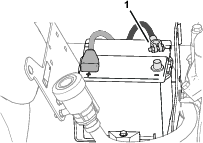
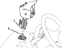
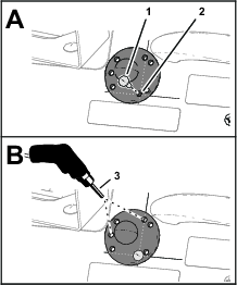
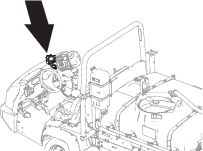
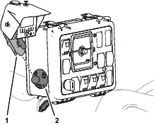
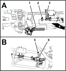
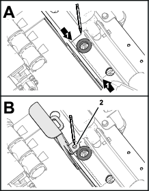
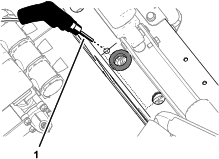
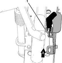
Removing the Negative Battery Cable
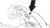
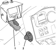
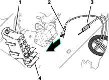
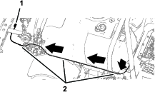
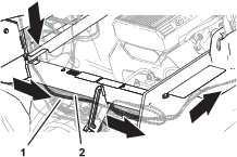
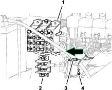
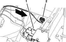
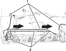
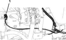
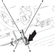
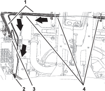
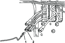
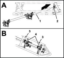
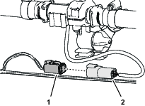
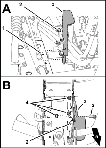
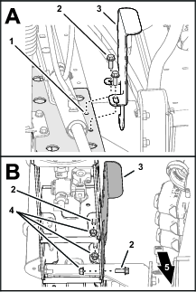
Remove the negative-battery cable from the battery (Figure 2).
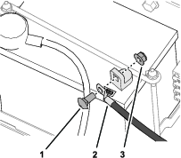
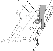
Removing the Negative Battery Cable
-
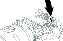
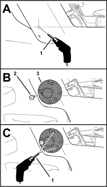
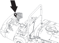
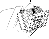
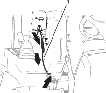
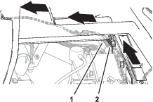
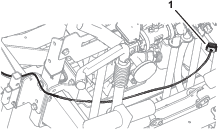
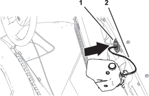
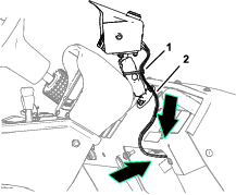
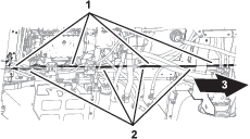
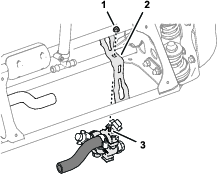
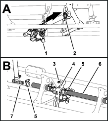
Tilt forward the operator’s seat.
-
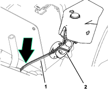
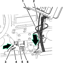
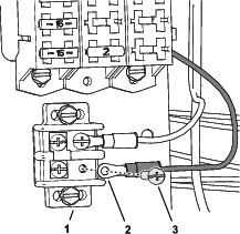
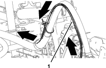
Remove the negative-battery cable from the battery (Figure 3).
-
Lower the operator’s seat.
Removing the Negative Battery Cable
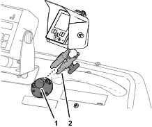
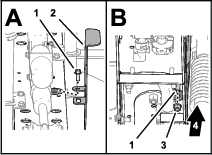
Installing the Display/Controller
Parts needed for this procedure:
| Ball mount | 1 |
| Carriage bolt (#10 x 7/8 inch) | 3 |
| Stiffener plate | 1 |
| Flange locknut (#10) | 3 |
| Display/controller, socket arm, and wire harness assembly | 1 |
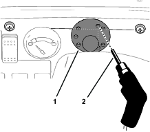
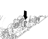
Marking the Hole Location
-
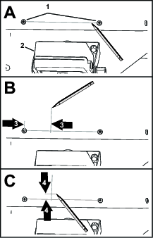
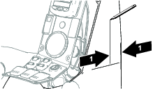
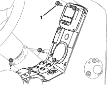
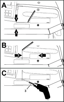
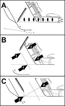
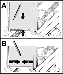
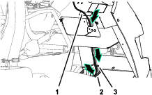
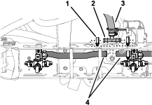
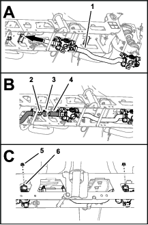
Forward of the spray monitor, draw a horizontal line between the Phillips-head screws that secure the hood (Figure 7).
-
Measure 57 mm (2-1/4 inches) from the left Phillips-head screw and along the line that you marked in step 1, and mark a vertical line 50 mm (2 inches) on the hood as shown in Figure 7.
-
Measure 10 mm (3/8 inch) from the line you marked in step 1 and mark a horizontal line on the hood as shown in Figure 7.
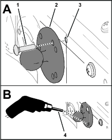
Drilling the Hood
-
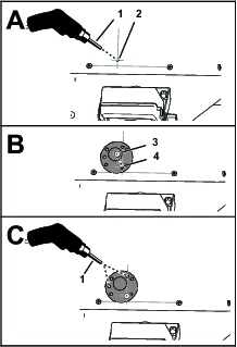
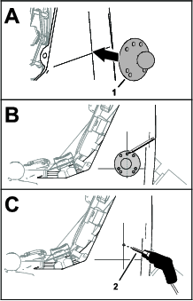
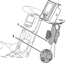
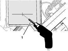
At the intersection lines, drill a hole (4 mm or 1/4 inch) in the hood (Figure 8).
-
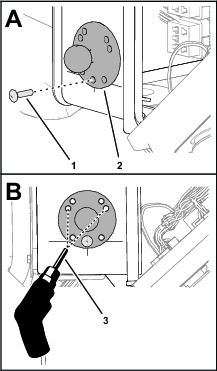
Align the hole in the ball mount with the hole in the hood and insert a carriage bolt (#10 x 7/8 inch) as shown in Figure 8.
-
Align the hole in the ball mount with the vertical line and use the ball mount as a template to drill a hole (4 mm or 1/4 inch) in the hood (Figure 8).
-
Align the hole in the ball mount with the hole in the hood and insert another carriage bolt (#10 x 7/8 inch).
-
Using the ball mount as a template, drill a hole (4 mm or 1/4 inch) in the hood (Figure 8).
-
Remove the ball mount and carriage bolts from the hood.
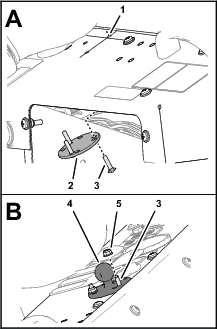
Assembling the Ball Mount and Display/Controller
-
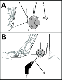
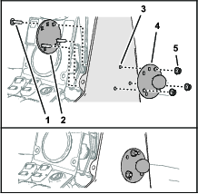
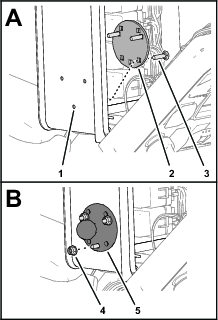
Assemble the 3 carriage bolts into the square opening in the stiffener plate as shown in Figure 9.
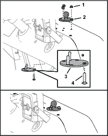
-
Assemble the carriage bolts and stiffener plate to the holes in the hood (Figure 9).
-
Assemble the ball mount onto the carriage bolts and secure the mount to the hood (Figure 9) with 3 flange locknuts (#10).
-
Assemble the socket arm of the display/controller onto the ball mount and tighten the thumbscrew of the arm (Figure 10).
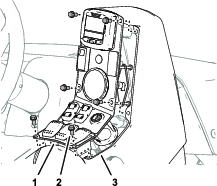
Accessing the Console
Remove the 6 flange-head screws that secure the switch panel to the console, and move the panel to provide access to the control console (Figure 11).
Marking the Hole Location
-
Mark a horizontal line across the side of the control console as shown in Figure 12.
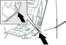
-
Measure 47 mm (1-5/8 inches) from the corner of the control console and along the line that you marked in step 1, and mark a vertical line 50 mm (2 inches) on the control console as shown in Figure 13.
-
Align the holes in the ball mount to the lines that you marked in steps 1 and 2 as shown in Figure 14.
-
Using the ball mount as a template, mark the hole location on the vertical line as shown in Figure 14.
-
At the mark that you made in step 4, drill a hole (4 mm or 1/4 inch) in the side of the control console (Figure 14).
Drilling the Console
-
Align the hole in the ball mount with the hole in the console and insert a carriage bolt (#10 x 7/8 inch) as shown in Figure 15.
-
Align the holes in the ball mount with the horizontal line, and using the ball mount as a template, drill a hole (4 mm or 1/4 inch) in the control console (Figure 15).
-
Align the hole in the ball mount with the hole in the control console and insert another carriage bolt (#10 x 7/8 inch).
-
Using the ball mount as a template, drill a hole (4 mm or 1/4 inch) in the control console (Figure 15).
-
Remove the ball mount and carriage bolts from the control console.
Assembling the Ball Mount and Display/Controller
-
Assemble the 3 carriage bolts into the square opening in the stiffener plate as shown in Figure 16.
-
Assemble the carriage bolts and stiffener plate to the holes in the control console (Figure 16).
-
Assemble the ball mount onto the carriage bolts and secure the mount to the control console (Figure 16) with 3 flange locknuts (#10).
-
Align the holes in the switch panel with the holes on the control console (Figure 17).
-
Secure the panel to the control console with the 6 flange-head screws (Figure 17) that you removed in Accessing the Console.
-
Assemble the socket arm of the display/controller onto the ball mount and tighten the thumbscrew of the arm (Figure 18).
Marking the Hole Location
-
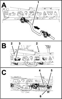
At the right of the spray monitor, measure 42 mm (1-5/8 inches) forward of the bend in the dash panel and mark a horizontal line across the dash panel as shown in Figure 20.
-
From the Phillips-head screw, measure 104 mm (3/8 inch) left and mark a vertical line 50 mm (2 inches) on the dash panel as shown in Figure 20.
-
At the intersection lines, drill a hole (4 mm or 1/4 inch) in the dash panel (Figure 20).
Drilling the Dash Panel
-
Align the hole in the ball mount with the hole in the dash and insert a carriage bolt (#10 x 7/8 inch) as shown in Figure 21.
-
Align the hole in the ball mount with the vertical line and use the ball mount as a template to drill a hole in the dash panel with a 6 mm (1/4 inch) drill bit (Figure 21).
-
Align the hole in the ball mount with the hole in the dash and insert another carriage bolt (#10 x 7/8 inch).
-
Using the ball mount as a template, drill a hole (4 mm or 1/4 inch) in the dash panel (Figure 21).
-
Remove the ball mount and carriage bolts from the dash panel.
Assembling the Ball Mount and Display/Controller
-
Assemble the 3 carriage bolts into the square opening in the stiffener plate as shown in Figure 22.
-
Assemble the carriage bolts and stiffener plate to the holes in the dash panel (Figure 22).
-
Assemble the ball mount onto the carriage bolts and secure the mount to the dash panel (Figure 22) with 3 flange locknuts (#10).
-
Assemble the socket arm of the display/controller onto the ball mount and tighten the thumbscrew of the arm (Figure 23).
Marking the Hole Location
-
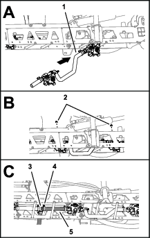
Above the fuel gauge, draw a horizontal line between the Phillips-head screws that secure the dash panel as shown in Figure 24.
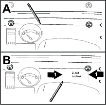
-
Measure 64 mm (2-1/2 inches) from the right Phillips-head screw and along the line that you marked in step 1, and mark a vertical line 50mm (2 inches) on the dash panel as shown in Figure 24.
Drilling the Dash Panel
-
Align the ball mount to the dash panel and the 2 vertical hole of the mount to the vertical line (Figure 25) that you marked in step 2 of Marking the Hole Location .
-
Using the ball mount as a template, drill the a upper hole (4 mm or 1/4 inch) in the dash panel as shown in Figure 25.
-
Align the hole in the ball mount with the hole in the dash panel and insert a carriage bolt (#10 x 7/8 inch) as shown in Figure 26.
-
Align the hole in the ball mount with the vertical line and use the ball mount as a template to drill a hole (4 mm or 1/4 inch) in the dash panel (Figure 26).
-
Insert another carriage bolt (#10 x 7/8 inch) through the holes in the ball mount and dash panel.
-
Using the ball mount as a template, drill a hole (4 mm or 1/4 inch) in the dash panel (Figure 26).
-
Remove the ball mount and carriage bolts from the dash panel.
Assembling the Ball Mount and Display/Controller
-
Assemble the 3 carriage bolts into the square opening in the stiffener plate as shown in Figure 27.
-
Assemble the carriage bolts and stiffener plate to the holes in the dash panel (Figure 27).
-
Assemble the ball mount onto the carriage bolts and secure the mount to the dash panel (Figure 27) with 3 flange locknuts (#10).
-
Assemble the socket arm of the display/controller onto the ball mount and tighten the thumbscrew of the arm (Figure 28).

Accessing the Control Console
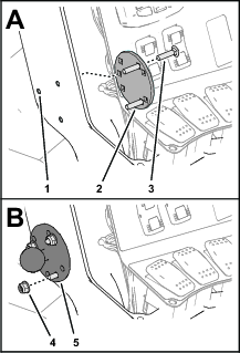
Remove the 4 flange-head screws that secure the console panel to the control console, and move the panel to provide access to the console (Figure 30).
Marking the Hole Location
-
Mark a horizontal line across the side of the control console as shown in Figure 31.
-
Mark a parallel line 30 mm (1-1/8 inches) from the face of the control console as shown in Figure 31.
-
Mark an intersecting vertical line 65 mm (2-1/2 inches) from the face of the control console as shown in Figure 31.
Note: Ensure that the line intersects the line that you marked in step 1.
Drilling the Console
-
At the intersection lines you marked in steps 1 and 3, drill a hole (4 mm or 1/4 inch) in the control console (Figure 32).
-
Align the hole in the ball mount with the hole in the control console and insert a carriage bolt (#10 x 7/8 inch) as shown in Figure 32.
-
Align the upper hole in the ball mount with the line that you marked in step 2 and use the ball mount as a template to drill a hole (4 mm or 1/4 inch) in the control console (Figure 32).
-
Align the hole in the ball mount with the hole in the control console and insert another carriage bolt (#10 x 7/8 inch).
-
Using the ball mount as a template, drill a hole (4 mm or 1/4 inch) in the control console (Figure 33).
-
Remove the ball mount and carriage bolts from the control console.
Assembling the Ball Mount and Display/Controller
-
Assemble the 3 carriage bolts into the square opening in the stiffener plate as shown in Figure 33.
-
Assemble the carriage bolts and stiffener plate to the holes in the control console (Figure 33).
-
Assemble the ball mount onto the carriage bolts and secure the mount to the control console (Figure 33) with 3 flange locknuts (#10).
-
Align the holes in the switch panel with the holes on the control console (Figure 34).
-
Secure the panel to the control console with the 4 flange-head screws (Figure 34) that you removed in step Accessing the Control Console.
-
Assemble the socket arm of the display/controller onto the ball mount and tighten the thumbscrew of the arm (Figure 35).
Accessing the Console
Open the 2 latches that secure the switch panel of the sprayer-control console, and open the panel (Figure 37).
Marking the Hole Location
Drilling the Console
-
Drill a hole (6 mm or 1/4 inch) at the intersection of the marks (Figure 39) that you made in steps 1 and 2.
-
Align the hole in the ball mount with the hole in the control console and insert a carriage bolt (#10 x 7/8 inch) as shown in Figure 40.
-
Center the ball mount and use the ball mount as a template to drill a hole (4 mm or 1/4 inch) in the control console (Figure 40).
-
Align the hole in the ball mount with the hole in the control console and insert another carriage bolt (#10 x 7/8 inch).
-
Using the ball mount as a template, drill a hole (4 mm or 1/4 inch) in the control console (Figure 40).
-
Remove the ball mount and carriage bolts from the control console.
Assembling the Ball Mount and Display/Controller
-
Assemble the 3 carriage bolts into the square opening in the stiffener plate as shown in Figure 41.
-
Assemble the carriage bolts and stiffener plate to the holes in the control console (Figure 41).
-
Assemble the ball mount onto the carriage bolts and secure the mount to the control console (Figure 41) with 3 flange locknuts (#10).
-
Close the switch panel of the sprayer-control console and secure the panel with the 2 latches (Figure 42).
-
Assemble the socket arm of the display/controller onto the ball mount and tighten the thumbscrew of the arm (Figure 43).
Routing the Wire Harness
Parts needed for this procedure:
| Fuse (10 A) | 2 |
| Cable tie | |
| Back wire harness |
Routing the Front Wire Harness at the Operator’s Platform
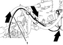
-
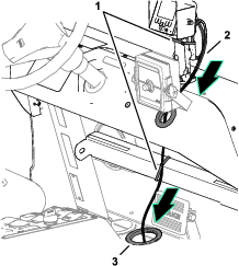
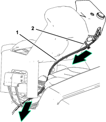
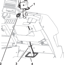
Route the front wire harness of the kit through the grommet in the dash panel and the grommet in the floor of the machine (Figure 45).
-
Secure the harness to the arm of the display/controller and the channel below the dash with cable ties (Figure 45).
Note: Ensure that there is slack in the harness to allow the machine operator to adjust the position of the display/controller.
-
At the bottom of the machine, route the front wire harness through the 3 hose guards (Figure 45).
-
Route the ring terminal and socket terminal connectors through the hole in the crossmember as shown in Figure 45.
-
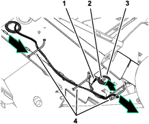
Route the ring terminal and socket terminal connectors toward the fuse block and ground block (Figure 46).
Routing the Front Wire Harness Along the Spray Tank
-
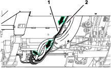
At the right side of the spray tank, route the front wire harness rearward along the wire harness for the sprayer (Figure 47).
-
Route the 12-socket connector for the front wire harness to the front of the center spray section, adjacent to the right section actuator (Figure 47).
-
Secure the front wire harness to the sprayer harness with cable ties.
Routing the Front Wire Harness at the Operator’s Platform
-
Route the front wire harness of the kit attached to the display/controller along the socket arm and under the console for the machine (Figure 48).
-
Secure the harness to the arm with a cable tie.
Note: Ensure that there is slack in the harness to allow the machine operator to adjust the position of the display/controller.
-
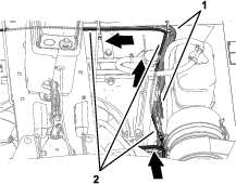
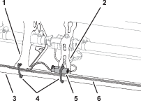
At the shock support tube, route the front wire harness to the left, along the sprayer wire harness of the machine (Figure 49).
-
Route the ring terminal and socket terminal connectors toward the fuse block and ground block (Figure 50).
-
Along the left, upper frame tube, route the front wire harness rearward, along the sprayer wire harness (Figure 51).
Routing the Front Wire Harness Under the Spray Tank
Routing the Front Wire Harness at the Operator’s Platform
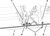
-
Route the front wire harness of the kit along the display/controller arm, and down along the sprayer control support tube (Figure 54).
-
Secure the harness to the arm with a cable tie.
Note: Ensure that there is slack in the harness to allow the machine operator to adjust the position of the display/controller.
-
Route the front wire harness along the wire harness for the sprayer, and secure the harnesses to the support tube with a cable tie (Figure 55).
-
Route the ring terminal and socket terminal connectors toward the fuse block and ground block (Figure 55).
-
At the center console, route the front wire harness along the sprayer wire harness, and align the front wire harness inside the support clamps (Figure 56).
-
Secure the front wire harness and the sprayer wire harness with 2 cable ties.
Routing the Front Wire Harness Along the Spray Tank
-
At the left side or the spray tank, route the front wire harness rearward, along the sprayer wire harness (Figure 57).
-
Route the 12-socket connector for the front wire harness along the front of the center spray section, toward the right boom-lift actuator (Figure 58).
-
Secure the front wire harness to the sprayer harness with cable ties.
Routing the Front Wire Harness at the Operator’s Platform
-
Route the front wire harness downward and across the sprayer control console (Figure 59).
-
Secure the harness to the arm with a cable tie.
Note: Ensure that there is slack in the harness to allow the machine operator to adjust the position of the display/controller.
-
Route the front wire harness rearward, along the sprayer wire harness (Figure 60).
-
Route the ring terminal and socket terminal connectors toward the fuse block and ground block (Figure 61).
-
At the center console, route the front wire harness along the sprayer wire harness, and align the front wire harness inside the support clamps (Figure 62).
-
Secure the front wire harness and the sprayer wire harness with 2 cable ties.
Routing the Front Wire Harness Along the Spray Tank
-
At the right side of the spray tank, route the front wire harness rearward along the wire harness for the sprayer (Figure 63).
-
Align the front wire harness into the clamp supporting the sprayer harness.
-
Rout the front wire harness along the wire harness toward the center spray section (Figure 64).
-
Route the 12-socket connector for the front wire harness toward the boom-lift valve (Figure 65).
-
Secure the front wire harness to the sprayer harness with cable ties.
Routing the Front Wire Harness at the Operator’s Platform
-
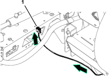
Route the front wire harness through the grommet in the dash panel (Figure 66).
-
Secure the harness to the arm with a cable tie.
Note: Ensure that there is slack in the harness to allow the machine operator to adjust the position of the display/controller.
-
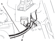
Route the front wire harness along the wire harness for the machine, and through the grommet on the floor (Figure 67).
-
Secure the harnesses to the hydraulic hoses with a cable tie (Figure 67).
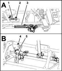
Routing the Front Wire Harness at the Operator’s Platform
-
Remove the forward heat shield and undercarriage shroud; refer to the Operator’s Manual.
-
Route the front wire harness of the kit along the display/controller arm, and over the dash panel (Figure 68).
-
Secure the harness to the arm with a cable tie.
Note: Ensure that there is slack in the harness to allow the machine operator to adjust the position of the display/controller.
-
Route the front wire harness along the wire harness for the machine, and through the grommet on the floor (Figure 69).
Routing the Front Wire Harness at the Operator’s Platform
-
If equipped, remove the forward heat shield and undercarriage shroud; refer to the Operator’s Manual.
-
Route the front wire harness through the grommet in the dash panel (Figure 70).
-
Secure the harness to the arm with a cable tie.
Note: Ensure that there is slack in the harness to allow the machine operator to adjust the position of the display/controller.
-
Route the front wire harness along the wire harness for the machine, and through the grommet on the floor (Figure 70).
-
Secure the harnesses to the hydraulic hoses with a cable tie (Figure 70).
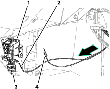
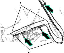
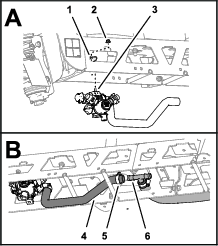
Routing the Front Wire Harness to the Fuse Block and Ground Block
-
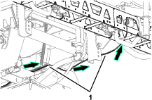
Secure the harnesses to the hydraulic hoses with a cable tie (Figure 71).
-
At the engine compartment, route the branch of the front wire harness with the socket terminal and ring terminal connectors up, and long the machine wire harness (Figure 72).
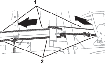
-
Route the front harness under the center console, and rearward toward the fuse block and ground block (Figure 73).
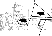
Routing the Front Wire Harness Under the Spray Tank
-
At the right frame channel, route the front wire harness along the wire harness of the machine (Figure 74).
-
Secure the front wire harness to the machine wire harness with cable ties.
-
Route the front wire harness to the center spray section (Figure 75 and Figure 76).
-
If equipped, install the forward heat shield and undercarriage shroud; refer to the Operator’s Manual.
Connecting Harness to the Fuse and Ground Blocks
-
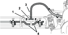
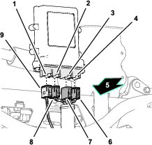
Plug the blade connector of the fuse block labeled OPTIONS POWER into the socket terminal connector of the front wire harness of the kit (Figure 77).
-
Remove the terminal screw from the ground block (Figure 78).
-
Secure the ring terminal of the front wire harness to the ground block with the terminal screw (Figure 78).
-
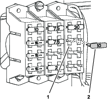
Insert the fuse (10 A) into the fuse socket for the options power circuit (Figure 79).
Removing the Spray Nozzles
Disconnecting the Section-Supply Hoses
-
At the outboard spray section, remove the 2 hose clamps that secures the nozzle hoses to the barbed T-fitting, and remove the fitting from the hoses as shown in Figure 80.
-
Repeat step 1 at the other outboard spray section.
-
At the front side of the center spray section, remove the 2 hose clamps that secures the nozzle hoses to the barbed T-fitting, and remove the fitting from the hoses as shown in Figure 81.
Removing the Nozzle Caps
Removing the Spray-Nozzle Turrets
-
Cut the sprayer hoses of the outer and center spray sections as shown in Figure 83 and Figure 84.
-
Remove the locknuts that secure the 11 or 12 spray-nozzle turret to the outer and center spray sections, and remove the nozzle turrets and hoses from the machine (Figure 85).
Note: Retain the locknuts for installation in Assembling the Flowmeters and Spray-Nozzle Turrets to the Spray Sections.
Removing the Barbed Fitting and Hoses from the Spray-Nozzle Turrets
-
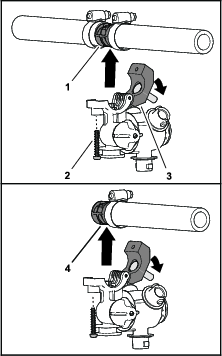
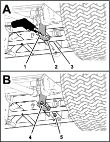
Remove the screw that secures the saddle of the spray-nozzle turret, and open the saddle (Figure 86).
Note: Keep the bolt and saddle together.
-
Remove the double or single barbed fitting, and attached hose(s) as show in Figure 86.
Note: You no longer need the barbed fitting and attached hose(s).
-
Repeat steps 1 and 2 for the other spray-nozzle turrets.
Retain the spray-nozzle turrets and bolts for installation in Assembling the Flowmeters and Spray-Nozzle Turrets to the Spray Sections. You no longer need the barbed fittings and hoses.
Assembling the Nozzle Flowmeters and Spray-Nozzle Turrets
Parts needed for this procedure:
| Flow meter—11 or 12 spray nozzle machines | 11 |
| Flow meter—12 spray nozzle machines | 1 |
| Quick-disconnect cap and retainer—11 or 12 spray nozzle machines | 6 |
| Straight barbed quick-disconnect fitting and retainer—11 or 12 spray nozzle machines | 14 |
| Straight barbed quick-disconnect fitting and retainer—12 spray nozzle machines | 2 |
| 90° barbed quick-disconnect fitting—11 or 12 spray nozzle machines | 2 |
| Hose clamp—11 or 12 spray nozzle machines | 13 |
| Hose clamp—12 spray nozzle machines | 3 |
| Hose (38 cm or 15 inches)—11 or 12 spray nozzle machines | 4 |
| Hose (20 cm or 8 inches)—12 spray nozzle machines | 2 |
| Hose (17 cm or 6-1/2 inches)—11 or 12 spray nozzle machines | 4 |
| Formed hose—11 or 12 spray nozzle machines | 2 |
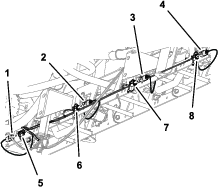
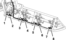
Location of the Flowmeter and Spray-Nozzle Turret Positions
Assembling the Flowmeters and Spray-Nozzle Turrets L1 and L2
Important: Lubricate the O-rings with the silicon grease provided with this kit before assembling the quick-disconnect fittings.
-
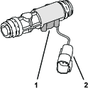
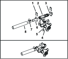
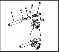
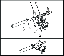
Assemble the straight barbed quick-disconnect fitting and a hose (38 cm or 15 inches) with a hose clamp as shown in Figure 89.
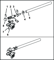
-
Assemble the quick-disconnect cap and straight barbed quick-disconnect fitting to the flow meter with 2 retainers as shown in Figure 89.
Note: Align the flowmeter sensor right.
-
Assemble the flow meter to a spray-nozzle turret with the screw that you removed in Removing the Barbed Fitting and Hoses from the Spray-Nozzle Turrets in as shown in Figure 89.
Important: Ensure that the O-ring is assembled onto the transfer tube. Carefully align the 10 mm (3/8 inch) port in the flowmeter body with the transfer tube of the turret body.
-
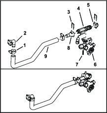
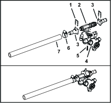
Assemble a straight barbed quick-disconnect fitting to a hose (38 cm or 15 inches) with a hose clamp as shown in Figure 90.
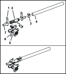
-
Assemble the 2 straight barbed quick-disconnect fitting to the flow meter with 2 retainers as shown in Figure 90.
Note: Align the flowmeter sensor right.
-
Assemble the flow meter to a spray-nozzle turret with the screw that you removed in Removing the Barbed Fitting and Hoses from the Spray-Nozzle Turrets as shown in Figure 90.
Important: Ensure that the O-ring is assembled onto the transfer tube. Carefully align the 10 mm (3/8 inch) port in the flowmeter body with the transfer tube of the turret body.
-
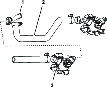
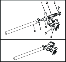
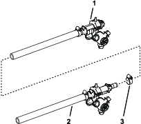
Assemble the flowmeter and nozzle turrets L1 and L2 with a hose clamp as shown in Figure 91.
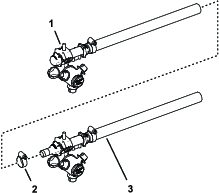
-
Use a piece of tape to mark flowmeter and nozzle turret assembly L1 AND L2.
Assembling the Flowmeters and Spray-Nozzle Turrets L3 and L4
Important: Lubricate the O-rings with the silicon grease provided with this kit before assembling the quick-disconnect fittings.
-
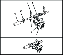
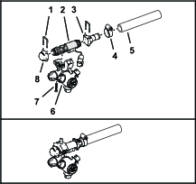
Assemble a straight barbed quick-disconnect fitting to a hose (17 cm or 6-1/2 inches) with a hose clamp as shown in Figure 92.
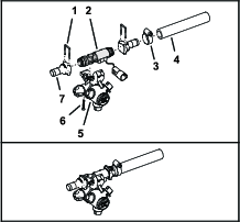
-
Assemble the 2 straight barbed quick-disconnect fitting to the flow meter with 2 retainers as shown in Figure 92.
Note: Align the flowmeter sensor right.
-
Assemble the flow meter to a spray-nozzle turret with the screw that you removed in Removing the Barbed Fitting and Hoses from the Spray-Nozzle Turrets as shown in Figure 92.
Important: Ensure that the O-ring is assembled onto the transfer tube. Carefully align the 10 mm (3/8 inch) port in the flowmeter body with the transfer tube of the turret body.
-
Use a piece of tape to mark flowmeter and nozzle turret assembly L3.
-
Assemble a straight barbed quick-disconnect fitting to a hose (17 cm or 6-1/2 inches) with a hose clamp as shown in Figure 93.
-
Assemble the quick-disconnect cap and straight barbed quick-disconnect fitting to the flow meter with 2 retainers as shown in Figure 93.
Note: Align the flowmeter sensor left.
-
Assemble the flow meter to a spray-nozzle turret with the screw that you removed in Removing the Barbed Fitting and Hoses from the Spray-Nozzle Turrets as shown in Figure 93.
Important: Ensure that the O-ring is assembled onto the transfer tube. Carefully align the 10 mm (3/8 inch) port in the flowmeter body with the transfer tube of the turret body.
-
Use a piece of tape to mark the flowmeter and nozzle turret assembly L4.
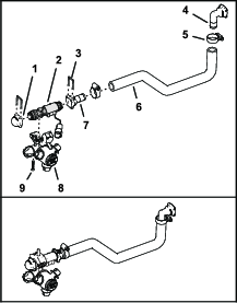
Assembling the Flowmeter and Spray-Nozzle Turret C1
Important: Lubricate the O-rings with the silicon grease provided with this kit before assembling the quick-disconnect fittings.
-
Assemble a 90° barbed quick-disconnect fitting to a formed hose with a hose clamp as shown in Figure 94.
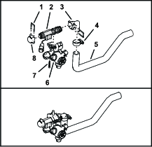
-
Assemble the quick-disconnect cap and 90° barbed quick-disconnect fitting to the flow meter with 2 retainers as shown in Figure 94.
Note: Align the flowmeter sensor left.
-
Assemble the flow meter to a spray-nozzle turret with the screw that you removed in Removing the Barbed Fitting and Hoses from the Spray-Nozzle Turrets as shown in Figure 94.
Important: Ensure that the O-ring is assembled onto the transfer tube. Carefully align the 10 mm (3/8 inch) port in the flowmeter body with the transfer tube of the turret body
-
Use a piece of tape to mark the flowmeter and nozzle turret assembly C1
Assembling the Flowmeters and Spray-Nozzle Turrets C2 and C3
Important: Lubricate the O-rings with the silicon grease provided with this kit before assembling the quick-disconnect fittings.
-
Assemble a straight barbed quick-disconnect fitting to a hose (76 mm or 3 inches) with a hose clamp as shown in Figure 95.
-
Assemble the 2 straight barbed quick-disconnect fitting to the flow meter with 2 retainers as shown in Figure 148.
Note: Align the flowmeter sensor right.
-
Assemble the flow meter to a spray-nozzle turret with the screw that you removed in Removing the Barbed Fitting and Hoses from the Spray-Nozzle Turrets as shown in Figure 95.
Important: Ensure that the O-ring is assembled onto the transfer tube. Carefully align the 10 mm (3/8 inch) port in the flowmeter body with the transfer tube of the turret body.
-
Assemble a 90° barbed quick-disconnect fitting to a formed hose with a hose clamp (Figure 96).
-
Assemble the quick-disconnect cap and 90° barbed quick-disconnect fitting to the flow meter with 2 retainers as shown in Figure 96.
Note: Align the flowmeter sensor left.
-
Assemble the flow meter to a spray-nozzle turret with the screw that you removed in Removing the Barbed Fitting and Hoses from the Spray-Nozzle Turrets as shown in Figure 96.
Important: Ensure that the O-ring is assembled onto the transfer tube. Carefully align the 10 mm (3/8 inch) port in the flowmeter body with the transfer tube of the turret body.
-
Assemble the flowmeter and nozzle turrets C2 and C3 with a hose clamp as shown in Figure 97.
-
Use a piece of tape to mark the flowmeter and nozzle turret assembly C2 AND C3.
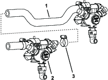
Assembling the Flowmeter and Spray-Nozzle Turret C1 and C2
Important: Lubricate the O-rings with the silicon grease provided with this kit before assembling the quick-disconnect fittings.
-
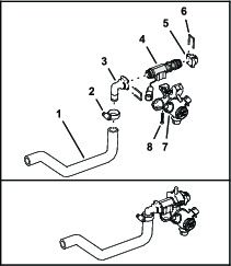
Assemble a 90° barbed quick-disconnect fitting and a straight barbed fitting to the formed hose with 2 hose clamps (Figure 98).
-
Assemble the quick-disconnect cap and the straight barbed quick-disconnect fitting to the flow meter with 2 retainers as shown in Figure 98.
Note: Align the flowmeter sensor right.
-
Assemble the flow meter to a spray-nozzle turret with the screw that you removed in Removing the Barbed Fitting and Hoses from the Spray-Nozzle Turrets as shown in Figure 98.
Important: Ensure that the O-ring is assembled onto the transfer tube. Carefully align the 10 mm (3/8 inch) port in the flowmeter body with the transfer tube of the turret body
-
Assemble a straight barbed quick-disconnect fitting to a hose 20 cm (8 inch) with a hose clamp as shown in Figure 99.
-
Assemble the straight barbed quick-disconnect fitting to the flow meter with a retainers as shown in Figure 99.
Note: Align the flowmeter sensor left.
-
Assemble the flow meter to a spray-nozzle turret with the screw that you removed in Removing the Barbed Fitting and Hoses from the Spray-Nozzle Turrets as shown in Figure 99.
Important: Ensure that the O-ring is assembled onto the transfer tube. Carefully align the 10 mm (3/8 inch) port in the flowmeter body with the transfer tube of the turret body
-
Assemble the flowmeter and nozzle turrets C1 and C2 with retainer for the quick-disconnect fitting as shown in Figure 100.
-
Use a piece of tape to mark the flowmeter and nozzle turret assembly C1 AND C2.
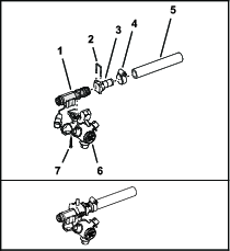
Assembling the Flowmeters and Spray-Nozzle Turrets C3 and C4
Important: Lubricate the O-rings with the silicon grease provided with this kit before assembling the quick-disconnect fittings.
-
Assemble a straight barbed quick-disconnect fitting to a hose (20 cm or 8 inches) with a hose clamp as shown in Figure 101.
-
Assemble the straight barbed quick-disconnect fitting to the flow meter with a retainers as shown in Figure 101.
-
Assemble the flow meter to a spray-nozzle turret with the screw that you removed in Removing the Barbed Fitting and Hoses from the Spray-Nozzle Turrets as shown in Figure 101.
Important: Ensure that the O-ring is assembled onto the transfer tube. Carefully align the 10 mm (3/8 inch) port in the flowmeter body with the transfer tube of the turret body.
-
Assemble a 90° barbed quick-disconnect fitting and a straight barbed fitting to the formed hose with 2 hose clamps (Figure 102).
-
Assemble the quick-disconnect cap and the straight barbed quick-disconnect fitting to the flow meter with 2 retainers as shown in Figure 102.
Note: Align the flowmeter sensor left.
-
Assemble the flow meter to a spray-nozzle turret with the screw that you removed in Removing the Barbed Fitting and Hoses from the Spray-Nozzle Turrets as shown in Figure 102.
Important: Ensure that the O-ring is assembled onto the transfer tube. Carefully align the 10 mm (3/8 inch) port in the flowmeter body with the transfer tube of the turret body.
-
Assemble the flowmeter and nozzle turrets C3 and C4 with retainer for the quick-disconnect fitting as shown in Figure 103.
-
Use a piece of tape to mark the flowmeter and nozzle turret assembly C3 AND C4.
Assembling the Flowmeters and Spray-Nozzle Turrets R1 and R2
Important: Lubricate the O-rings with the silicon grease provided with this kit before assembling the quick-disconnect fittings.
-
Assemble a straight barbed quick-disconnect fitting to a hose (17 cm or 6-1/2 inches) with a hose clamp as shown in Figure 104).
-
Assemble the quick-disconnect cap and straight barbed quick-disconnect fitting to the flow meter with 2 retainers as shown in Figure 104.
Note: Align the flowmeter sensor right.
-
Assemble the flow meter to a spray-nozzle turret with the screw that you removed in Removing the Barbed Fitting and Hoses from the Spray-Nozzle Turrets as shown in Figure 104.
Important: Ensure that the O-ring is assembled onto the transfer tube. Carefully align the 10 mm (3/8 inch) port in the flowmeter body with the transfer tube of the turret body
-
Use a piece of tape to mark the flowmeter and nozzle turret assembly R1.
-
Assemble a straight barbed quick-disconnect fitting to a hose (17 cm or 6-1/2 inches) with a hose clamp as shown in Figure 105.
-
Assemble the 2 straight barbed quick-disconnect fitting to the flow meter with 2 retainers as shown in Figure 105.
Note: Align the flowmeter sensor left.
-
Assemble the flow meter to a spray-nozzle turret with the screw that you removed in Removing the Barbed Fitting and Hoses from the Spray-Nozzle Turrets as shown in Figure 104.
Important: Ensure that the O-ring is assembled onto the transfer tube. Carefully align the 10 mm (3/8 inch) port in the flowmeter body with the transfer tube of the turret body
-
Use a piece of tape to mark the flowmeter and nozzle turret assembly R2.
Assembling the Flowmeters and Spray-Nozzle Turrets R3 and R4
Important: Lubricate the O-rings with the silicon grease provided with this kit before assembling the quick-disconnect fittings.
-
Assemble a straight barbed quick-disconnect fitting to a hose (38 cm or 15 inches) with a hose clamp as shown in Figure 106.
-
Assemble the 2 straight barbed quick-disconnect fitting to the flow meter with 2 retainers as shown in Figure 106.
Note: Align the flowmeter sensor right.
-
Assemble the flow meter to a spray-nozzle turret with the screw that you removed in Removing the Barbed Fitting and Hoses from the Spray-Nozzle Turrets as shown in Figure 106.
Important: Ensure that the O-ring is assembled onto the transfer tube. Carefully align the 10 mm (3/8 inch) port in the flowmeter body with the transfer tube of the turret body.
-
Assemble a straight barbed quick-disconnect fitting to a hose (38 cm or 15 inches) with a hose clamp as shown in Figure 107.
-
Assemble the quick-disconnect cap and straight barbed quick-disconnect fitting to the flow meter with 2 retainers as shown in Figure 107.
Note: Align the flowmeter sensor left.
-
Assemble the flow meter to a spray-nozzle turret with the screw that you removed in Removing the Barbed Fitting and Hoses from the Spray-Nozzle Turrets as shown in Figure 107.
Important: Ensure that the O-ring is assembled onto the transfer tube. Carefully align the 10 mm (3/8 inch) port in the flowmeter body with the transfer tube of the turret body.
-
Assemble the flowmeter and nozzle turrets R3 and R4 with a hose clamp as shown in Figure 108.
-
Use a piece of tape to mark flowmeter and nozzle turret assembly 10 and 11.
Assembling the Flowmeters and Spray-Nozzle Turrets to the Spray Sections
Parts needed for this procedure:
| Hose clamp | 6 |
Installing Flowmeters and Spray-Nozzle Turrets L1 and L2
-
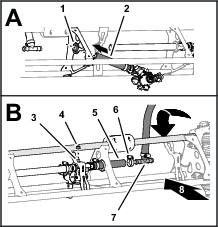
At the outboard end of the left spray section, assemble the hose of flowmeter/nozzle turrets L1 and L2 through the outboard truss grommet (Figure 109).
-
Align the turret saddle bolts through the holes in the nozzle supports, and secure the flowmeter/nozzle turret assemblies to the supports (Figure 109) with 2 flange locknuts (5/16 inch).
Installing Flowmeters and Spray-Nozzle Turrets L3
-
Assemble the flowmeter/nozzle turret L3 through the inboard truss grommet (Figure 110).
-
Assemble the hose at the inboard side of nozzle/flowmeter assembly L2 onto the straight barbed fitting nozzle/flowmeter assembly L3, and secure the hose to the fitting with a hose clamp (Figure 110).
-
Assemble the barbed T-fitting for the left section-supply hose into the short hose of flowmeter/nozzle turret L3 with a hose clamp (Figure 110).
-
Align the turret saddle bolt through the holes in the nozzle support, and secure the flowmeter/nozzle turret assembly to the support (Figure 110) with a flange locknuts (5/16 inch).
Installing Flowmeters and Spray-Nozzle Turrets L4
-
Assemble the hose of flowmeter/nozzle turret L4 to the barbed T-fitting for the left section-supply hose with a hose clamp (Figure 111).
-
Align the turret saddle bolt through the holes in the nozzle support, and secure the flowmeter/nozzle turret assembly to the support (Figure 111) with a flange locknuts (5/16 inch).
Installing the Flowmeter and Spray-Nozzle Turret C1
-
At the left end of the center spray section, assemble the flowmeter/nozzle turret C1 to the truss as shown in Figure 112.
-
Align the turret saddle bolt through the holes in the nozzle support, and secure the flowmeter/nozzle turret assembly to the support (Figure 112) with a flange locknuts (5/16 inch).
-
Assemble the barbed T-fitting for the center section-supply hose into the formed hose of flowmeter/nozzle turret C1 with a hose clamp (Figure 112).
Installing the Flowmeters and Spray-Nozzle Turrets C2 and C3
-
Align the nozzle/flowmeter assembly that you marked flowmeter/nozzle turret C2 and C3 to the center spray section as shown in Figure 113.
-
Assemble the barbed T-fitting for the center section-supply hose into short hose at the inboard end of flowmeter/nozzle turret C2 with a hose clamp (Figure 113).
-
Align the turret saddle bolts through the holes in the nozzle supports, and secure the nozzle/flowmeter assemblies to the supports (Figure 113) with 2 flange locknuts (5/16 inch).
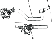
Installing the Flowmeters and Spray-Nozzle Turrets C1 and C2
-
At the center spray section, assemble the flowmeter/nozzle turrets C1 and C2 between the tube stiffeners of the truss (Figure 114).
-
Align the turret saddle bolts through the holes in the nozzle supports, and secure the nozzle/flowmeter assemblies to the supports (Figure 114) with 2 flange locknuts (5/16 inch).
-
Assemble the barbed T-fitting for the center section-supply hose into the formed hose of flowmeter/nozzle turret C2 with a hose clamp (Figure 112).
Installing the Flowmeters and Spray-Nozzle Turrets C3 and C4
-
Assemble the flowmeter/nozzle turrets C3 and C4 between the tube stiffeners of the truss (Figure 115).
-
Align the turret saddle bolts through the holes in the nozzle supports, and secure the nozzle/flowmeter assemblies to the supports (Figure 115) with 2 flange locknuts (5/16 inch).
-
Assemble the barbed T-fitting for the center section-supply hose into the short hose of flowmeter/nozzle turrets C3 with a hose clamp (Figure 115).
Installing Flowmeters and Spray-Nozzle Turrets R3 and R4
-
At the outboard end of the right spray section, assemble the nozzle/flowmeter positions 10 and 11 through the outboard grommet of the truss (Figure 116).

-
Align the turret saddle bolts through the holes in the nozzle supports, and secure the nozzle/flowmeter assemblies to the supports (Figure 116) with 2 flange locknuts (5/16 inch).
Installing the Flowmeter and Spray-Nozzle Turret R2
-
Assemble the hose of flowmeter/nozzle turret R2 through the inboard truss grommet (Figure 117).
-
Assemble the hose at the inboard side of flowmeter/nozzle turret R3 onto the straight barbed fitting of flowmeter/nozzle turret R2, and secure the hose to the fitting with a hose clamp (Figure 117).
-
Align the barbed T-fitting for the right section-supply hose to the behind the top truss tube of the right-boom section as shown in Figure 117.
-
Assemble the barbed T-fitting for the right section-supply hose into the short hose of flowmeter/nozzle turret R2 with a hose clamp (Figure 117).
-
Align the turret saddle bolt through the holes in the nozzle support, and secure the nozzle/flowmeter assembly to the support (Figure 117) with a flange locknuts (5/16 inch).
Installing the Flowmeter and Spray-Nozzle Turret R1
-
Assemble the hose of flowmeter/nozzle turret R1 to the barbed T-fitting for the right section-supply hose with a hose clamp (Figure 118).
-
Align the turret saddle bolt through the holes in the nozzle support, and secure the nozzle/flowmeter assembly to the support (Figure 118) with a flange locknuts (5/16 inch).
Assembling the Rear Wire Harnesses to the Machine
Parts needed for this procedure:
| Rear wire harness—left (L1, L2, L3, and L4) | 1 |
| Rear wire harness—center (C1, C2, C3, and C4) | 1 |
| Rear wire harness—right (R1, R2, R3, and R4) | 1 |
| Cable tie | 21 |
Aligning the Rear Wire Harnesses to the Machine
-
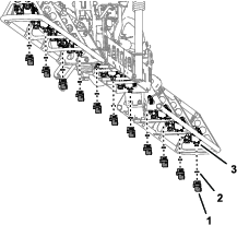
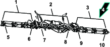
Align the left, center, and right rear wire harnesses to the left, center, and right spray sections as shown in Figure 119.
-
Ensure that the 12-socket connectors of the left, center, and right rear wire harnesses are aligned at the front of the center section, to the right of the boom-lift valve (Figure 120).
Assembling the Rear Wire Harness to the Center Spray Section
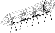
-
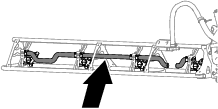
Route the rear wire harness labeled CENTER along the bottom, front of the center section truss (Figure 121 or Figure 122).
-
Insert the rear wire harness connector C1 into the flowmeter C1 connector (Figure 121 or Figure 122, and Figure 123)
-
Insert the rear wire harness connector C2 into the flowmeter C2 connector (Figure 121 or Figure 122, and Figure 123).
-
Insert the rear wire harness connector C3 into the flowmeter C3 connector (Figure 121 or Figure 122, and Figure 123).
-
For 12-spray nozzle machines, remove the cap from rear wire harness connector C4 and insert it into the flowmeter C4 connector (Figure 122, and Figure 123).
-
Secure the rear wire harness to the truss of the center spray section with 7 cable ties.
Assembling the Rear Wire Harness to the Left Spray Section
-
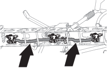
Route the rear wire harness labeled LEFT through the R-clamp, along the section hose, and outward along the bottom, front of the left section truss (Figure 124 and Figure 125).
-
Insert the rear wire harness connector L1 into the flowmeter L1 connector (Figure 125 and Figure 126).
-
Insert the rear wire harness connector L2 into the flowmeter L2 connector (Figure 125 and Figure 126).
-
Insert the rear wire harness connector L3 into the flowmeter L3 connector (Figure 125 and Figure 126).
-
Insert the rear wire harness connector L4 into the flowmeter L4 connector (Figure 125 and Figure 126).
-
Starting at wire harness connector L1, secure the rear wire harness to the 3 tube brackets and 4 nozzle supports of the spray section truss with 7 cable ties as shown in Figure 127.
Important: Ensure that the electrical connectors for the flow meters and rear wire harness secured to the tube brackets and nozzle brackets.
-
Secure the rear wire harness to the section supply hose with cable ties (Figure 124).
Assembling the Rear Wire Harness to the Right Spray Section
-
Route the rear wire harness labeled RIGHT through the R-clamp, along the section hose, and outward along the bottom, front of the right section truss (Figure 128).
-
Insert the rear wire harness connector R4 into the flowmeter R4 connector (Figure 129 and Figure 130).
-
Insert the rear wire harness connector R3 into the flowmeter R3 connector (Figure 129 and Figure 130).
-
Insert the rear wire harness connector R2 into the flowmeter R2 connector (Figure 129 and Figure 130).
-
Insert the rear wire harness connector R1 into the flowmeter R1 connector (Figure 129 and Figure 130).
-
Starting at wire harness connector R4, secure the rear wire harness to the 3 tube brackets and 4 nozzle supports of the spray section truss with 7 cable ties as shown in Figure 131.
Important: Ensure that the electrical connectors for the flow meters and rear wire harness secured to the tube brackets and nozzle brackets.
-
Secure the rear wire harness to the section supply hose with cable ties (Figure 128).
Installing the ECU Bracket
Parts needed for this procedure:
| ECU bracket | 1 |
| Flange-head capscrew (3/8 x 1 inch) | 3 |
| Flange locknut (3/8 inch) | 3 |
Marking the Center Spray Section
-
At the top of the center spray section, measure 160 mm (6-1/4 inches) from the hole at the middle of the truss and mark it as shown in Figure 133.
-
Align the ECU bracket flush to the truss with the hole in the bracket aligned to the mark (Figure 133) that you made in step 1.
-
Mark the outline of the hole on the truss, remove the bracket, and centerpunch the marks.
Installing the ECU Bracket
-
Drill a hole (6 mm or 3/8 inch) though the top of the truss (Figure 134).
-
Align the hole in the ECU bracket with the hole in the truss and assemble the bracket to the truss (Figure 135) with a flange-head capscrew (3/8 x 1 inch) and flange locknut (3/8 inch).
-
At the bottom of the center spray section, use the ECU bracket as a template and drill a hole (6 mm or 3/8 inch) though the truss (Figure 136).
-
Assemble the bracket to the truss with (Figure 136) a flange-head capscrew (3/8 x 1 inch) and flange locknut (3/8 inch).
-
At the top of the center spray section use the ECU bracket as a template, align the drill bit to the Inboard position of the bracket slot, and drill a hole (6 mm or 3/8 inch) through the truss (Figure 137).
-
Assemble the bracket to the truss with (Figure 138) a flange-head capscrew (3/8 x 1 inch) and flange locknut (3/8 inch).
-
Torque the capscrews and locknuts to 37 to 45 N∙m (27 to 33 ft-lb).
Installing the ECU Bracket
-
Locate the right truss of the center spray section (Figure 139).
-
Align the holes and slot in the ECU bracket with the holes in the right truss (Figure 140).
-
Assemble the ECU bracket to the truss (Figure 140) with 3 flange-head capscrew (3/8 x 1 inch) and 3 flange locknut (3/8 inch).
-
Torque the capscrews and nuts to 37 to 45 N∙m (27 to 33 ft-lb).
Installing the ECU Bracket
-
Locate the right truss of the center spray section (Figure 141).
-
Align the holes and slot in the ECU bracket with the holes in the right truss (Figure 142).
-
Assemble the ECU bracket to the truss (Figure 142) with 3 flange-head capscrew (3/8 x 1 inch) and 3 flange locknut (3/8 inch).
-
Torque the capscrews and nuts to 37 to 45 N∙m (27 to 33 ft-lb).
Installing the ECU
Parts needed for this procedure:
| ECU | 1 |
| Capscrew (stainless steel—1/4 x 1-1/2 inches) | 4 |
| Washer (stainless steel—1/4 inch) | 4 |
| Flange locknut (stainless steel—3/8 inch) | 4 |
-
Plug the 12-socket connector for the front wire harness into the connector A (leftmost) of the ECU (Figure 144).
-
Plug the connector marked LEFT of the rear wire harness into the connector B of the ECU (Figure 144).
-
Plug the connector marked RIGHT of the rear wire harness into the connector C of the ECU (Figure 144).
-
Plug the connector marked CENTER of the rear wire harness into the connector D of the ECU (Figure 144).
-
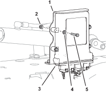
Align the holes in the ECU with the holes in the ECU bracket (Figure 145).
-
Secure the ECU to the bracket (Figure 145) with 4 capscrews (stainless steel—1/4 x 1-1/2 inches), 4 washers (stainless steel—1/4 inch), and 4 flange locknuts (stainless steel—1/4 inch).
Finishing the Kit Installation
-
Connect the battery.
-
If equipped, install the battery-box cover.
-
Insert the key into the ignition switch and rotate the key to the run position.
The splash screen (Figure 146) appears.

Product Overview
Operation
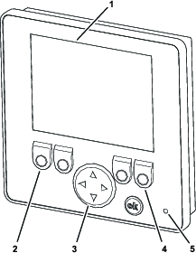
Starting the Display
The display starts when the ignition switch for the machine is in the RUN position.
The status LED illuminates, and the LCD display starts.
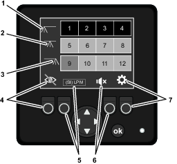
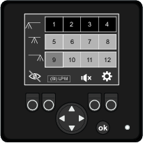
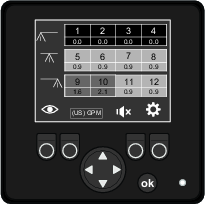
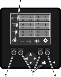
Display Icons
| FUNCTION KEY 1 | FUNCTION KEY 2 | FUNCTION KEY 3 | FUNCTION KEY 4 | ||||
|---|---|---|---|---|---|---|---|
| Switches the flow screen between view flow-rate values or hide flow-rate values | Switches the units values between U.S. GPM or L/MIN | Switches the alarm between ON or SHUT OFF | Switches the display between the settings screen or the flow screen | ||||
| View flow-rate values icon |  | (US) GPM flow-rate units icon |  | Alarm is ON icon |  | Gear icon (always displays on the screen) |  |
| Hide flow-rate values icon |  | (SI) LPM flow-rate units icon |  | Alarm is SHUT OFF icon |  | Press the FUNCTION KEY 4 to go to the settings screen | |
| Default flow-rate values icon = hide | Default flow-rate units = (US) GPM | Default alarm = ON | Press the FUNCTION KEY 4 again to go to the flow screen | ||||
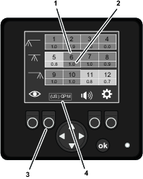
Using the Flow Screen
Note: The NozzAlert system displays the flow-status screen by default.
Flow Indication
-
The flow rate of each nozzle is displayed numerically (Figure 149).
-
Color codes indicate the flow status of each nozzle (Figure 149). Color codes display based on the values programmed in the settings menu.
| Indicator color | Nozzle flow status |
|---|---|
| Black | Nozzle flow error—no flow at the nozzle, or it is shut off |
| Red | Nozzle flow error—out of tolerance greater than 50% |
| Yellow | Nozzle flow error—out of tolerance, but less than 50% |
| Green | Normal—OK |
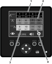
Flow-Status Screen
The flow-status screen displays the nozzle numbers and the flow status color codes that indicate the operating status of each nozzle (Figure 150).
Flow-Rates Screen
The flow-rates screen displays the nozzle numbers and the following information:
-
The flow status color codes indicate the operating status of each nozzle.
-
The measured flow rates of each nozzle.
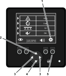
Navigating to the Flow Screens
Note: The NozzAlert system displays the flow-status screen by default.
-
When the display shows a flow screen, you can press function button 1 (Figure 152) to switch between the following screens.
-
Flow-status screen
-
Flow-rates screen
-
-
When the display shows the settings screen, you can press function button 1 to display the flow-status screen or the flow-rates screen.
Note: The system automatically recalls whether you last viewed the flow-status screen or the flow-rates screen.
Units
You can switch the units value between English or international units:
-
(US) GPM (gallons per minute)
-
(SI ) LPM (liters per minute)
-
The default units value is (US) GPM
Setting the Units Value
Press function button 2 to switch between English or international units (Figure 153).
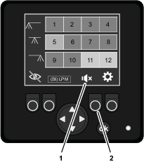
Beeper Enable
You can switch the beeper on or shuts off the beeper.
Enabling or Disabling the Beeper
Press function button 3 to switch between enabling or disabling the beeper (Figure 154).
Using the Settings Menu
Navigating to the Settings Screen
Press the function button 4 to switch to the settings screen.
Error Tolerance
Use the error-tolerance value to set the amount of flow variation among the measured nozzles-flow rates. The error tolerance affects when the yellow (caution) flow status color code displays.
-
A larger error tolerance value allows more difference between nozzles-flow rates.
-
A smaller error tolerance value allows more difference between nozzles-flow rates.
-
The error tolerance range is 5% to 45%.
-
You can change the error-tolerance value in 5% increments.
-
The default error-tolerance value is 15%.
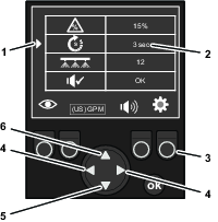
Setting the Error Tolerance Value
-
On the SETTINGS screen, press up or down the navigation/input button until the active-setting indicator aligns with the ERROR TOLERANCE entry (Figure 156).
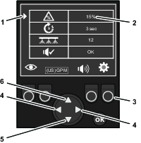
-
Use the left or right change value arrow on the navigation/input button (Figure 156) to change the error-tolerance value (%) as follows:
-
Press the left change value arrow to lower the error tolerance value.
-
Press the right change value arrow to raise the error tolerance value.
-
-
If you are finished changing values in the SETTINGS screen, press the function button 4 under the settings-button indicator to return to the flow status screens (Figure 156).
Error Delay
Use the error-delay value to set the amount time the system measures a nozzles flow rate spraying out of tolerance before the display changes the color-code status.
-
A larger error delay value reduces measurement sensitivity, and the display measurements are less sensitive to flow-rate fluctuation.
-
A small error delay value increases measurement sensitivity, and the display measurements are more sensitive to flow-rate fluctuation.
-
The error delay range is 2 to 10 seconds.
-
You can change the error-delay value in 1 second increments.
-
The default error-delay value is 3 seconds.
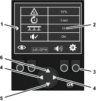
Setting the Error-Delay Value
-
On the SETTINGS screen, press up or down the navigation/input button until the active-setting indicator aligns with the ERROR DELAY entry (Figure 157).
-
Use the left or right change value arrow on the navigation/input button (Figure 157) to change the error-delay value as follows:
-
Press the left change value arrow to lower the delay time.
-
Press the right change value arrow to raise the delay time.
-
-
If you are finished changing values in the SETTINGS screen, press the function button 4 under the settings-button indicator to return to the flow status screens (Figure 157).
System Count
Use the system count value to set the number of flow meters the system measures.
-
You can set the system to measure 11 (flow-meter system) or 12 (flow-meter system).
-
The default display-units value is 12 (flow-meter system).
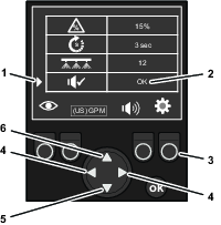
Setting the System Count
-
On the SETTINGS screen, press up or down the navigation/input button until the active-setting indicator aligns with the SYSTEM COUNT entry (Figure 158).
-
Press the left or right change value arrow on the navigation/input button to switch the display-units value between a 11 flow-meter system and a 12 flow-meter system (Figure 158).
-
If you are finished changing values in the SETTINGS screen, press the function button 4 under the settings-button indicator to return to the flow status screens (Figure 158).
Beeper Test
The beeper test allows you to sound the beeper in the display.
Testing the Beeper
-
On the SETTINGS screen, press up or down the navigation/input button until the active-setting indicator aligns with the BEEPER TEST entry (Figure 159).
-
Press the left or right change value arrow on the navigation/input button to sound the beeper (Figure 159).
-
If you are finished changing values in the SETTINGS screen, press the function button 4 under the settings-button indicator to return to the flow status screens (Figure 159).
Troubleshooting
| Problem | Possible Cause | Corrective Action |
|---|---|---|
| The display shows a nozzle with a yellow flow status color code. |
|
|
| The display shows a nozzle with a red flow status color code. |
|
|
| Problem | Possible Cause | Corrective Action |
|---|---|---|
| The display shows a nozzle with a black flow status color code, but the nozzle is spraying. |
|
|