Introduction
The CL-55 modem kit updates the GeoLink® spray system. The GeoLink spray system is an attachment for a turf spray application vehicle and is intended to be used by professional, hired operators in commercial applications. It is designed primarily for spraying on well-maintained lawns in parks, golf courses, sports fields, and on commercial grounds.
Visit www.Toro.com for product safety and operation training materials, accessory information, help finding a dealer, or to register your product.
Installation
Getting a Current Copy of the Software Guide and Quick Start Guide
Purchase through your distributor or download a current copy of the Software Guide and Quick Start Guide from Toro.com.
-
GeoLink GSM systems use Toro Part No. 41634
-
Geolink CDMA systems use Toro Part No. 41633
Important: After the CL-55 Modem Kit is installed, you must use the Software Guide for software version 4.04 and Up and Quick Start Guide for software version 4.04 (or later).
Preparing the Machine
-
Ensure that you completed all active spray jobs.
-
Park the machine on a level surface.
-
Engage the parking brake; refer to the Operator’s Manual.
-
Extend the left and right boom sections to the horizontal position.
-
Shut off the engine; refer to the Operator’s Manual.
-
Remove the key and wait for all moving parts to stop.
Exporting Sprayer Display Inventory Item Data
Changing User Access Level
-
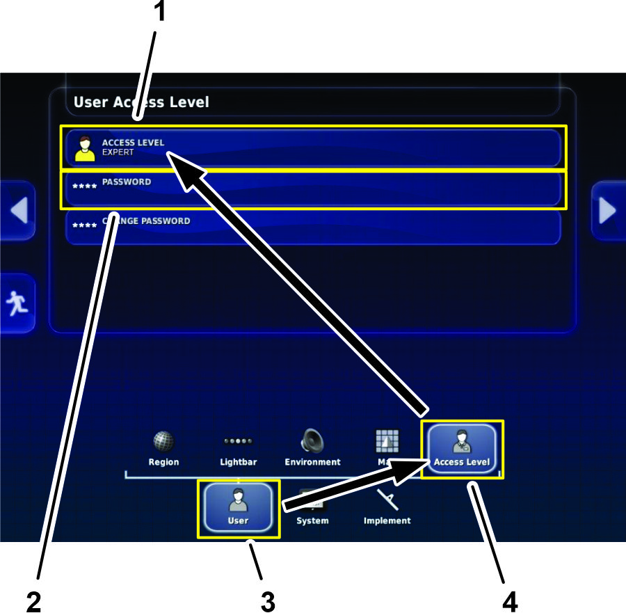
On the home screen, press the SETUP icon.
-
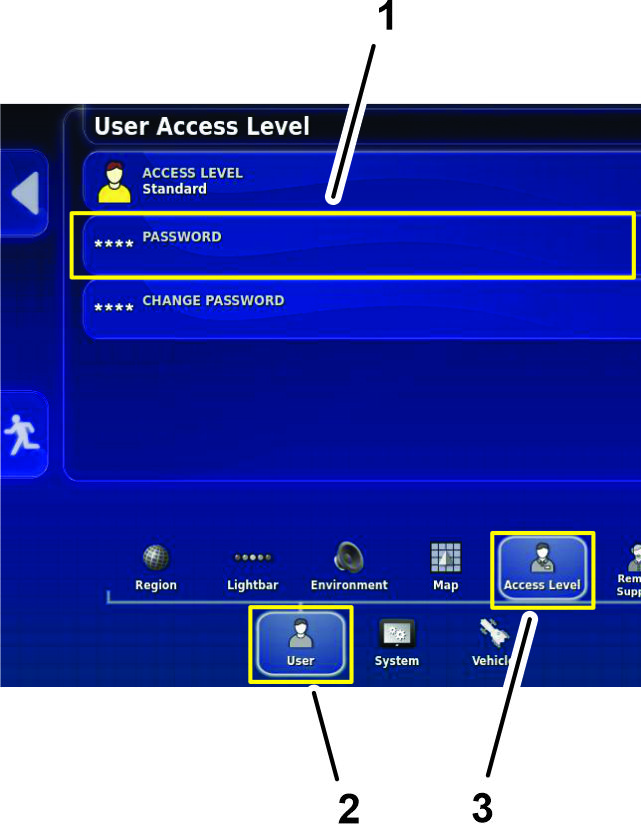
On the setup screen, press the USER icon and the ACCESS LEVEL icon (Figure 1).
-
In the user access level dialog box, press the ACCESS LEVEL icon, and in the drop-down menu, press the EXPERT icon (Figure 1).
-
Press the PASSWORD icon, and type TORO1 in the text box.
Recording N-Trip Settings
Note: Do not use the USB drive from the CL-55 modem kit for saving sprayer display data. Use the USB storage device that you use to backup GeoLink.
-
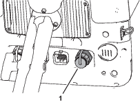
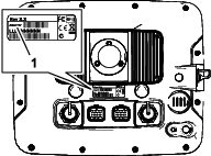
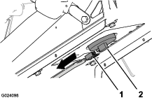
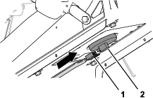
Remove the cap from the USB port of the sprayer-display (Figure 2).
-
Plug the USB storage device that you use to backup GeoLink into the USB port.
-
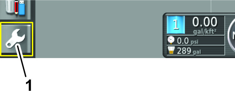
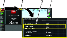
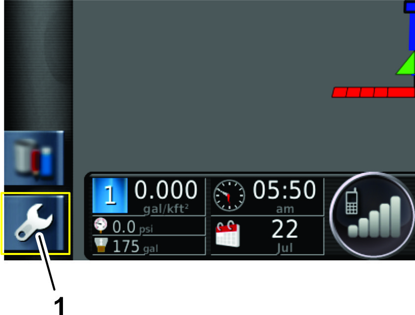
On the home screen, press the SETTINGS icon (Figure 3).
-
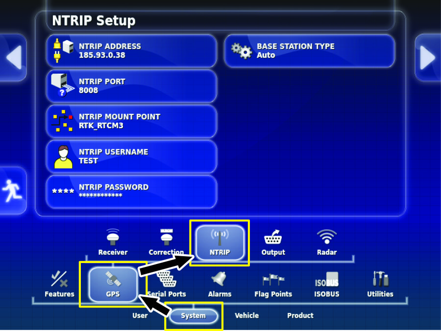
On the System Setup screen, press the SYSTEM icon (Figure 4).
-
Press the GPS icon (Figure 4).
-
Press the NTRIP icon (Figure 4).
-
Press the SCREENSHOT icon to record the current screen image onto the USB storage device.
Exporting Data
-
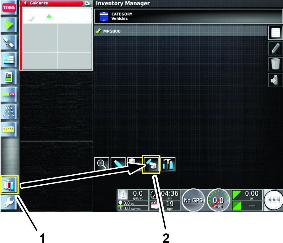
Press the INVENTORY MANAGER icon (Figure 5).
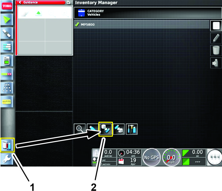
-
At the bottom of the screen, press the EXPORT DATA icon (Figure 5).
-
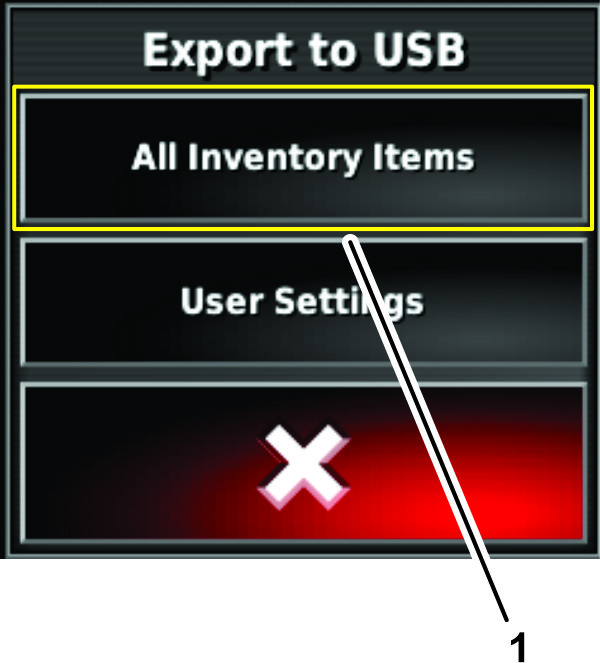
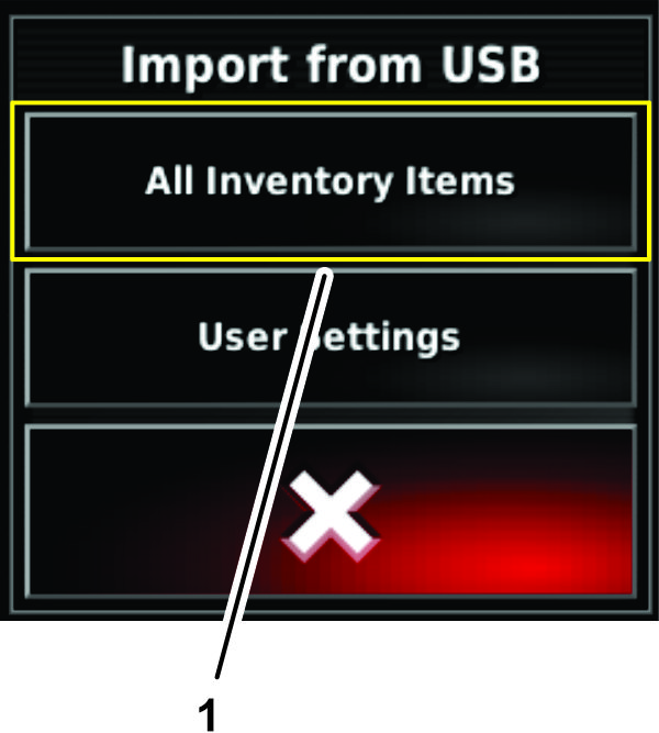
In the Export to USB dialog box, press the ALL INVENTORY ITEMS icon (Figure 6).
-
When the sprayer-display completes the exporting press the return to home page icon, swipe up from the bottom of the screen, and press the EJECT icon at the bottom of the screen.
-
Remove the USB storage device from the USB port.
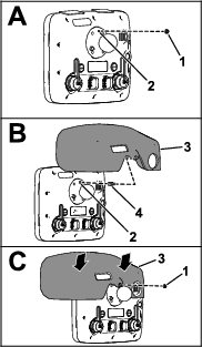
Removing the X30 Sprayer Display
Installing the X25 Monitor Kit (sold separately)
Parts needed for this procedure:
| X25 monitor kit (sold separately—Toro part No. 41637) | 1 |
Applying the Adhesive Strips to the Sprayer Monitor
-
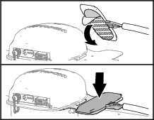
Clean the top surface of the X25 sprayer display with rubbing alcohol and a clean rag.
-
Remove the backing from the 2 adhesive strips.
-
At the top of the sprayer monitor, align the strips to the sprayer monitor as shown in Figure 10.
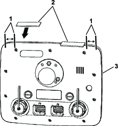
-
Firmly press the adhesive strips to the top of the monitor.
Assembling the Display Hood to the Sprayer Monitor
-
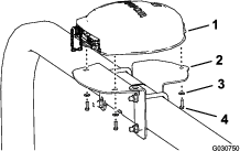
At the back of the sprayer monitor and with the 2 connectors (26 pin) aligned down, remove the top locknut (5 mm) from the stud for the ball-pivot fitting (A of Figure 11).
-
Apply a coat of thread-locking compound (wicking—medium-high strength) to the threads for the nut part of the threaded standoff (Figure 12).
-
Thread the standoff into the stud for the ball-pivot fitting (B of Figure 11) and torque the standoff to 250 N∙cm (22 in-lb).
-
Apply a coat of thread-locking compound (wicking—medium-high strength) to the threads for the stud portion of the threaded standoff (Figure 12).
-
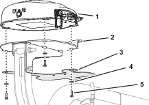
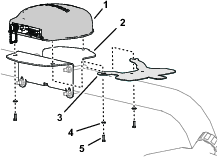
Remove the backing from the 2 adhesive strips that you applied in Applying the Adhesive Strips to the Sprayer Monitor.
-
Align the hole in the display hood with the stud portion of the threaded standoff (B of Figure 11).
-
Assemble the hood to the monitor (C of Figure 11) with the locknut (5 mm) that you removed in step 1.
Note: Press down on the areas of the top of the hood with the adhesive strips underneath.
-
Torque the nut to 250 N∙cm (22 in-lb).
Mounting the Sprayer Monitor to the Dash
-
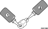
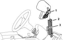
Loosen the knob of the monitor arm until you can slip both the ball pivot for the ball pivot at the back of the sprayer monitor into the socket monitor arm (Figure 13).
-
From the driver’s seat (left seat), adjust to position of the sprayer monitor so that you can easily view the display screen (Figure 13).
-
Tighten the knob for the monitor arm by hand (Figure 13).
-
Align the 26-socket connector of the data harness branch with the 26-pin connector of the sprayer monitor and press the socket connector into the pin connector until the connector latches securely (Figure 14).
Changing User Access Level
-
Rotate the ignition key to the RUN (gasoline) or PREHEAT/RUN (diesel) position.
-
On the home screen, press the SETUP icon.
-
On the setup screen, press the USER icon and the ACCESS LEVEL icon (Figure 15).
-
In the user access level dialog box, press the ACCESS LEVEL icon, and in the drop-down menu, press the EXPERT icon (Figure 15).
-
Press the PASSWORD icon, and type TORO1 in the text box.
Importing Inventory Data
-
Plug the USB storage device that you used in Exporting Sprayer Display Inventory Item Data data into the USB port.
-
Press the INVENTORY MANAGER icon (Figure 16).
-
At the bottom of the screen, press the IMPORT DATA icon (Figure 16).
-
In the import from USB dialog box, press the ALL INVENTORY ITEMS icon (Figure 17).
-
When the sprayer-display completes the exporting, swipe up from the bottom of the screen and press the EJECT icon at the bottom of the screen.
-
Remove the USB storage device from the USB port.
-
Rotate the key switch of the machine to the OFF position, and remove the key.
-
Skip to Disconnecting the Battery.
Verifying the U-Boot Firmware Version
-
Rotate the ignition key to the RUN (gasoline) or PREHEAT/RUN (diesel) position.
-
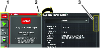
Press the System Information (Toro) icon at the top, left corner of the screen (Figure 18).
-
In the system information mini-view window, press the full-screen icon (Figure 18).
-
In the system information window, look at the U-BOOT VERSION information (Figure 18).
Important: The sprayer monitor must display 1 of the following U-boot versions:• 2013.10-weimx6-1.0.1• 2013.10-weimx6-1.1.0
If the U-boot firmware version is not 2013.10-weimx6-1.0.1 or 2013.10-weimx6-1.1.0, contact the Toro Technical Assistance Center for instructions on updating the firmware.
Updating the GeoLink Software
Parts needed for this procedure:
| USB Drive (GeoLink X25 software version 4.04.40 or higher—CL-55 CDMA Modem Kit) | 1 |
Verifying the Software Version
-
Rotate the ignition key to the RUN (gasoline) or PREHEAT/RUN (diesel) position.
-
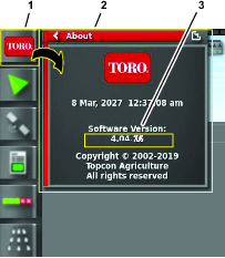
Press the ABOUT (Toro) icon at the upper left corner of the control console (Figure 19).
-
If the software version is 4.04.40 or higher rotate the key switch of the machine to the OFF position, remove the key, and skip to Disconnecting the Battery.
Updating the Sprayer Display Software
-
Ensure that the sprayer display shows the home screen.
-
Plug the USB drive from the CL-55 modem kit into the USB port.
Note: Do not use the USB storage device that you used to export the inventory item data.
-
On the home screen, press the SETUP icon.
-
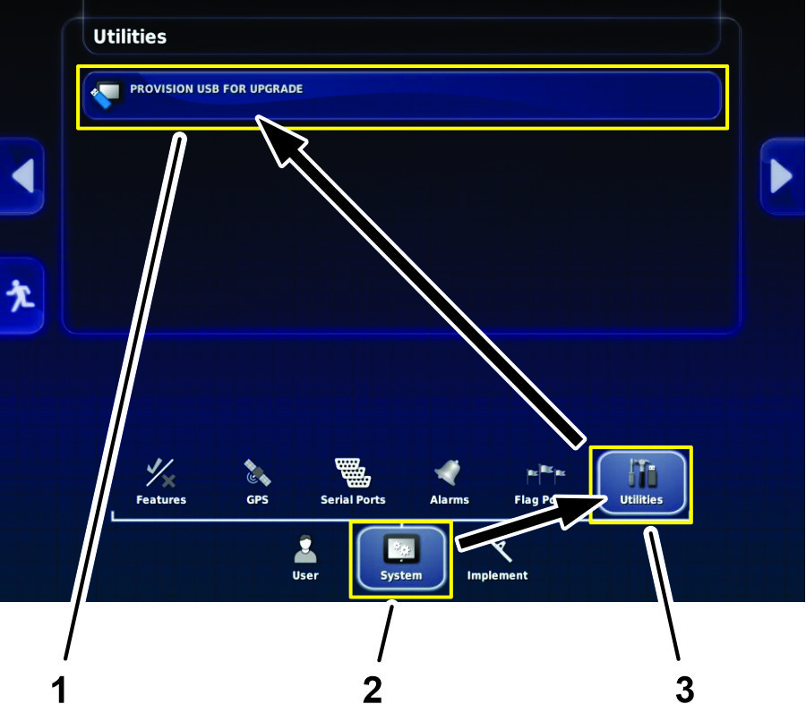
On the setup screen, press the SYSTEM icon and the UTILITIES icon (Figure 20).
-
In the utilities dialog box, press the PROVISION USB FOR UPGRADE icon (Figure 20).
-
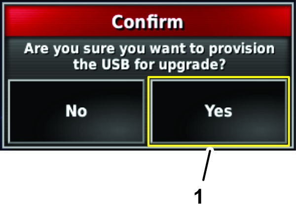
In the confirm dialog box, press the YES icon (Figure 21).
-
When the RESTORE USER DATA message displays, press the YES icon.
Note: The sprayer display retains all previous user data.
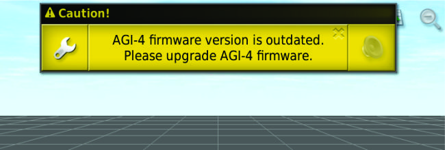
Note: On the home screen, a message displays about upgrading the AGI firmware (Figure 22).
-
Swipe up from the bottom of the screen and press the EJECT icon at the bottom of the screen.
-
Remove the USB drive and install the USB port cap.
Updating the AGI Firmware
-
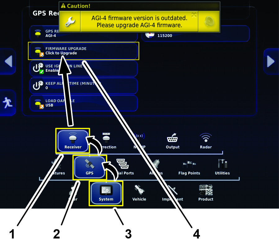
On the setup screen, press the SYSTEM icon and the GPS icon, and the RECEIVER icon (Figure 23).
-
In the GPS receiver dialog box, press the FIRMWARE UPGRADE icon (Figure 23).
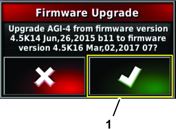
-
In the firmware upgrade dialog box, press the confirm icon (Figure 24).
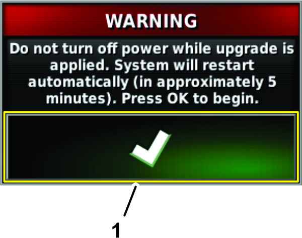
-
In the warning dialog box, press the confirm icon (Figure 25).
Important: Do not turn off machine power while the sprayer display applies the firmware upgrade.
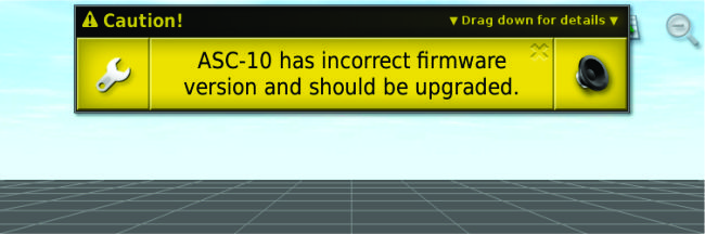
Note: On the home screen, a message displays about upgrading the ASC firmware (Figure 26).
Updating the ASC Firmware
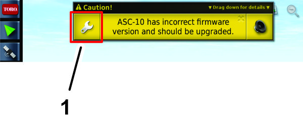
-
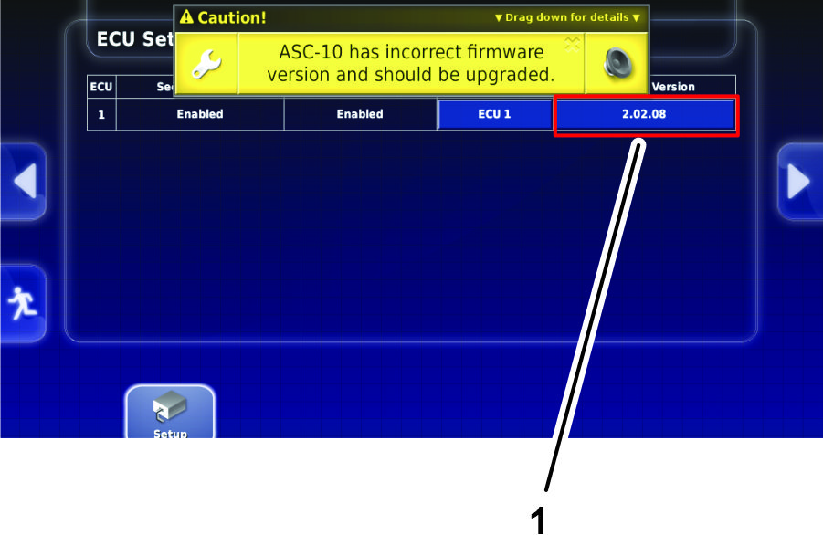
Press the wrench icon in the ASC firmware message to navigate directly to the ECU settings screen in setup (Figure 27).
-
In the Firmware Version column for ECU 1, press the current version (X.XX.XX) icon (Figure 28).
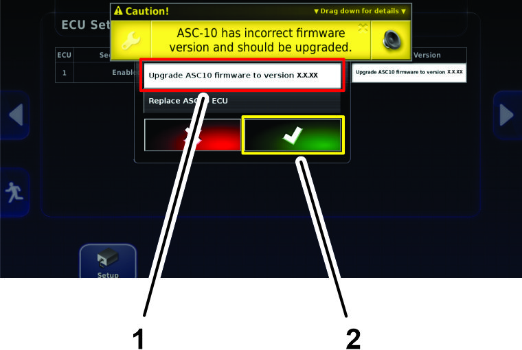
-
In the ASC setting dialog box, press the UPGRADE ASC FIRMWARE TO VERSION 2.02.18 icon, and press the confirm icon (Figure 29).
Note: The options for an ASC firmware upgrade level higher that version 2.02.18 may display.
-
Rotate the key switch of the machine to the OFF position, and remove the key.
Disconnecting the Battery
Disconnecting the Battery Cables
-
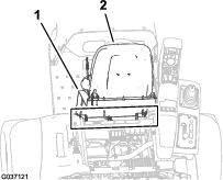
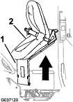
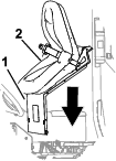
Unlatch the seat by pushing the seat-latch handle rearward (Figure 30).
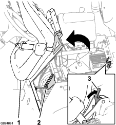
-
Rotate the seat and seat plate forward until the end of the prop rod, at the prop-rod bracket, is at the bottom of the slot in the bracket (Figure 30).
-
Allow the engine to cool completely.
-
Remove the bolt and nut that secures the terminal of the negative-battery cable to the negative post of the battery.
Warning
Incorrect battery cable routing could damage the machine and cables, causing sparks. Sparks can cause the battery gasses to explode, resulting in personal injury.
-
Always disconnect the negative (black) battery cable before disconnecting the positive (red) cable.
-
Always connect the positive (red) battery cable before connecting the negative (black) cable.
Warning
Battery terminals or metal tools could short against metal components, causing sparks. Sparks can cause the battery gasses to explode, resulting in personal injury.
-
When removing or installing the battery, do not allow the battery terminals to touch any metal parts of the machine.
-
Do not allow metal tools to short between the battery terminals and metal parts of the machine.
-
-
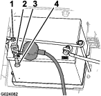
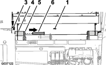
Slide back the insulator cover and remove the bolt and nut that secures the terminal of the positive-battery cable to the positive post of the battery. (Figure 31).
Note: Ensure that the terminals of the battery cables do not touch the battery posts.
Disconnecting the Battery
Warning
Electrical sparks can cause the battery gasses to explode, resulting in personal injury.
Incorrect battery cable routing could damage the sprayer and cables, causing sparks.
-
Always disconnect the negative (black) battery cable before disconnecting the positive (red) cable.
-
Always connect the positive (red) battery cable before connecting the negative (black) cable.
Battery terminals or metal tools could short against metal sprayer components, causing sparks.
-
When removing or installing the battery, do not allow the battery terminals to touch any metal parts of the sprayer.
-
Do not allow metal tools to short between the battery terminals and metal parts of the sprayer.
-
Always keep the battery strap in place to protect and secure the battery.
-
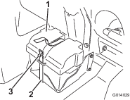
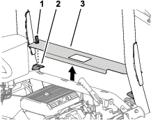
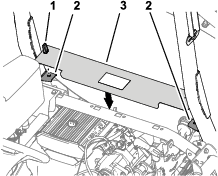
Remove the battery cover (Figure 32).
-
Disconnect the negative (black—ground) cable from the battery post (Figure 33).
-
Disconnect the positive (red) cable from the battery post (Figure 33).
-
Tilt both seats forward and secure them by moving the prop rods into the detents at the end of the slots at the center-console base.
-
Allow the engine to cool completely.
Removing the Seat and the Engine-Access Panel
Removing the Seat
-
Remove the 2-socket connector of the machine wire harness that connects to the seat-switch connector (Figure 34).
-
Remove the hairpin that secures the prop rod to the bracket at the bottom of the seat plate (Figure 35).
-
Remove the 2 hairpins that secure the pivot fitting of the seat plate to the chassis brackets (Figure 36).
-
Remove the 2 pivot pins that secure the seat and seat plate to the chassis (Figure 36).
-
Lift the seat and seat plate up and out of the machine (Figure 37).
Removing the Right Front Fender
Note: If you damage the push-in fasteners removing them, replace the fasteners with Toro Part No. 117-2382.
-
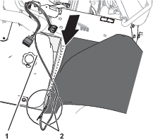
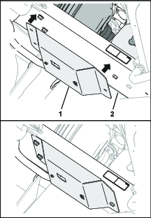
Remove the 2 capscrews (5/16 x 1 inch) and 2 washers (5/16 inch) that secure the bottom console cover and end console cover to the machine, and remove the covers (Figure 39).
-
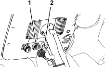
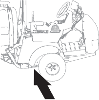
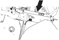
Remove the capscrew (5/16 x 1 inch) and washer (5/16 inch) that secures the right, front fender to the platform floor (Figure 40).
-
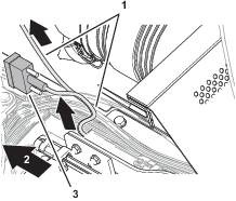
Carefully remove the 2 push-in fasteners that secure the right, front fender to the roll bar mounting channel (Figure 41).
-
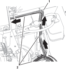
Remove the capscrew (5/16 x 1 inch) and washer (5/16 inch) that secures the right, front fender to the cross-member support (Figure 42).

-
Remove the right, front fender from the machine.
-
Remove the 6 push-in fasteners and 5 washers (9/16 x 1/2 inch) that secure the inner-fender shroud to the right, upper and right, lower-frame tubes (Figure 43).
-
Remove the inner-fender shroud from the machine (Figure 43).
Note: Retain the right, front fender, inner-fender shroud, capscrews, washers, and undamaged push-in fasteners for installation in Installing the Right Front Fender.Replace damaged push-in fasteners with Toro Part No. 117-2382.
Installing the Modem-Antenna Bracket
Parts needed for this procedure:
| Modem antenna bracket. | 1 |
Removing the RTK Bracket
-
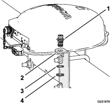
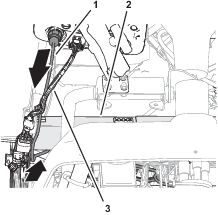
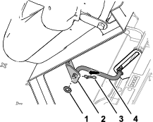
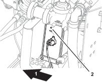
Remove the antenna cable between the coaxial connector of the navigation receiver and the RTK-antenna (Figure 44).
-
Remove the RTK-antenna from the coaxial coupler (Figure 44).
-
Remove the coaxial coupler, lock washer, and jam nut from the bracket (Figure 45 or Figure 46).
Note: Discard the antenna cable, RTK-antenna, coaxial coupler, lock washer, and jam nut.
Removing the RTK-Antenna Bracket
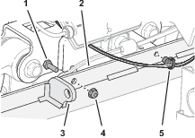
Assembling the Modem-Antenna Bracket to the Receiver Mount
-
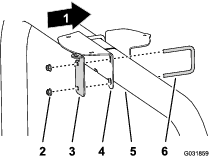
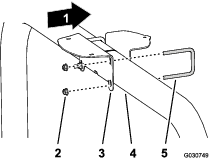
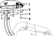
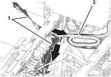
Remove the 3 capscrews (5 x 16 mm) and 3 washers (5 mm) that secure the navigation receiver to the receiver mount (Figure 49 or Figure 50).
-
Align the hole and slot in the modem-antenna bracket with the holes in the receiver mount (Figure 51 or Figure 52).
-
Align the 3 threaded in the base of the navigation receiver to the 3 holes in the receiver mount (Figure 51 or Figure 52).
-
Assemble the navigation receiver and antenna bracket to the mount (Figure 51 or Figure 52) with the 3 capscrews (5 x 16 mm) and 3 washers (5 mm).
-
Torque the 3 bolts to 576 to 712 N∙cm (51 to 63 in-lb).
Installing the Modem Antenna to the Machine
Parts needed for this procedure:
| Modem antenna | 1 |
| Cable ties | 7 |
Installing the Modem Antenna to the Navigation Receiver Mount
-
Clean any grease of oil from the surface of the modem-antenna bracket.
-
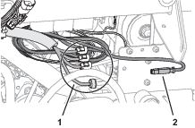
Remove the backing from the double sided adhesive liner at the bottom of the modem antenna (Figure 53).
-
Adhere the modem antenna to the top of the modem-antenna bracket as shown in Figure 53.
-
Secure the antenna bracket with 3 cable ties as shown in Figure 54.
-
Secure the wire harness of the modem antenna to the bracket as shown in Figure 54.
Routing the Modem-Antenna Harness
Routing the Modem-Antenna Harness
Assembling the Modem Data Harness to the Machine
Parts needed for this procedure:
| Modem data harness—300 cm (118 inches) | 1 |
| Cable ties | 8 |
Connecting the Modem Data Harness to the Sprayer Display
-
Align the modem data harness with the RS-232 connector labeled toward the sprayer monitor (Figure 59 or Figure 60).
-
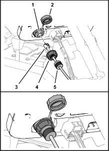
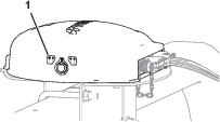
At the front of the sprayer display, remove the cap from the RJ45 port (Figure 61).
-
Plug the RJ45 connector of the modem data cable labeled X-CONSOLE into the RJ45 port of the sprayer display (Figure 61).
-
Assemble the port seal nut over the RJ45 port of the sprayer display, and tighten the seal nut (Figure 61).
-
Assemble compression nut over port seal nut, and tighten the compression nut (Figure 61).
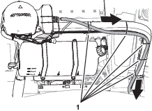
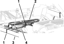
Routing the Modem Data Harness
-
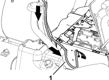
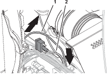
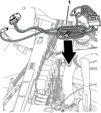
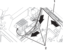
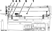
Route the modem data harness along the data harness for the control console (Figure 62).
-
Route the modem data harness under the shock-support tube of the machine (Figure 62).
-
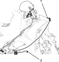
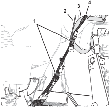
Route the modem data harness across the back if the relays and down (Figure 63).
-
Align the 4-pin connector labeled of the modem data harness near the 4 connectors for the modem-antenna harness as shown in Figure 64.
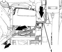
Routing the Modem Data Harness
-
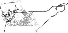
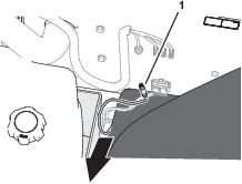
Route the modem data cable through the storage compartment (Figure 65).
-
Route the modem data cable along the wire harness of the machine, and through the grommet in the floor plate (Figure 66).
-
Secure the modem data cable to the machine wire harnesses with 4 cable ties.
-
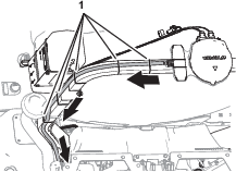
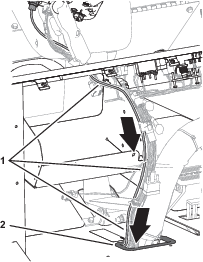
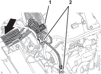
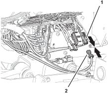
At the bottom of the machine, route the modem data cable rearward, along the wire harness of the machine (Figure 67).

-
At the rear side of the radiator, route the modem data cable upward (Figure 68).

-
Secure the modem data cable to the machine wire harnesses with 4 cable ties.
-
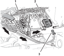
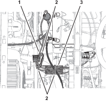
Route the modem data cable along the modem power harness (Figure 69), out the right side of the machine, and between the fuel tank bracket and the right, front fender.
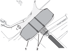
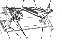
Securing the Navigation-Data and Electrical Harness, Modem-Antenna Harness, and Modem Data Harness
-
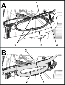
At the right, upper tube frame, bundle the navigation-data and electrical harness, and the CAN 2 ASC 10 BUS wire harness branch to the kit sprayer harness with 2 cable ties (Figure 70).
-
Bundle the modem-antenna harness and secure it to the kit sprayer harness bundle with 2 cable ties (Figure 70).
-
Secure the modem-data harness and the navigation-data and electrical harness to the monitor tube with a cable tie (Figure 71).
-
Secure the modem-data harness to the navigation-data and electrical harness with a cable tie as shown in Figure 71.
Assembling the Modem Power Harness to the Machine
Parts needed for this procedure:
| Modem power harness—1850 mm (72-7/8 inches) | 1 |
| Cable ties | 5 |
Routing the Modem Power Harness
-
Align the modem power harness to the machine as shown in Figure 72.
-
Route the ring terminals of the modem power harness labeled and toward the battery (Figure 73).
-
Route the 4-pin connector labeled and the 18-socket connector labeled of the modem power harness under the fuse block of the machine.
Note: The connector labeled RS232 is not used.
-
At the front of the machine, route the 4-pin connector labeled and the 18-socket connector labeled of the modem power harness to the machine as shown in Figure 74.
Routing the Modem Power Harness
-
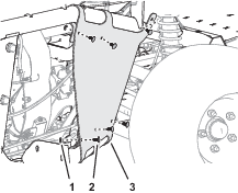
Between the fuel tank bracket and the right, front fender, route the tab terminal (labeled ) and 2 ring terminals (labeled and ) of the modem power harness under the frame of the machine (Figure 75).
-
At the inboard side of the right seat box, route the modem power harness forward and power harness connector labeled RS232 along the machine wire harness (Figure 76).
Note: The connector labeled RS232 is not used.
-
Route the modem power harness across the top of the radiator, along the machine wire harness (Figure 77).
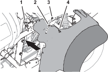
Routing the Harness to the Battery
-
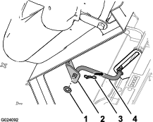
Route the ring terminals of the harness labeled and rearward, and over the seat support (Figure 78).
-
Route the ring terminals under the left frame tube and across the top of the battery (Figure 78).
Note: You will assemble the ring terminals to the battery cables in Assembling the Rear GeoLink Harness, Navigation-Data and Electrical Harness, and Modem Power Harness to the Battery Cables.
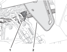
Connecting the Wire Harness to the Fuse Block
-
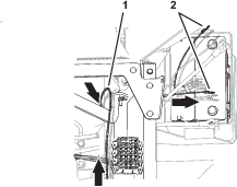
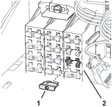
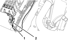
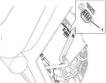
At the front of the machine, plug the terminal of the modem power harness labeled into the socket connector for options power of the fuse block (Figure 79).
Note: If the fuse block of your machine does not have an available options-power circuit, install an additional options-fuse block; refer to your authorized Toro distributor.
-
Near the fuse block bundle the modem power-harness at the 9-pin connector labeled and secure the harness with 2 cable ties as shown in Figure 80.
-
Bundle the modem power-harness at the negative battery cable, and secure the bundle to the battery cable with a cable tie as shown in Figure 80.
-
Insert the fuse (10 A) into the fuse-block socket (Figure 81) for the options power circuit that you used in step 1.
Connecting the Wire Harness to the Fuse Block
-
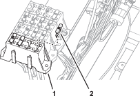
Plug the terminal of the modem power harness labeled into the socket connector for options power of the fuse block (Figure 82).
Note: If the fuse block of your machine does not have an available options-power circuit, install an additional options-fuse block; refer to your authorized Toro distributor.
-
Insert the fuse (10 A) into the fuse-block socket (Figure 83) for the options power circuit that you used in step 1.
-
Secure the switched power and ground branch of the kit wire harness to the machine wire harness with 5 cable ties.
Installing the CL-55 Modem
Parts needed for this procedure:
| CL-55 modem | 1 |
| Modem bracket—Multi Pro 1750 (sold separately—Toro part No. 140-1394) | 1 |
| Modem Mount—Multi Pro 5800 (sold separately—Toro part No. 140-7381) | 1 |
| Capscrew (#10-24 x 1-1/2 inches) | |
| Spacer (1/4 x 3/4 inch) | |
| Locknut (#10-24) | 2 |
Connecting the Antenna Harness to the Modem
Note: You must know if you are installing a CDMA modem or a GSM modem for this procedure.
-
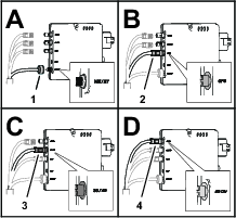
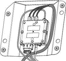
Plug the coaxial connector of the modem-antenna harness labeled into the coaxial port of the CL-55 modem marked WIFI/BT, and tighten the coaxial connector (Figure 84).
-
Plug the blue coaxial push-in connector of the modem-antenna harness labeled into the connector of the CL-55 modem marked , until the connectors latch securely (Figure 84).
-
Plug the violet coaxial push-in connector of the modem-antenna harness labeled into the connector of the CL-55 modem marked , until the connectors latch securely (Figure 84).
-
CDMA Modems Only: Plug the red coaxial push-in connector of the modem-antenna harness labeled into the connector of the CL-55 modem marked , until the connectors latch securely (Figure 84).
Note: The GSM modem does not have an LTE-2 connector.
Connecting the Modem Data and Power Harnesses to the Modem
-
Plug the 4-pin connector of the modem data harness labeled into the 4-socket connector (unmarked) of the CL-55 modem, and tighten the knurled nut of the 4-pin connector (Figure 85).
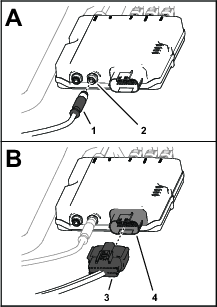
-
Plug the 18-socket connector of the modem power harness labeled into the 18-pin connector of the CL-55 modem (Figure 85).
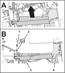
Installing the Modem to the Machine
-
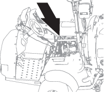
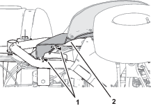
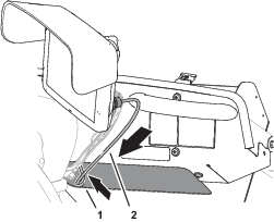
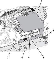
Remove the push-in fastener that secures the wire harness of the machine to the prop-rod bracket (Figure 86).
-
Remove the capscrew (1/4 x 3/4 inch) and flange locknut (1/4 inch) from the flange of the machine frame as shown in Figure 87.
Note: Retain the capscrew and locknut for installing the modem bracket.
-
Remove the push-in fastener that secures the wire harness of the flange of the machine frame (Figure 87).
-
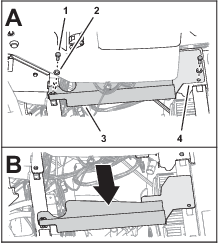
Assemble the modem bracket to the CL-55 modem with 2 slotted machine screws (#10-24 x 1-1/2 inches), 2 spacers (1/4 x 3/4 inch), and 2 locknuts (#10-24) as shown in Figure 88.
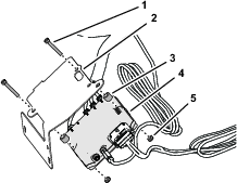
-
Align the modem bracket (Part No. 140-1394) under the prop-rod bracket and behind the flange of the machine frame as shown in Figure 89.
-
Insert the lower push-in fastener of the wire harness into the hole in the modem bracket as shown in Figure 89.
-
Insert the upper push-in fastener of the wire harness into the holes in the modem bracket and prop-rod bracket (Figure 90).
Installing the Modem to the Machine
-
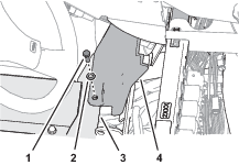
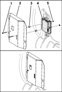
Assemble the modem mount (Part No. 140-7381) to the CL-55 modem with 2 capscrews (#10-24 x 1-1/2 inches), 2 spacers (1/4 x 3/4 inch), and 2 locknuts (#10-24) as shown in Figure 91.
-
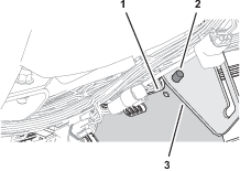
Ensure that the wire harnesses are routed within the modem bracket as shown in Figure 92.
-
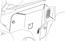
Align the modem bracket to the right seat-box panel (Figure 93).
Align the modem bracket to the right seat-box panel over the bolt heads and secure it with the magnets (Figure 93).
Connecting the Battery
Parts needed for this procedure:
| Battery-clamp bolt (Multi Pro 5800 only; sold separately—Toro part No. 122-9921) | 2 |
Assembling the Rear GeoLink Harness, Navigation-Data and Electrical Harness, and Modem Power Harness to the Battery Cables
-
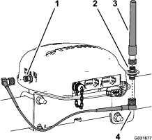
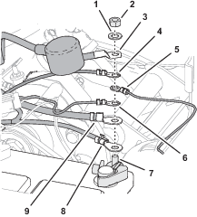
Assemble the following wire and cable terminals onto the threaded post of the positive battery terminal (Figure 94) in the following order:
Important: Ensure that the battery-cable terminal (positive) to the engine starter is positioned at the top of the stack of terminals on the threaded post.
-
Ring terminal—165 cm (65 inch) modem power harness branch (labeled
-
Battery-cable terminal (positive)—to the alternator (50 A)
-
Ring terminal—258 cm (101-1/2 inch) navigation-data and electrical harness branch (labeled )
-
Ring terminal—21.6 cm (8-1/2 inch) machine harness branch (labeled )
-
Ring terminal—24 cm (9-1/2 inch) kit sprayer-harness branch (unlabeled)
-
Battery-cable terminal (positive)—to the engine starter
-
-
Assemble the hex nut (1/4 inch) and washer (1/4 inch) onto the threaded post, and torque the nut to 1017 to 1234 N∙cm (90 to 110 in-lb).
-
Align the insulator cover of the positive battery cable to the starter over the threaded post (Figure 94).
-
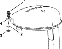
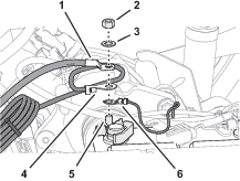
Assemble the following wire and cable terminals onto the threaded post of the negative battery terminal (Figure 95) in the following order:
Important: Ensure that the battery-cable terminal (negative) to the engine and chassis ground is positioned at the top of the stack of terminals on the threaded post.
-
Ring terminal—258 cm (101-1/2 inch) navigation-data and electrical harness branch (not labeled—black wire insulation)
-
Ring terminal—165 cm (65 inch) modem power harness branch (labeled )
-
Battery-cable terminal (negative)—to the engine and chassis ground
-
Assembling the Rear GeoLink Harness, Navigation-Data and Electrical Harness, and Modem Power Harness to the Battery Cables
Note: If you need additional terminal holding capacity for the battery clamp, order and install optional battery-clamp bolt Toro Part No. 122-9921.
-
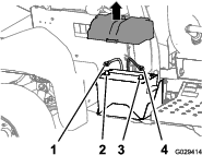
Route the positive terminal (red wire), negative terminal (black wire), and fuses block (50 A) of the rear wire harness up between the battery box and the chassis of the machine (Figure 97).
-
Route the positive terminal (red wire), negative terminal (black wire), and 10 A fuse block of the navigation-electrical harness up between the battery box and the chassis of the machine.
-
Route the ring terminals labeled and of the modem power harness up between the battery box and the chassis of the machine.
-
Remove the T-bolts and hex nuts from the terminals of the positive and negative battery cables (Figure 97).
-
Assemble a T-bolt through the positive terminal (red wire) of the rear wire harness, the positive terminal of the navigation-electrical harness, modem power harness, and terminal of the positive battery cable (Figure 97).
-
Loosely secure the terminals and the T-bolt with a hex nut (Figure 97).
-
Assemble a T-bolt through the negative terminal (black wire) of the rear wire harness, the negative terminal of the navigation-electrical harness, modem power harness, and terminal of the negative battery cable (Figure 97).
-
Loosely secure the terminals and the T-bolt with a hex nut (Figure 97).
Connecting the Battery
-
Connect the positive (red) cable to the positive (+) battery post, and tighten the nut; refer to Figure 97 in Assembling the Rear GeoLink Harness, Navigation-Data and Electrical Harness, and Modem Power Harness to the Battery Cables.
-
Connect the negative (black) cable to the negative (–) battery post, and tighten the nut; refer to Figure 97 in Assembling the Rear GeoLink Harness, Navigation-Data and Electrical Harness, and Modem Power Harness to the Battery Cables.
-
Slide the insulator boots over both battery posts.
-
Install the battery cover and secure it with the strap; refer to Figure 32 in Disconnecting the Battery.
Securing the Data Harness
-
Gather the excess length of the data harness against the right, upper-frame tube (Figure 98).
-
Align the data harness to the shock-support tube, and secure the harness to the tube with a cable tie (Figure 98).
-
Align the data-harness bundle to the right, upper-frame tube, and secure the harness bundle to the frame tube with a cable tie (Figure 98).
-
Ensure that there is clearance between the pulleys and belts and the data harness, battery harness, kit wire harness, and battery cables.
Secure the wire harness and cables with cable ties as needed to provide clearance away from the belts and pulleys.
Installing the Right Front Fender
Note: Replace damaged the push-in fasteners with Toro Part No. 117-2382.
-
Align the inner-fender shroud to the right, upper and right, lower-frame tubes (Figure 99).
-
Secure the inner-fender shroud to the frame tubes (Figure 99) with the 6 push-in fasteners and 5 washers (9/16 x 1/2 inch).
-
Align the right, front fender to the machine as shown Figure 100, and align the holes in the fender with the holes in the frame.
-
Secure right, front fender to the clip nut of the cross-member support (Figure 100) with the capscrew (5/16 x 1 inch) and washer (5/16 inch).
-
Secure the right, front fender to the roll bar mounting channel with 2 push-in fasteners (Figure 101).
-
Align the hole in the right, front fender with the hole in the platform floor (Figure 102), and secure the fender to the floor with a capscrew (5/16 x 1 inch) and washer (5/16 inch).
-
Align the hole in the bottom console cover to the hole in the shock-support tube and the hole in the end console cover to the hole in the cross-member tube (Figure 103).
-
Secure the covers to the tubes (Figure 103) with 2 capscrews (5/16 x 1 inch) and 2 washers (5/16 inch).
Installing the Engine-Access Panel and the Seat
Installing the Engine-Access Panel
Installing the Seat
-
Align the seat and seat plate to the chassis of the machine (Figure 105).
-
Align the holes in the pivot fittings of the seat pan with the holes in the chassis bracket (Figure 106).
-
Assemble the seat pan to the chassis brackets with the 2 pivot pins (Figure 106).
-
Secure the pivot pins to the machine with the 2 hairpins (Figure 106).
-
Assemble the prop rod to the bracket of the seat with the washer and hairpin (Figure 107).
-
Plug the 2-socket connector of the machine wire harness into the connector for the seat switch until the connectors latch securely (Figure 108).
-
Rotate the seat forward slightly, remove the prop rod from the detent, rotate the seat down until the seat latches securely.
Completing the Installation of the CL-55 Modem Kit
Closing the Seats
Move the prop rods for the seats into the slots and tilt the seats down.
Powering the GeoLink Components
-
Turn the ignition key to the RUN (gasoline) or PREHEAT/RUN (diesel) position.
-
Verify that the following components indicate that each receives power:
-
Turn the ignition key to the OFF position.
-
Verify that power is shut off at the following components:
-
Control console
-
Satellite receiver
-
Automatic section controller
-

Configuring the GPS Correction Source
Changing the N-Trip Source
-
Turn the ignition key to the ON position.
-
On the home screen, press the SETUP icon.
-
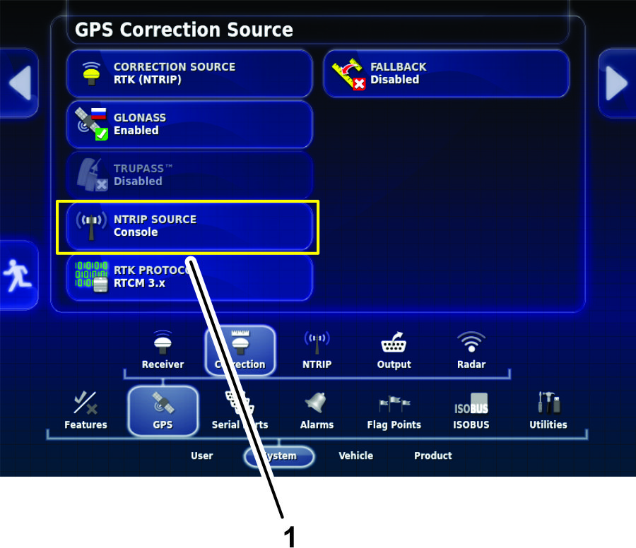
On the setup screen, press the SYSTEM icon, the GPS icon, and the CORRECTION icon (Figure 114).
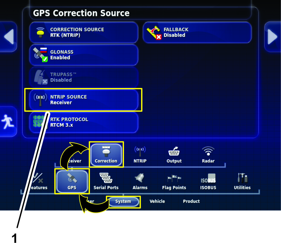
-
On the GPS Correction Source screen, press the NTRIP SOURCE icon (Figure 114).
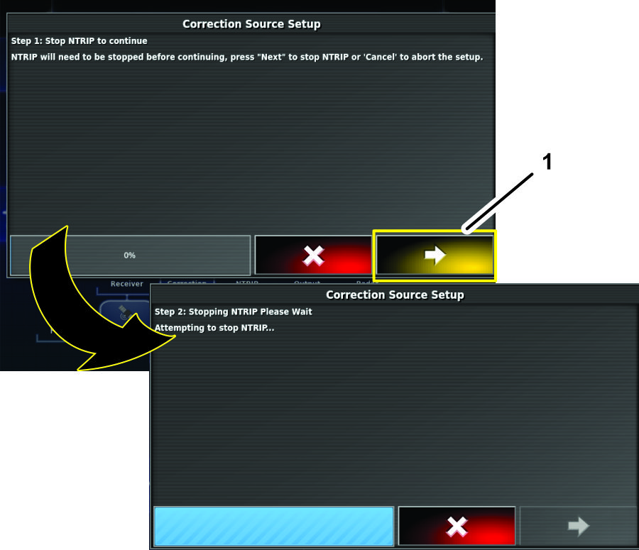
-
When the Correction Source Setup wizard displays, press the next icon (Figure 115).
-
In the NTrip Source dialog box, press the CONSOLE icon then press the confirm icon (Figure 116).
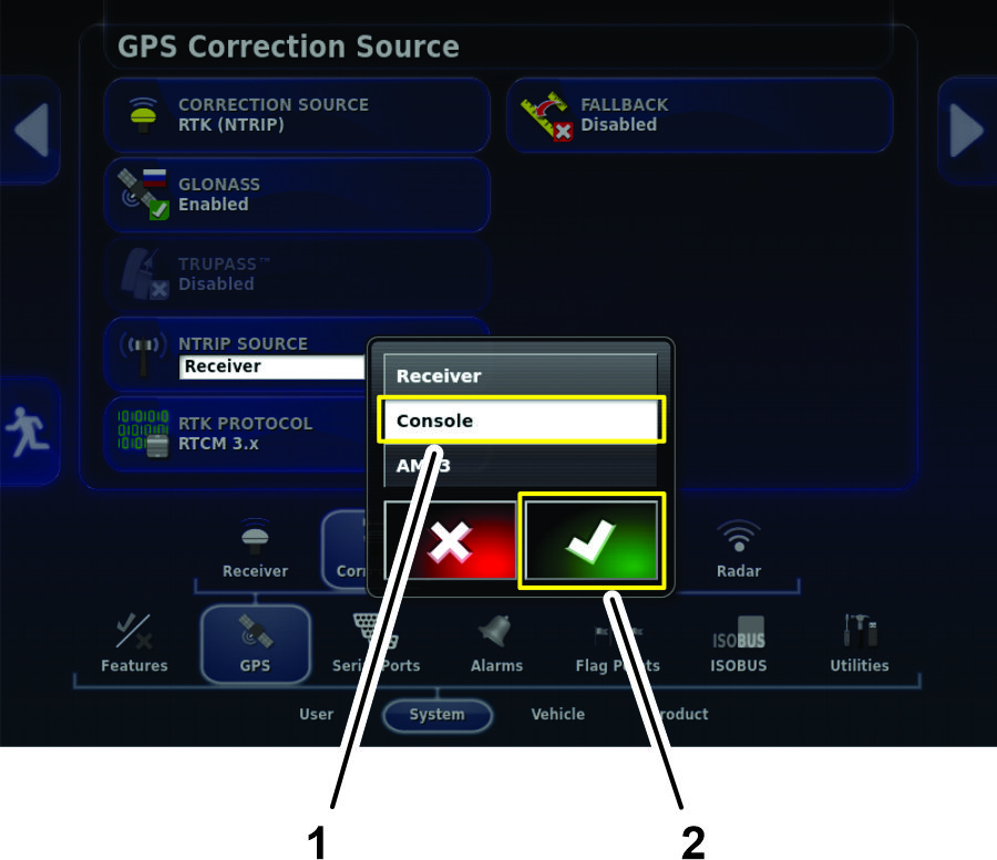
Note: The NTRIP SOURCE icon displays the console source (Figure 117).
Creating a Spray Job
-
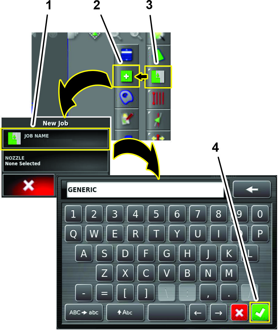
Press the Job Menu and press the CREATE NEW JOB icon (Figure 118).
-
Use on-screen keyboard to type a name for the generic job, and press the confirm icon (Figure 118).
-
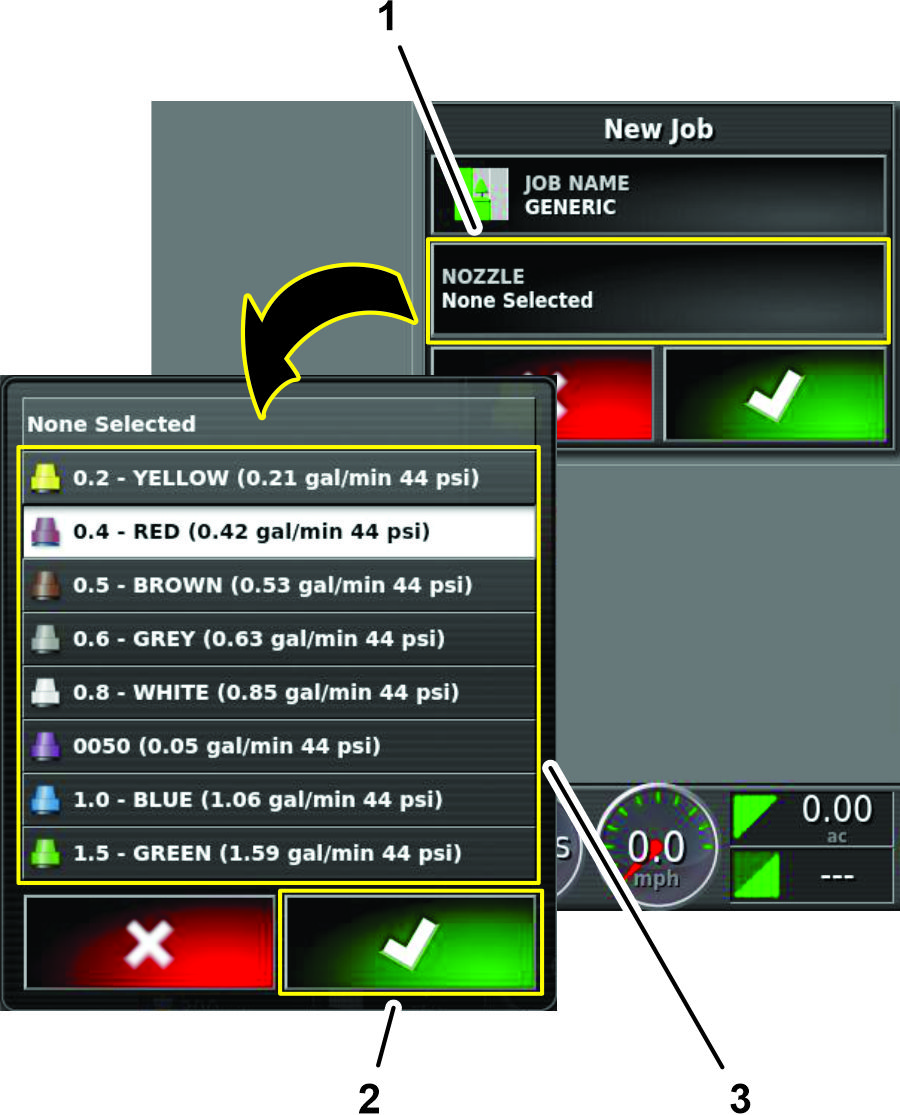
In the new job dialog box, press the NOZZLE icon (Figure 119).
-
In the nozzle selection list, press any nozzle icon, and press the confirm icon (Figure 119).
-
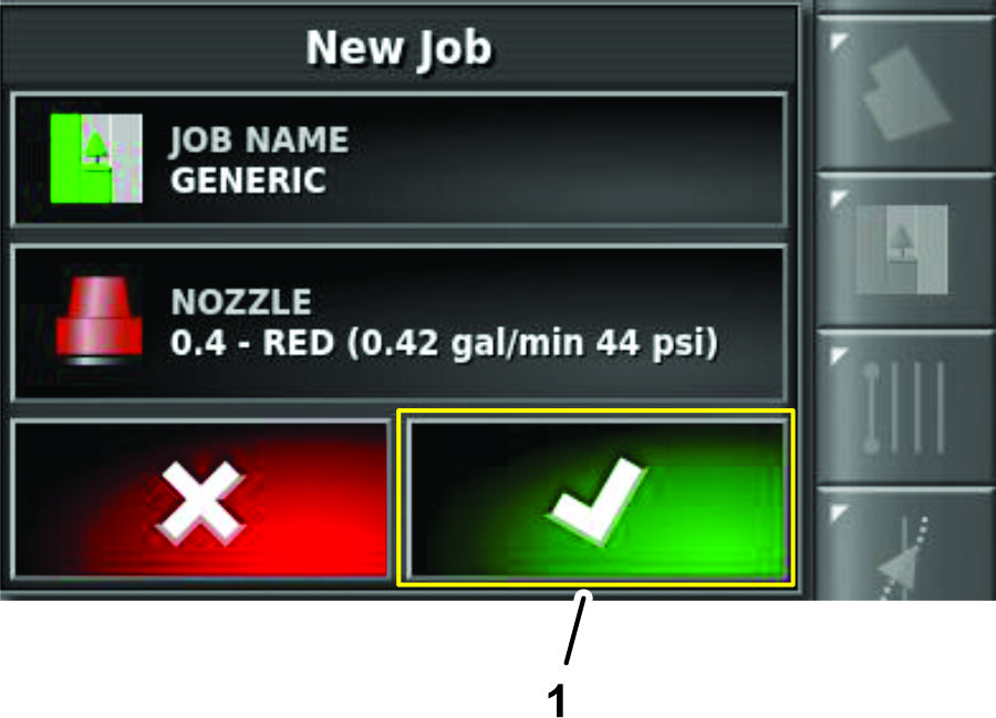
In the new job dialog box, press the confirm icon (Figure 120).
Verifying the Cellular Status
-
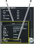
Press the SYSTEM INFORMATION icon, and then swipe the FULL SCREEN icon in the upper right corner of the system information window (Figure 121).
-
In the system information screen, use the scroll bar to navigate to the CL55 icon (Figure 122).
-
Press the CL55 icon to display the signal strength information.(Figure 122), and verify that the modem signal strength is between -60 dBm and -99 dBm.
Note: If the modem signal is equal to or less than -100 dBm, contact your authorized Toro distributor, Toro NSN at 1-844-GEOLINK (1-844-436-5465), or NSNTech@toro.com for customer service.
-
Swipe the FULL SCREEN icon to minimize the system information screen.
Performing a Compass Calibration
Perform a compass calibration at the distributor’s location; refer to Calibrating the Compass in the Operator’s Manual or Software Guide for your GeoLink system.
Clearing NVRAM
Changing the Setup Screen for Dealer Access
Important: You must erase the nonvolatile RAM at the customer location.
-
Contact Toro NSN at 1-844-GEOLINK (1-844-436-5465) or NSNTech@toro.com for customer service to request the dealer access level password.
-
Rotate the ignition key to the ON position.
-
Press the SETUP icon on the main screen (Figure 123).
-
In the setup screen, press the USER icon and the ACCESS LEVEL icon(Figure 124).
-
Press the PASSWORD icon (Figure 124).
-
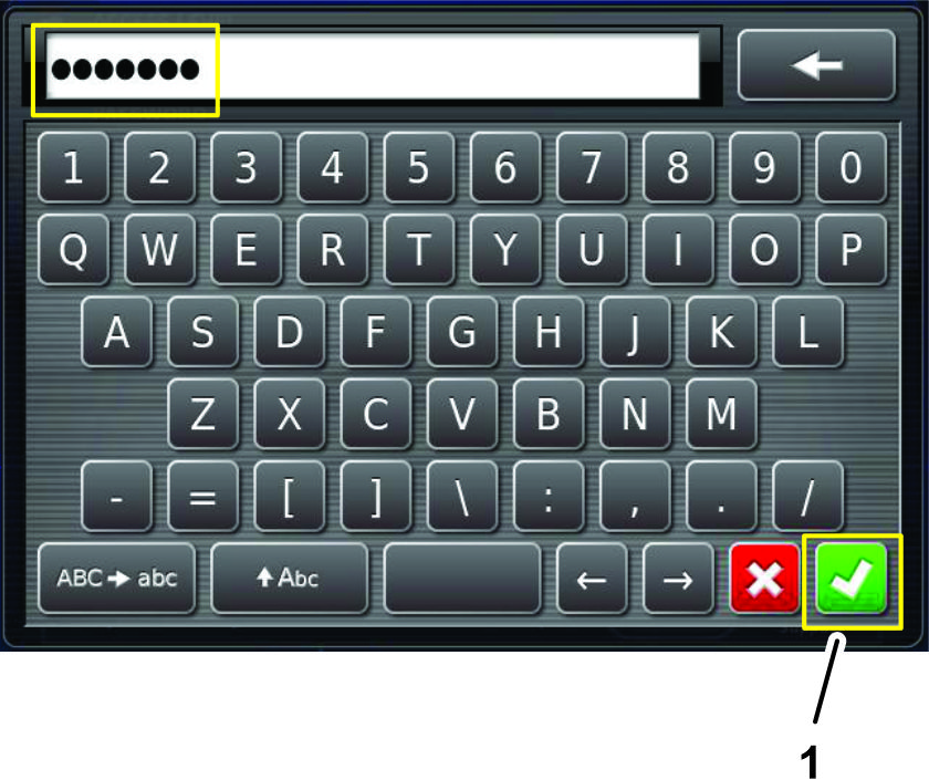
Use the on-screen keyboard to enter the password that you received in step 1, and press the confirm icon (Figure 125).
Note: The user access level screen displays the DEALER icon (Figure 126).

Erasing the Nonvolatile RAM
-
In the setup screen, press the SYSTEM icon, GPS icon, and ADVANCED CONFIGURATION icon (Figure 127).

-
In the GPS Advanced Configuration screen, press the RESET NVRAM icon (Figure 127).
-
In the GPS receive warning dialog box, press the YES icon (Figure 127).
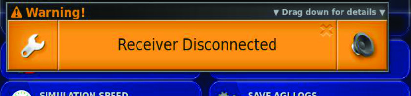
Note: The receiver disconnected warning (Figure 128) displays briefly.
-
Wait 2 minutes for the satellite receiver and modem startup.
-
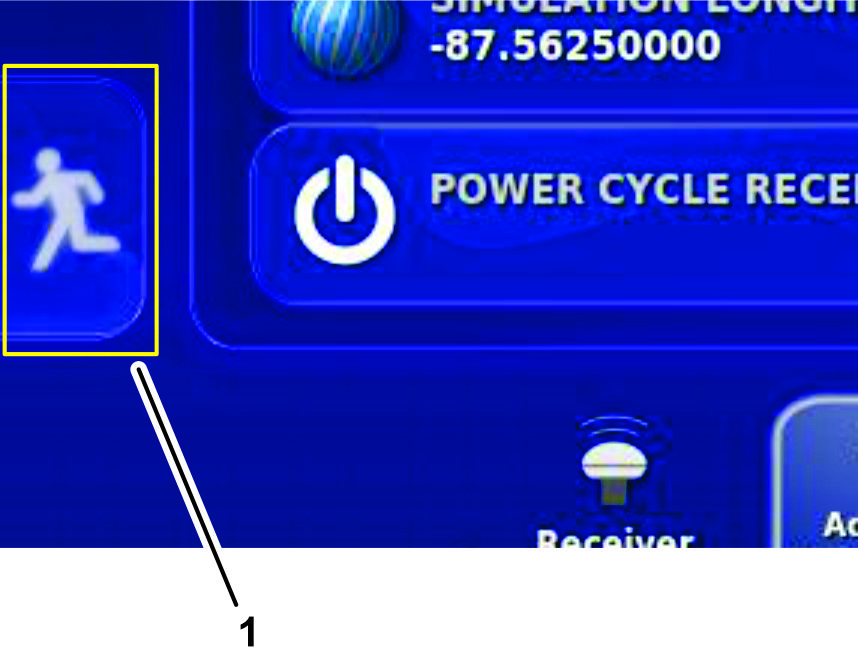
Press the EXIT SETUP icon (Figure 129).
Changing the User Access Level to Standard Mode
-
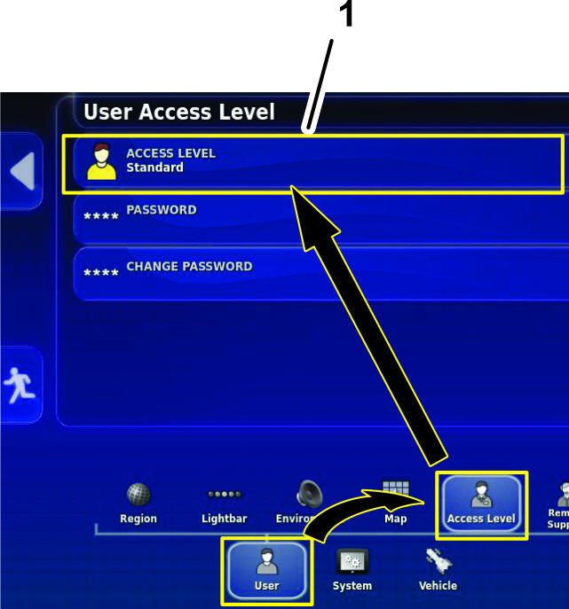
On the setup screen, press the USER icon, press the ACCESS LEVEL icon (Figure 130).
-
In the user access level dialog box, change the access level to STANDARD.
-
Rotate the ignition switch to the OFF position and remove the key.
Performing a Compass Calibration
Perform a compass calibration at the customer’s location; refer to Calibrating the Compass in the Operator’s Manual or Software Guide for your GeoLink system.