| Maintenance Service Interval | Maintenance Procedure |
|---|---|
| Before each use or daily |
|
Introduction
This machine is a ride-on, rotary-blade lawn mower intended to be used by professional, hired operators in commercial applications. It is primarily designed for cutting grass on well-maintained lawns in parks, sports fields, and on commercial grounds. It is not designed for cutting brush, mowing grass and other growth alongside highways, or for agricultural uses. Using this product for purposes other than its intended use could prove dangerous to you and bystanders.
Read this information carefully to learn how to operate and maintain your product properly and to avoid injury and product damage. You are responsible for operating the product properly and safely.
Visit www.Toro.com for product safety and operation training materials, accessory information, help finding a dealer, or to register your product.
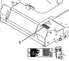
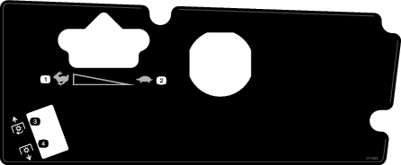
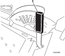
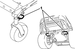
Whenever you need service, genuine Toro parts, or additional information, contact an Authorized Service Dealer or Toro Customer Service and have the model and serial numbers of your product ready. Figure 1 identifies the location of the model and serial numbers on the product. Write the numbers in the space provided.
Important: With your mobile device, you can scan the QR code on the serial number decal (if equipped) to access warranty, parts, and other product information.
This manual identifies potential hazards and has safety messages identified by the safety-alert symbol (Figure 2), which signals a hazard that may cause serious injury or death if you do not follow the recommended precautions.

This manual also uses 2 words to highlight information. Important calls attention to special mechanical information and Note emphasizes general information worthy of special attention.
It is a violation of California Public Resource Code Section 4442 or 4443 to use or operate the engine on any forest-covered, brush-covered, or grass-covered land unless the engine is equipped with a spark arrester, as defined in Section 4442, maintained in effective working order or the engine is constructed, equipped, and maintained for the prevention of fire.
The enclosed engine owner's manual is supplied for information regarding the US Environmental Protection Agency (EPA) and the California Emission Control Regulation of emission systems, maintenance, and warranty. Replacements may be ordered through the engine manufacturer.
Warning
CALIFORNIA
Proposition 65 Warning
Diesel engine exhaust and some of its constituents are known to the State of California to cause cancer, birth defects, and other reproductive harm.
Battery posts, terminals, and related accessories contain lead and lead compounds, chemicals known to the State of California to cause cancer and reproductive harm. Wash hands after handling.
Use of this product may cause exposure to chemicals known to the State of California to cause cancer, birth defects, or other reproductive harm.
Safety
This machine has been designed in accordance with ANSI B71.4-2017.
General Safety
This product is capable of amputating hands and feet and of throwing objects. Always follow all safety instructions to avoid serious personal injury.
-
Read and understand the contents of this Operator’s Manual before starting the engine.
-
Use your full attention while operating the machine. Do not engage in any activity that causes distractions; otherwise, injury or property damage may occur.
-
Do not operate the machine without all guards and other safety protective devices in place and functioning properly on the machine.
-
Keep your hands and feet away from rotating parts. Keep clear of the discharge opening.
-
Keep bystanders and children out of the operating area. Never allow children to operate the machine.
-
Shut off the engine, remove the key (if equipped), and wait for all movement to stop before you leave the operator’s position, Allow the machine to cool before adjusting, servicing, cleaning, or storing it.
Improperly using or maintaining this machine can result in injury.
To reduce the potential for injury, comply with these safety instructions
and always pay attention to the safety-alert symbol  , which means Caution, Warning,
or Danger—personal safety instruction. Failure to comply with
these instructions may result in personal injury or death.
, which means Caution, Warning,
or Danger—personal safety instruction. Failure to comply with
these instructions may result in personal injury or death.
Engine-Emission Certification
The engine in this machine is EPA Tier 4 Final and EU Stage V emissions compliant.
Safety and Instructional Decals
 |
Safety decals and instructions are easily visible to the operator and are located near any area of potential danger. Replace any decal that is damaged or missing. |


Setup
Raising the Roll Bar
Raise the roll bar; refer to Adjusting the Roll Bar.
Installing the Cutting Unit
Parts needed for this procedure:
| Cutting unit Installation Instructions | 1 |
Install the cutting unit using the Installation Instructions for that cutting unit.
Adjusting the Left, Front Caster Wheel
Adjust the left, front caster wheel to the outside position for 72-inch cutting units and to the inside position for 60-inch and 62-inch cutting units.
Checking the Tire Pressure
Check the tire pressure; refer to Checking the Tire Pressure.
Important: Maintain pressure in all tires to ensure a good quality-of-cut and proper machine performance. Do not underinflate the tires.
Checking the Fluid Levels
-
Check the hydraulic-fluid level before starting the engine, refer to Checking the Hydraulic System.
-
Check the engine-oil level before starting the engine, refer to Checking the Engine-Oil Level.
-
Check the cooling system before starting the engine; refer to Checking the Cooling System .
Product Overview
Note: Determine the left and right sides of the machine from the normal operating position.
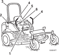
Become familiar with all the controls before you start the engine and operate the machine (Figure 3 and Figure 4).
Motion-Control Levers
The motion-control levers control the forward and rearward motions as well as the turning of the machine. Refer to Driving the Machine.
Parking-Brake Lever
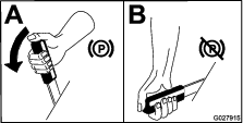
Whenever you shut off the engine, engage the parking brake to prevent accidental movement of the machine. To engage the parking brake, pull the parking-brake lever rearward and up (Figure 5). To release the parking brake, push the parking-brake lever forward and down.
Ignition Switch
The ignition switch has 3 positions: OFF, ON/PREHEAT, and START.
Throttle Lever
The throttle lever controls the speed of the engine, the speed of the blades, and, in conjunction with motion-control levers, the ground speed of the machine. Moving the throttle lever forward toward the FAST position increases the engine speed. Moving it rearward toward the SLOW position decreases the engine speed. Always run the machine with the throttle in the FAST position when cutting grass.
Power-Takeoff (PTO) Switch
The power-takeoff (PTO) switch starts and stops the mower blades.
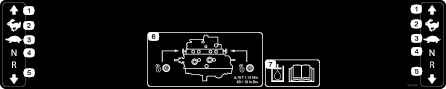
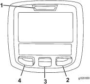
Using the InfoCenter LCD Display
The InfoCenter LCD display shows information about your machine such as the operating status, various diagnostics and other information about the machine (Figure 6). There is a splash screen and main information screen of the InfoCenter. You can switch between the splash screen and main information screen, at any time, by pressing any of the InfoCenter buttons and then selecting the appropriate directional arrow.
-
Left Button, Menu Access/Back Button—press this button to access the InfoCenter menus. You can use it to back out of any menu you are currently using.
-
Middle Button—use this button to scroll down menus.
-
Right Button—use this button to open a menu where a right arrow indicates additional content.
Note: The purpose of each button may change depending on what is required at the time. Each button is labeled with an icon displaying its current function.
| SERVICE DUE | Indicates when scheduled service should be performed |
| RPM | Engine RPM/status—indicates the engine RPM |
 | Hour meter |
 | Info icon |
 | Stationary regeneration required |
 | Glow plugs are active |
 | Operator must sit in seat |
 | Parking Brake Indicator—indicates when the parking brake is on |
 | Coolant Temperature-indicates the engine coolant temperature in either °C or °F |
 | Temperature (hot) |
 | Denied or not allowed |
 | Engine start |
 | Stop or shutdown |
 | Engine |
 | Key switch |
 | PIN code |
 | CAN bus |
 | InfoCenter |
 | Bad or failed |
 | Bulb |
 | High: over allowed range |
 | Low: under allowed range |
| / | Out of range |
 | Switch |
 | Operator must release switch |
 | Operator should change to indicated state |
| Symbols are often combined to form sentences. Some examples are shown below | |
 | Engine start denied |
 | Engine shutdown |
 | Engine coolant too hot |
 | Sit down or set parking brake |
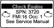
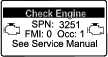
 | DPF ash accumulation notification. Refer to Servicing the Diesel-Oxidation Catalyst (DOC) and the Soot Filter for details. |
 | Reset-standby regeneration request |
| Parked or recovery regeneration request | |
 | A parked or recovery regeneration is processing. |
 | High exhaust temperature |
 | NOx control diagnosis malfunction; drive the machine back to the shop and contact your authorized Toro distributor (software version F and later). |
Using the Menus
To access the InfoCenter menu system, press the menu access button while at the main screen. This brings you to the main menu. Refer to the following tables for a synopsis of the options available from the menus:
| Main Menu | |
| Menu Item | Description |
| Faults | The Faults menu contains a list of the recent machine faults. Refer to the Service Manual or your Authorized Toro Distributor for more information on the Faults menu and the information contained there. |
| Service | The Service menu contains information on the machine such as hours of use and other similar numbers. |
| Settings | The Settings menu allows you to customize and modify configuration variables on the InfoCenter display. |
| About | The About menu lists the model number, serial number, and software version of your machine. |
| Service | |
| Menu Item | Description |
| Hours | Lists the total number of hours that the machine, engine and fan have been on, as well as the number of hours the machine has been transported and has overheated. |
| Settings | |
| Menu Item | Description |
| Units | Controls the units used on the InfoCenter. The menu choices are English or Metric |
| Language | Controls the language used on the InfoCenter*. |
| LCD Backlight | Controls the brightness of the LCD display. |
| LCD Contrast | Controls the contrast of the LCD display. |
| Protected Menus | Allows a person authorized by your company with the PIN code to access protected menus. |
* Only "operator-faced" text is translated. Faults, Service, and Diagnostics screens are "service-faced." Titles will be in the selected language, but menu items are in English.
| About | |
| Menu Item | Description |
| Model | Lists the model number of the machine. |
| SN | Lists the serial number of the machine. |
| Machine Controller Revision | Lists the software revision of the master controller. |
| InfoCenter Revision | Lists the software revision of the InfoCenter. |
| CAN Bus | Lists the machine communication bus status. |
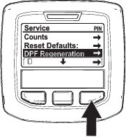
Protected Menus
There is 1 operating function that is accessed within the Service Menu of the InfoCenter: Regeneration request; refer to Accessing the DPF Regeneration Menus. This function is in the Protected Menu.
Accessing Protected Menus
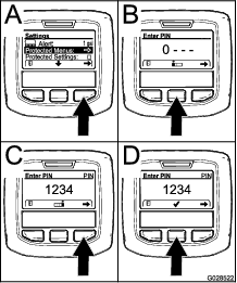
Note: The factory default PIN code for you machine is either 0000 or 1234.If you changed the PIN code and forgot the code, contact your authorized Toro distributor for assistance.
-
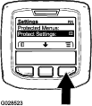
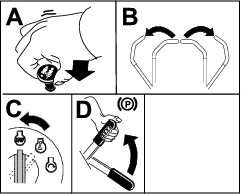
From the MAIN MENU, use the center button to scroll down to the SETTINGS MENU and press the right button (Figure 7).
-
In the SETTINGS MENU, use the center button to scroll down to the PROTECTED MENU and press the right button (Figure 8A).
-
To enter the PIN code, press the center button until the correct first digit appears, then press the right button to move on to the next digit (Figure 8B and Figure 8C). Repeat this step until the last digit is entered and press the right button once more.
-
Press the middle button to enter the PIN code (Figure 8D).
Wait until the red indicator light of the InfoCenter illuminates.
Note: If the InfoCenter accepts the PIN code and the protected menu is unlocked, the word “PIN” displays in the upper right corner of the screen.
Note: Rotate the key switch to the OFF position and then to the ON position locks the protected menu.
You can view and change the settings in the Protected Menu. Once you access the Protected Menu, scroll down to Protect Settings option. Use the right button to change the setting. Setting the Protect Settings to OFF allows you to view and change the settings in the Protected Menu without entering the PIN code. Setting the Protect Settings to ON hides the protected options and requires you to enter the PIN code to change the setting in the Protected Menu. After you set the PIN code, rotate the key switch OFF and back to the ON position to enable and save this feature.
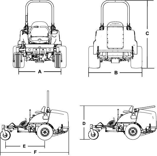
| Description | Figure 9 reference | Dimension or Weight | |
| Height with roll bar up | C | 183 cm (72 inches) | |
| Height with roll bar down | D | 125 cm (49 inches) | |
| Overall length | F | 253 cm (99-1/2 inches) | |
| Overall width | B | 145 cm (57 inches) | |
| Wheel base | E | 145 cm (57-1/4 inches) | |
| Wheel tread (tire center to center) rear | A | 114 cm (45 inches) | |
| Ground clearance | 10 cm (4 inches) | ||
| Weight, with 72-inch Side-Discharge Cutting unit (30354 or 30481) | 1052 kg (2,320 lb) | ||
| Weight, with 60-inch Side-Discharge Cutting unit (30456) | 1036 kg (2,284 lb) | ||
| Weight, with 72-inch Base Cutting unit (30353) | 1012 kg (2,231 lb) | ||
| Weight, with 62-inch Base Cutting unit (30457) | 990 kg (2,183 lb) | ||
| Weight with the 100-inch Rear-Discharge Cutting unit (31101) | 1200 kg (2,646 lb) | ||
Note: Specifications and design are subject to change without notice.
Attachments/Accessories
A selection of Toro approved attachments and accessories is available for use with the machine to enhance and expand its capabilities. Contact your Authorized Service Dealer or authorized Toro distributor or go to www.Toro.com for a list of all approved attachments and accessories.
To ensure optimum performance and continued safety certification of the machine, use only genuine Toro replacement parts and accessories. Replacement parts and accessories made by other manufacturers could be dangerous, and such use could void the product warranty.
Operation
Note: Determine the left and right sides of the machine from the normal operating position.
Before Operation
Before Operation Safety
General Safety
-
Never allow children or untrained people to operate or service the machine. Local regulations may restrict the age of the operator. The owner is responsible for training all operators and mechanics.
-
Become familiar with the safe operation of the equipment, operator controls, and safety signs.
-
Shut off the engine, remove the key (if equipped), and wait for all movement to stop before you leave the operator’s position, Allow the machine to cool before adjusting, servicing, cleaning, or storing it.
-
Know how to stop the machine and shut off the engine quickly.
-
Check that operator-presence controls, safety switches, and guards are attached and functioning properly. Do not operate the machine unless they are functioning properly.
-
Before mowing, always inspect the machine to ensure that the blades, blade bolts, and cutting assemblies are in good working condition. Replace worn or damaged blades and bolts in sets to preserve balance.
-
Inspect the area where you will use the machine and remove all objects that the machine could throw.
Fuel Safety
-
Use extreme care in handling fuel. It is flammable and its vapors are explosive.
-
Extinguish all cigarettes, cigars, pipes, and other sources of ignition.
-
Use only an approved fuel container.
-
Do not remove the fuel cap or fill the fuel tank while the engine is running or hot.
-
Do not add or drain fuel in an enclosed space.
-
Do not store the machine or fuel container where there is an open flame, spark, or pilot light, such as on a water heater or other appliance.
-
If you spill fuel, do not attempt to start the engine; avoid creating any source of ignition until the fuel vapors have dissipated.
Adding Fuel
Fuel Specification
Important: Use only ultra-low sulphur diesel fuel. Fuel with higher rates of sulfur degrades the diesel oxidation catalyst (DOC), which causes operational problems and shortens the service life of engine components.Failure to observe the following cautions may damage the engine.
-
Never use kerosene or gasoline instead of diesel fuel.
-
Never mix kerosene or used engine oil with the diesel fuel.
-
Never keep fuel in containers with zinc plating on the inside.
-
Do not use fuel additives.
Petroleum Diesel
Cetane rating: 45 or higher
Sulfur content: Ultra-low sulfur (<15 ppm)
| Diesel fuel specification | Location |
| ASTM D975 | USA |
| No. 1-D S15 | |
| No. 2-D S15 | |
| EN 590 | European Union |
| ISO 8217 DMX | International |
| JIS K2204 Grade No. 2 | Japan |
| KSM-2610 | Korea |
-
Use only clean, fresh diesel fuel or biodiesel fuels.
-
Purchase fuel in quantities that can be used within 180 days to ensure fuel freshness.
Use summer-grade diesel fuel (No. 2-D) at temperatures above -7°C (20°F) and winter-grade fuel (No. 1-D or No. 1-D/2-D blend) below that temperature.
Note: Use of winter-grade fuel at lower temperatures provides lower flash point and cold flow characteristics which eases starting and reduces fuel filter plugging.Using summer-grade fuel above -7°C (20°F) contributes toward longer fuel pump life and increased power compared to winter-grade fuel.
Using Biodiesel
This machine can also use a biodiesel-blended fuel of up to B20 (20% biodiesel, 80% petrodiesel).
Sulfur content: Ultra-low sulfur (<15 ppm)
Biodiesel fuel specification: ASTM D6751 or EN14214
Blended fuel specification: ASTM D975, EN590, or JIS K2204
Important: The petroleum diesel portion must be ultra-low sulfur.
Observe the following precautions:
-
Biodiesel blends may damage painted surfaces.
-
Use B5 (biodiesel content of 5%) or lesser blends in cold weather.
-
Monitor seals, hoses, gaskets in contact with fuel as they may degrade over time.
-
Fuel filter plugging may occur for a time after you convert to biodiesel blends.
-
For more information on biodiesel, contact your authorized Toro distributor.
Fuel Tank Capacity
43.5 L (11.5 US gallons)
Filling the Fuel Tank
Important: The fuel tanks are connected, but the fuel does not transfer quickly from one tank to the other. It is important when filling that you park on a level surface. If you park on a hill, you may inadvertently overfill the tanks.
Important: Do not overfill the fuel tanks.
Important: Do not open the fuel tanks when parked on a hill. The fuel could spill out.
Note: If possible, fill the fuel tanks after each use. This minimizes buildup of condensation inside the fuel tank.
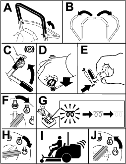
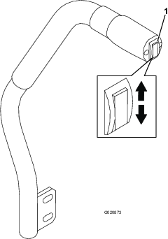
Adjusting the Roll Bar
Warning
To avoid injury or death from rollover, keep the roll bar in the raised locked position and use the seat belt.
Ensure that the seat is secured with the seat latch.
Warning
There is no rollover protection when the roll bar is in the down position.
-
Do not operate the machine on uneven ground or on a hill side with the roll bar in the down position.
-
Lower the roll bar only when absolutely necessary.
-
Do not wear the seat belt when the roll bar is in the down position.
-
Drive slowly and carefully.
-
Raise the roll bar as soon as clearance permits.
-
Check carefully for overhead clearances (i.e., branches, doorways, electrical wires) before driving under any objects and do not contact them.
Important: Always use the seat belt when the roll bar is in the raised and locked position. Do not use the seat belt when the roll bar is in the lowered position.
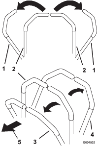
Lowering the Roll Bar
Lower the roll bar as shown in Figure 12.
Note: Push the bar forward to relieve pressure on the pins.
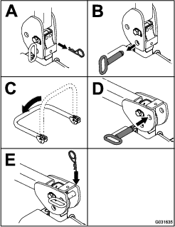
Note: Secure the roll bar so that it does not damage the hood.
Raising the Roll Bar
Raise the roll bar as shown in Figure 11.
Important: Always use the seat belt when the roll bar is in the raised and locked position. Do not use the seat belt when the roll bar is in the lowered position.
Adjusting the Height of Cut
You can adjust the height of cut from 2.5 to 15.8 cm (1 to 6 inches) in 6 mm (1/4 inch) increments by relocating the stop pin into different hole locations.
-
With the engine running, push the deck-lift switch up until the cutting unit is fully raised and release the switch immediately (Figure 24).
-
Rotate the stop pin until the roll pin in it lines up with the slots in the holes in the height-of-cut bracket and remove it (Figure 13).
-
Select a hole in the height-of-cut bracket corresponding to the height of cut desired, insert the pin, and rotate it down to lock it in place (Figure 13).
Note: There are 4 rows of hole positions (Figure 13). The top row gives you the height of cut listed above the pin. The second row down gives you the height listed plus 6 mm (1/4 inch). The third row down gives you the height listed plus 12 mm (1/2 inch). The bottom row gives you the height listed plus 18 mm (3/4 inch). For the 15.8 cm (6 inch) position, there is only 1 hole, located in the second row. This does not add 6 mm (1/4 inch) to the 15.8 cm (6 inch) position.
-
Adjust the anti-scalp rollers and skids as required.
Using the Safety-Interlock System
Caution
If the safety-interlock switches are disconnected or damaged, the machine could operate unexpectedly, causing personal injury.
-
Do not tamper with the interlock switches.
-
Check the operation of the interlock switches daily and replace any damaged switches before operating the machine.
Understanding the Safety-Interlock System
The safety-interlock system prevents the engine from starting unless:
-
You are sitting on the seat or the parking brake is engaged.
-
The power takeoff (PTO) is disengaged.
-
The motion-control levers are in the NEUTRAL-LOCK position.
-
The engine temperature is below the maximum operating temperature.
The safety-interlock system also shuts off the engine when you move the traction controls from the NEUTRAL-LOCK position with the parking brake engaged. If you rise from the seat when the PTO is engaged, there is a 1-second delay and then the engine shuts off.
Testing the Safety-Interlock System
Test the safety-interlock system before you use the machine each time. If the safety system does not operate as described below, have an Authorized Service Dealer repair the safety system immediately.
-
Sit on the seat, engage the parking brake, and move the PTO to the ON position. Try starting the engine; the engine should not crank.
-
Sit on the seat, engage the parking brake, and move the PTO to the OFF position. Move either motion-control lever out of the NEUTRAL-LOCK position. Try starting the engine; the engine should not crank. Repeat for other motion-control lever.
-
Sit on the seat, engage the parking brake, move the PTO switch to the OFF position, and move the motion-control levers to the NEUTRAL-LOCK position. Start the engine. While the engine is running, release the parking brake, engage the PTO, and rise slightly from the seat; the engine should shut off within 2 seconds.
-
Without an operator on the seat, engage the parking brake, move the PTO switch to the OFF position, and move the motion-control levers to the NEUTRAL-LOCK position. Start the engine. While the engine is running, center either motion control; the engine should shut off within 2 seconds. Repeat for the other motion-control lever.
-
Without an operator on the seat, disengage the parking brake, move the PTO switch to the OFF position, and move the motion-control levers to the NEUTRAL-LOCK position. Try starting the engine; the engine should not crank.
Using the SCM to Diagnose System Problems
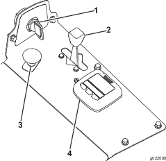
The machine is equipped with a standard control module (SCM) monitoring system that tracks the function of various key systems. The SCM is located under the right control panel. Access it through the side panel cover (Figure 14). To open the side panel cover, release the 2 latches and pull out on it.
On the face of the SCM are 11 LEDs that illuminate to indicate various system conditions. You can use 7 of these lights for system diagnosis. Refer to Figure 15 for a description of what each light means. For details on using the rest of the SCM functions, refer to the Service Manual, available through your Authorized Toro Distributor.
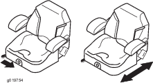
Positioning the Seat
The seat moves forward and backward. Position the seat where you have the best control of the machine and are most comfortable.
To adjust, move the lever sideways to unlock the seat (Figure 16).
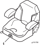
Changing the Seat Suspension
The seat is adjustable to provide a smooth and comfortable ride. Position the seat where you are most comfortable.
To adjust it, turn the knob in front either direction to provide the best comfort (Figure 17).
Unlatching the Seat
To access the hydraulic and other systems under the seat, unlatch the seat and swing it forward.
-
Use the seat position adjustment lever to slide the seat all the way forward.
-
Pull the seat latch forward and lift up to unlatch the seat (Figure 18).
During Operation
During Operation Safety
General Safety
-
The owner/operator can prevent and is responsible for accidents that may cause personal injury or property damage.
-
Wear appropriate clothing, including eye protection; long pants; substantial, slip-resistant footwear; and hearing protection. Tie back long hair and do not wear loose clothing or loose jewelry.
-
Do not operate the machine while ill, tired, or under the influence of alcohol or drugs.
-
Use your full attention while operating the machine. Do not engage in any activity that causes distractions; otherwise, injury or property damage may occur.
-
Before you start the engine, ensure that all drives are in neutral, the parking brake is engaged, and you are in the operating position.
-
Do not carry passengers on the machine and keep bystanders and children out of the operating area.
-
Operate the machine only in good visibility to avoid holes or hidden hazards.
-
Avoid mowing on wet grass. Reduced traction could cause the machine to slide.
-
Keep your hands and feet away from rotating parts. Keep clear of the discharge opening.
-
Look behind and down before backing up to be sure of a clear path.
-
Use care when approaching blind corners, shrubs, trees, or other objects that may obscure your vision.
-
Stop the blades whenever you are not mowing.
-
Stop the machine, remove the key, and wait for all moving parts to stop before inspecting the attachment after striking an object or if there is an abnormal vibration in the machine. Make all necessary repairs before resuming operation.
-
Slow down and use caution when making turns and crossing roads and sidewalks with the machine. Always yield the right-of-way.
-
Disengage the drive to the cutting unit, shut off the engine, remove the key, and wait for all moving parts to stop before adjusting the height of cut (unless you can adjust it from the operating position).
-
Operate the engine only in well-ventilated areas. Exhaust gases contain carbon monoxide, which is lethal if inhaled.
-
Never leave a running machine unattended.
-
Before you leave the operator’s position, do the following:
-
Park the machine on a level surface.
-
Disengage the power takeoff and lower the attachments.
-
Engage the parking brake.
-
Shut off the engine and remove the key (if equipped).
-
Wait for all movement to stop.
-
-
Operate the machine only in good visibility and appropriate weather conditions. Do not operate the machine when there is the risk of lightning.
-
Do not use the machine as a towing vehicle.
-
Use accessories, attachments, and replacement parts approved by Toro only.
Rollover Protection System (ROPS) Safety
-
Do not remove any of the ROPS components from the machine.
-
Ensure that the seat belt is attached and that you can release it quickly in an emergency.
-
Check carefully for overhead obstructions and do not contact them.
-
Keep the ROPS in safe operating condition by thoroughly inspecting it periodically for damage and keeping all the mounting fasteners tight.
-
Replace damaged ROPS components. Do not repair or alter them.
-
Always use the seat belt with the roll bar in the raised position.
-
The ROPS is an integral safety device. Keep a folding roll bar in the raised and locked position, and use the seat belt when operating the machine with the roll bar in the raised position.
-
Lower a folding roll bar temporarily only when necessary. Do not wear the seat belt when the roll bar is folded down.
-
Be aware that there is no rollover protection when a folded roll bar is in the down position.
-
Check the area that you will be mowing and never fold down a folding roll bar in areas where there are slopes, drop-offs, or water.
Slope Safety
-
Slopes are a major factor related to loss of control and rollover accidents, which can result in severe injury or death. You are responsible for safe slope operation. Operating the machine on any slope requires extra caution.
-
Evaluate the site conditions to determine if the slope is safe for machine operation, including surveying the site. Always use common sense and good judgment when performing this survey.
-
Review the slope instructions listed below for operating the machine on slopes and to determine whether you can operate the machine in the conditions on that day and at that site. Changes in the terrain can result in a change in slope operation for the machine.
-
Avoid starting, stopping, or turning the machine on slopes. Avoid making sudden changes in speed or direction. Make turns slowly and gradually.
-
Do not operate a machine under any conditions where traction, steering, or stability is in question.
-
Remove or mark obstructions such as ditches, holes, ruts, bumps, rocks, or other hidden hazards. Tall grass can hide obstructions. Uneven terrain could overturn the machine.
-
Be aware that operating the machine on wet grass, across slopes, or downhill may cause the machine to lose traction. Loss of traction to the drive wheels may result in sliding and a loss of braking and steering.
-
Use extreme caution when operating the machine near drop-offs, ditches, embankments, water hazards, or other hazards. The machine could suddenly roll over if a wheel goes over the edge or the edge caves in. Establish a safety area between the machine and any hazard.
-
Identify hazards at the base of the slope. If there are hazards, mow the slope with a pedestrian-controlled machine.
-
If possible, keep the cutting unit(s) lowered to the ground while operating on slopes. Raising the cutting unit(s) while operating on slopes can cause the machine to become unstable.
-
Use extreme caution with grass-collection systems or other attachments. These can change the stability of the machine and cause a loss of control.
Operating the Parking Brake
Always engage the parking brake when you stop the machine or leave it unattended.
Engaging the Parking Brake
Warning
The parking brake may not hold the machine parked on a slope and could cause personal injury or property damage.
Do not park the machine on slopes unless the wheels are chocked or blocked.
Releasing the Parking Brake
Starting the Engine
Note: The glow plug light illuminates for 6 seconds when you turn the ignition key to the RUN position. Turn the ignition to the START position after the light goes out.
Important: Use starting cycles of no more than 15 seconds per minute to avoid overheating the starter motor.
Important: Operate the machine with the throttle lever in the SLOW position in both the forward and reverse directions for 1 to 2 minutes after changing the engine oil, overhauling either the engine, transmission, or wheel motor, and when you start the engine for the first time. Operate the lift lever and PTO lever to ensure that they operate properly. Shut the engine off, check fluid levels, and check for oil leaks, loose parts, and any other noticeable malfunctions.
Note: Leave the throttle midway between the SLOW and FAST positions until the engine and hydraulic system warm up.
Driving the Machine
The throttle control regulates the engine speed as measured in rpm (revolutions per minute). Place the throttle control in the FAST position for best performance. Always operate in the FAST throttle position when running powered attachments.
Caution
The machine can turn very rapidly. You may lose control of it and cause personal injury or damage the machine.
-
Use caution when making turns.
-
Slow the machine down before making sharp turns.
-
Release the parking brake.
Note: The engine shuts off if you move the motion-control levers out of the NEUTRAL-LOCK position with the parking brake engaged.
-
Move the levers to the center, unlocked position.
-
Drive the machine as follows:
-
To move straight forward, slowly push the motion-control levers forward (Figure 22).
-
To move straight rearward, slowly pull the motion-control levers rearward (Figure 22).
-
To turn, slow the machine by pulling back on both levers and then push forward on the lever on the opposite side from which you want to turn (Figure 22).
-
To stop, pull the motion-control levers to the NEUTRAL position.
Note: The farther you move the motion-control levers in either direction, the faster the machine moves in that direction.
-
Shutting Off the Engine
Caution
Children or bystanders may be injured if they attempt to move or operate the tractor while it is unattended.
Always remove the ignition key and engage the parking brake when leaving the machine unattended, even if just for a few minutes.
Operating the Mower
Using the Deck-Lift Switch
The deck-lift switch raises and lowers the cutting unit (Figure 24). The engine must be running for you to use this lever.
-
To lower the cutting unit, push the deck-lift switch down (Figure 24).
Important: When you lower the cutting unit, it sets in a float/idle position.
-
To raise the mover deck, push the deck-lift switch up (Figure 24).
Important: Do not continue to hold the switch up or down after the mower has fully raised or lowered. Doing so damages the hydraulic system.
Engaging the Power Takeoff (PTO)
The power-takeoff (PTO) switch starts and stops the mower blades and some powered attachments.
Note: If the engine is cold, allow the engine to warm up 5 to 10 minutes before engaging the PTO.
Disengaging the PTO
Cutting Grass with the Machine
Note: Cutting grass at a rate that loads the engine promotes DPF regeneration.
-
Move the machine to the job site.
-
Whenever possible, set the throttle to high idle.
-
Engage the PTO switch.
-
Gradually move the motion-control levers forward and slowly drive the machine over the mowing area.
-
Once the front of the cutting units are over the mowing area, lower the cutting units.
-
Cut grass so that the blades can cut and discharge clippings at a high rate while producing a good quality of cut.
Note: If the cutting rate is too high, the quality of cut may deteriorate. Reduce the ground speed of the machine or reduce the width of cut to regain high idle engine speed.
-
When the cutting units are over the far edge of the mowing area, lift the cutting units.
-
Perform a tear-shaped turn to quickly line up for your next pass.
Diesel Particulate Filter Regeneration
The diesel particulate filter (DPF) is part of the exhaust system. The diesel-oxidation catalyst of the DPF reduces harmful gasses and the soot filter removes soot from the engine exhaust.
The DPF regeneration process uses heat from the engine exhaust to incinerate the soot accumulated on the soot filter, converting the soot to ash, and clears the channels of the soot filter so that filtered engine exhaust flows out the DPF.
The engine computer monitors the accumulation of soot by measuring the back pressure in the DPF. If the back pressure is too high, soot is not incinerating in the soot filter through normal engine operation. To keep the DPF clear of soot, remember the following:
-
Passive regeneration occurs continuously while the engine is running—run the engine at full engine speed when possible to promote DPF regeneration.
-
If the back pressure in the DPF is too high or a reset regeneration has not occurred for 100 hours, the engine computer signals you through the InfoCenter when reset regeneration is running.
-
Allow the reset regeneration process to complete before shutting off the engine.
Operate and maintain your machine with the function of the DPF in mind. Engine load at high idle (full throttle) engine speed generally produces adequate exhaust temperature for DPF regeneration.
Important: Minimize the amount of time that you idle the engine or operate the engine at low-engine speed to help reduce the accumulation of soot in the soot filter.
DPF Soot Accumulation
-
Over time, the diesel particulate filter accumulates soot in the soot filter. The computer for the engine monitors the soot level in the DPF.
-
When enough soot accumulates, the computer informs you that it is time to regenerate the DPF.
-
DPF regeneration is a process that heats the DPF to convert the soot to ash.
-
In addition to the warning messages, the computer reduces the power produced by the engine at different soot-accumulation levels.
| Indication Level | Fault Code | Engine Power Rating | Recommended Action |
| Level 1: Engine Warning |
 | The computer de-rates the engine power to 85%. | Perform a parked regeneration as soon as possible; refer to Parked or Recovery Regeneration. |
| Level 2: Engine Warning |
 | The computer de-rates the engine power to 50%. | Perform a recovery regeneration as soon as possible; refer to Parked or Recovery Regeneration. |
DPF Ash Accumulation
-
The lighter ash is discharged through the exhaust system; the heavier ash collects in the soot filter.
-
Ash is a residue of the regeneration process. Over time, the diesel particulate filter accumulates ash that does not discharge with the engine exhaust.
-
The computer for the engine calculates the amount of ash accumulated in the DPF.
-
When enough ash accumulates, the engine computer sends information to the InfoCenter in the form of an engine fault to indicate the accumulation of ash in the DPF.
-
The fault messages indicate that it is time to service the DPF.
-
In addition to the warnings, the computer reduces the power produced by the engine at different ash-accumulation levels.
| Indication Level | Fault Code | Engine Speed Reduction | Engine Power Rating | Recommended Action |
|---|---|---|---|---|
| Level 1: Engine Warning |
 | None | The computer de-rates the engine power to 85%. | Service the DPF; refer to Servicing the Diesel-Oxidation Catalyst (DOC) and the Soot Filter |
| Level 2: Engine Warning |
| None | The computer de-rates the engine power to 50%. | Service the DPF; refer to Servicing the Diesel-Oxidation Catalyst (DOC) and the Soot Filter |
| Level 3: Engine Warning |
 | Engine speed at maximum torque + 200 rpm | The computer de-rates the engine power to 50%. | Service the DPF; refer to Servicing the Diesel-Oxidation Catalyst (DOC) and the Soot Filter |
Types of Diesel Particulate Filter Regeneration
| Type of Regeneration | Conditions that cause DPF regeneration | DPF description of operation |
|---|---|---|
| Passive | Occurs during normal operation of the machine at high-engine speed or high-engine load | • The InfoCenter does not display an icon indicating passive regeneration. |
| • During passive regeneration, the DPF processes high-heat exhaust gasses, oxidizing harmful emissions, and burning soot to ash. | ||
| Refer to Passive DPF Regeneration. | ||
| Assist | Occurs because of low-engine speed, low-engine load, or after the computer detects the DPF is becoming obstructed with soot | • The InfoCenter does not display an icon indicating assist regeneration. |
| • During assist regeneration, the engine computer adjusts the engine settings to raise the exhaust temperature. | ||
| Refer to Assist DPF Regeneration. | ||
| Reset | Occurs every 100 hours | • When the high exhaust-temperature icon  is displayed in the InfoCenter,
a regeneration is in progress. is displayed in the InfoCenter,
a regeneration is in progress. |
| Also occurs after assist regeneration only if the computer detects that assist regeneration did not sufficiently reduce the soot level | ||
| • During reset regeneration, the engine computer adjusts the engine settings to raise the exhaust temperature. | ||
| Refer to Reset Regeneration. |
| Type of Regeneration | Conditions that cause DPF regeneration | DPF description of operation |
|---|---|---|
| Parked | Occurs because the computer detects back pressure in the DPF due to soot buildup | • When the reset-standby/parked
or recovery regeneration icon  or ADVISORY #188 displays
in the InfoCenter, a regeneration is requested. or ADVISORY #188 displays
in the InfoCenter, a regeneration is requested. |
| Also occurs because the operator initiates a parked regeneration | ||
| May occur because you set the InfoCenter to inhibit reset regeneration and continued operating the machine, adding more soot when the DPF already needs a reset regeneration | • Perform the parked regeneration as soon as possible to avoid needing a recovery regeneration. | |
| May result from using the incorrect fuel or engine oil | • A parked regeneration requires 30 to 60 minutes to complete. | |
| • You must have at least a 1/4 tank of fuel in the tank. | ||
| • You must park the machine to perform a parked regeneration. | ||
| Refer to Parked or Recovery Regeneration. | ||
| Recovery | Occurs because the operator ignored requests for a parked regeneration and continued operating the machine, adding more soot to the DPF | • When the reset-standby/parked or recovery
regeneration icon or ADVISORY #190 displays
in the InfoCenter, a recovery regeneration is requested. |
| • A recovery regeneration requires up to 3 hours to complete. | ||
| • You must have at least a 1/2 tank of fuel in the machine. | ||
| • You must park the machine to perform a recovery regeneration. | ||
| Refer to Parked or Recovery Regeneration. |
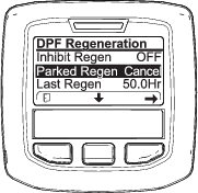
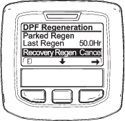
Accessing the DPF Regeneration Menus
Accessing the DPF Regeneration Menus
Time Since Last Regeneration
Access the DPF Regeneration menu, press the center button to scroll down to the LAST REGEN field (Figure 33).
Use the LAST REGEN field to determine how many hours you have run the engine since the last reset, parked, or recovery regeneration.
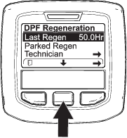
Technician Menu
Important: For operating convenience, you may decide to perform a parked regeneration before the soot load reaches 100%, provided the engine has run more than 50 hours since the last successful reset, parked, or recovery regeneration.
Use the technician menu to view the current state of engine regeneration control and view the reported soot level.
Access the DPF Regeneration menu, press the center button to scroll down to the TECHNICIAN option, and press the right button to select the Technician entry (Figure 34).
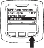
-
Use the DPF operation table to understand the current state of DPF operation (Figure 35).
.
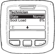
DPF Operation Table
State Description Normal The DPF is in normal-operating mode—passive regeneration. Assist Regen The engine computer is performing an assist regeneration. Reset Stby The engine computer is trying to run a reset regeneration, but 1 of the following conditions prevents regeneration: The regen inhibit setting is set to ON. The exhaust temperature is too low for regeneration. Reset Regen The engine computer is running a reset regeneration. Parked Stby The engine computer is requesting that you run a parked regeneration. Parked Regen You initiated a parked regeneration request and the engine computer is processing the regeneration. Recov. Stby The engine computer is requesting that you run a recovery regeneration. Recov. Regen YTeou initiated a recovery regeneration request and the engine computer is processing the regeneration. -
View the soot load which is measured as the percentage of soot in the DPF (Figure 36); refer to the soot-load table.
Note: The soot load value varies as the machine is operated and DPF regeneration occurs.

Soot-Load Table
Important Soot Load Values Regeneration State 0% to 5% Minimum soot load range 78% The engine computer performs an assist regeneration. 100% The engine computer automatically requests a parked regeneration. 122% The engine computer automatically requests a recovery regeneration.
Passive DPF Regeneration
-
Passive regeneration occurs as part of normal engine operation.
-
While operating the machine, run the engine at full-engine speed and high load when possible to promote DPF regeneration.
Assist DPF Regeneration
-
The engine computer adjusts engine settings to raise the exhaust temperature.
-
While operating the machine, run the engine at full engine speed and high load when possible to promote DPF regeneration.
Reset Regeneration
Caution
The exhaust temperature is hot (approximately 600°C (1,112°F) during DPF regeneration. Hot exhaust gas can harm you or other people.
-
Never operate the engine in an enclosed area.
-
Make sure that there are no flammable materials around the exhaust system.
-
Never touch a hot exhaust system component.
-
Never stand near or around the exhaust pipe of the machine.
-
The high exhaust-temperature icon
displays in the InfoCenter
(Figure 37). -
The engine computer adjusts engine settings to raise the exhaust temperature.
Important: The high exhaust-temperature icon indicates that the exhaust temperature discharged from of your machine may be hotter than during regular operation.
-
While operating the machine, run the engine at full engine speed and high load when possible to promote DPF regeneration.
-
The icon displays in the InfoCenter while the reset regeneration is processing.
-
Whenever possible, do not shut off the engine or reduce engine speed while the reset regeneration is processing.
Important: Whenever possible, allow the machine to complete the reset regeneration process before shutting off the engine.
Periodic Reset Regeneration
If the engine has not completed a successful Reset, Parked, or Recovery regeneration in the previous 100 hours of engine operation, the engine computer will attempt to perform a reset regeneration.
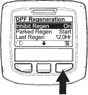
Setting the Inhibit Regen
Reset Regeneration Only

Note: If you set the InfoCenter to inhibit regeneration, the InfoCenter displays ADVISORY #185 (Figure 38) every 15 minutes while the engine requests a reset regeneration.
A reset regeneration produces the elevated engine exhaust. If you are operating the machine around trees, brush, tall grass, or other temperature-sensitive plants or materials, you can use the Inhibit Regen setting to prevent the engine computer from performing a reset regeneration.
Important: When you shut off the engine and start it again, the inhibit regen setting defaults to OFF.

Allowing a Reset Regeneration
The InfoCenter displays the high exhaust-temperature icon when the reset regeneration
is in process.
Note: If INHIBIT REGEN is set to ON, the InfoCenter displays ADVISORY #185 (Figure 41). Press button 3 to set inhibit regeneration setting to OFF and continue with the reset regeneration.
Note: If the engine exhaust temperature is too low, the InfoCenter displays ADVISORY #186 (Figure 42) to inform you to set the engine to full throttle (high idle).

Note: When the reset regeneration completes, the high exhaust-temperature disappears from the InfoCenter
screen.
Parked or Recovery Regeneration
-
When the engine computer requests either a parked regeneration or a recovery regeneration, the regeneration request icon (Figure 43) displays in the InfoCenter.
-
The machine does not automatically perform a parked regeneration or a recovery regeneration, you must run the regeneration through the InfoCenter.
Parked Regeneration Messages

Recovery Regeneration Messages

DPF Status-Limitation
-
If the engine computer requests a recovery regeneration or is processing a recovery regeneration and you scroll down to the PARKED REGEN option, parked regeneration locks and the lock icon (Figure 48) appears in the lower right corner of the InfoCenter.
-
If the engine computer has not requested a recovery regeneration and you scroll down to the RECOVERY REGEN option, the recovery regeneration locks and the lock icon (Figure 49) appears in the lower right corner of the InfoCenter.
Preparing to Perform a Parked or Recovery Regeneration
-
Ensure that the machine has fuel in the tank for the type of regeneration you are performing:
-
Parked Regeneration: Ensure that you have 1/4 tank of fuel before performing the parked regeneration.
-
Recovery Regeneration: Ensure that you have 1/2 tank of fuel before performing the recovery regeneration.
-
-
Move the machine outside to an area away from combustible materials.
-
Park the machine on a level surface.
-
Ensure that the traction control or motion-control levers are in the NEUTRAL position.
-
If applicable, shut off the PTO, and lower the cutting units or accessories.
-
Engage the parking brake.
-
Set the throttle to the low IDLE position.
Performing a Parked or Recovery Regeneration
Caution
The exhaust temperature is hot (approximately 600°C (1,112°F) during DPF regeneration. Hot exhaust gas can harm you or other people.
-
Never operate the engine in an enclosed area.
-
Make sure that there are no flammable materials around the exhaust system.
-
Never touch a hot exhaust system component.
-
Never stand near or around the exhaust pipe of the machine.
Important: The computer of the machine cancels DPF regeneration if you increase the engine speed from low idle or release the parking brake.
-
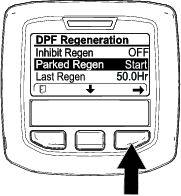
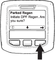
Access the DPF Regeneration menu, press the center button to scroll down to either the PARKED REGEN START option or the RECOVERY REGEN START option (Figure 50), and press the right button to select the start the regeneration (Figure 50).

-
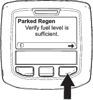
At the VERIFY FUEL LEVEL screen, verify that you have 1/4 tank of fuel if you are performing the parked regeneration or 1/2 tank of fuel if you are performing the recovery regeneration, and press the right button to continue (Figure 51).

-
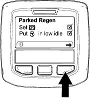
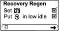
At the DPF checklist screen, verify that the parking brake is engaged and that the engine speed is set to low idle (Figure 52).
-
At the INITIATE DPF REGEN screen, press the right button to continue (Figure 53).

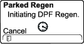
-
The InfoCenter displays the INITIATING DPF REGEN message (Figure 54).

-
The InfoCenter displays the time to complete message (Figure 55).

-
The engine computer checks the engine state and fault information. The InfoCenter may display the following messages found in the table that follows:
Check Message and Corrective Action Table

Corrective Action: Exit the regeneration menu and run the machine until the time since last regeneration is greater than 50 hours; refer to Time Since Last Regeneration. 

Corrective Action: Troubleshoot the engine fault and retry DPF regeneration. 

Corrective Action: Start and run the engine. 

Corrective Action: Run the engine to warm the coolant temperature to 60°C (140°F). 

Corrective Action: Change the engine speed to low idle. 

Corrective Action: Troubleshoot the engine computer condition and retry DPF regeneration. -
The InfoCenter displays the home screen and the regeneration acknowledge icon (Figure 56) appears in the lower right corner of the screen as the regeneration processes.
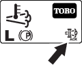
Note: While the DPF regeneration runs, the InfoCenter displays the high exhaust-temperature icon
. -
When the engine computer completes a parked or recovery regeneration, the InfoCenter displays ADVISORY #183 (Figure 57). Press the left button to exit to the home screen.
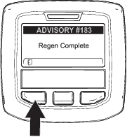
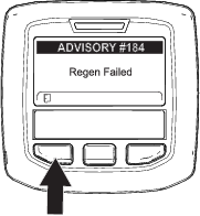
Note: If the regeneration fails to complete, the InfoCenter displays Advisory #184 (Figure 57). Press the left button to exit to the home screen.
Canceling a Parked or Recovery Regeneration
Use the Parked Regen Cancel or Recovery Regen Cancel setting to cancel a running parked or recovery regeneration process.
Operating Tips
Fast Throttle Setting/Ground Speed
To maintain enough power for the machine and deck while mowing, operate the engine at the FAST throttle position and adjust your ground speed for conditions. Decrease the ground speed as the load on the cutting blades increase; increase the ground speed as the load on the blades decrease.
Alternating the Mowing Direction
Alternate your mowing direction to avoid making ruts in the turf, which can appear over time. This also helps to disperse clippings, which enhances decomposition and fertilization.
Cutting Speed
To improve cut quality, use a slower ground speed in certain conditions.
Avoiding a Low Cut
If the machine cutting width is wider than the machine that you previously used, raise the cutting height to ensure that uneven turf is not cut too short.
Select the Proper Height-of-Cut Setting to Suit Conditions
Remove approximately 25 mm (1 inch) or no more than 1/3 of the grass blade when cutting. In exceptionally lush and dense grass, you may need to slow down the forward speed and/or raise the height-of-cut to the next higher setting.
Important: If you are cutting more than 1/3 of the grass blade, or are mowing in sparse long grass or dry conditions, use the flat sail of the blades to reduce air-borne chaff, debris, and strain on the deck-drive components.
Cutting Long Grass
If you allow the grass to grow slightly longer than normal, or if the grass contains a high degree of moisture, raise the cutting height to a higher setting and cut the grass at this setting. Then cut the grass again using the lower, normal setting.
Keeping the Mower Clean
Clean clippings and dirt from the underside of the mower after each use. If grass and dirt build up inside the mower, cutting quality eventually becomes unsatisfactory.
To reduce the risk of fire hazard, keep the engine, muffler, battery compartment, parking brake, cutting units, and fuel storage compartment free of grass, leaves, or excessive grease. Clean up any spilled oil or fuel.
Maintaining the Blades
-
Maintain sharp blades throughout the cutting season. Sharp blades create a clean cut without tearing or shredding the grass blades. Tearing and shredding causes grass to turn brown at the edges, which slows growth and increases the chance of disease.
-
Check the blades daily for sharpness and for any wear or damage. Sharpen the blades as necessary.
-
If a blade is damaged or worn, replace it immediately with a genuine Toro replacement blade. Refer to the cutting unit Operator’s Manual for instructions to replace the blade.
After Operation
General Safety
-
Shut off the engine, remove the key (if equipped), and wait for all movement to stop before you leave the operator’s position, Allow the machine to cool before adjusting, servicing, cleaning, or storing it.
-
Clean grass and debris from the cutting units, mufflers, and engine compartment to help prevent fires. Clean up oil or fuel spills.
-
If the cutting units are in the transport position, use the positive mechanical lock (if available) before you leave the machine unattended.
-
Allow the engine to cool before storing the machine in any enclosure.
-
Remove the key and shut off the fuel (if equipped) before storing or hauling the machine.
-
Never store the machine or fuel container where there is an open flame, spark, or pilot light, such as on a water heater or on other appliances.
-
Maintain and clean the seat belt(s) as necessary
Pushing the Machine
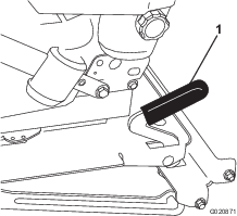
In an emergency, you can move the machine a very short distance by actuating the bypass valves in the hydraulic pump and pushing the machine.
Important: Always push the machine by hand and never a long distance. Never tow the machine, because damage to the hydraulic system may occur.
Important: The bypass valves must be open whenever you push or tow the machine. Close the valves once you have pushed or towed the machine to the desired location.
-
Lift the seat; refer to Unlatching the Seat
-
Locate the bypass valves (Figure 61) and rotate each bypass valve counterclockwise 1 turn.
Note: This allows hydraulic fluid to bypass the pump, enabling the wheels to turn.
Important: Do not rotate the bypass valves more than 1 turn. This prevents valves from coming out of the body and causing fluid to run out.
-
Ensure that the parking brake is disengaged and push the machine to the desired location.
-
Close the valves by rotating each valve 1 clockwise turn (Figure 61).
Note: Do not overtighten the valves.
-
Torque the valves to approximately 8 N∙m (71 in-lb).
Important: Ensure that the bypass valves are closed before you start the engine. Running the engine with open bypass valves causes the transmission to overheat.
Hauling the Machine
Use a heavy-duty trailer or truck to haul the machine. Ensure that the trailer or truck has all the necessary brakes, lighting, and marking as required by law. Please carefully read all the safety instructions. Knowing this information could help you, your family, pets, or bystanders avoid injury.
Warning
Driving on the street or roadway without turn signals, lights, reflective markings, or a slow-moving-vehicle emblem is dangerous and can lead to accidents causing personal injury.
Do not drive the machine on a public street or roadway.
-
If you are using a trailer, connect it to the towing vehicle, and connect the safety chains.
-
If applicable, connect the trailer brakes.
-
Load the machine onto the trailer or truck; refer to Loading the Machine.
-
Shut off the engine, remove the key, engage the parking brake, and close the fuel valve.
-
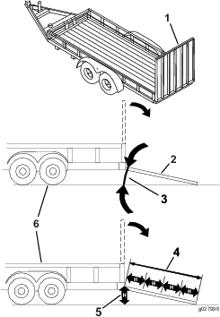
Use the tie-down loops on the machine to securely fasten it to the trailer or truck with straps, chains, cable, or ropes (Figure 62).
Loading the Machine
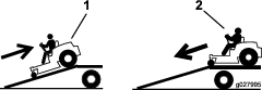
Use extreme caution when loading or unloading machines onto a trailer or a truck. Use a full-width ramp that is wider than the machine for this procedure. Drive the machine up ramps in reverse and drive it down ramps in a forward direction (Figure 63).
Important: Do not use narrow individual ramps for each side of the machine.
Warning
Loading the machine onto a trailer or truck increases the possibility of tipover and could cause serious injury or death.
-
Use extreme caution when operating a machine on a ramp.
-
When loading or unloading the machine, use the seat belt and ensure that the roll bar is in the raised position. Ensure that the roll bar can clear the top of an enclosed trailer.
-
Use only a full-width ramp; do not use individual ramps for each side of the machine.
-
Do not exceed a 15° angle between the ramp and the ground, or between the ramp and the trailer or truck.
-
Ensure that the ramp length is at least 4 times as long as the height of the trailer or truck bed to the ground. This ensures that the ramp angle does not exceed 15° on flat ground.
-
Drive the machine up ramps in reverse and drive it down ramps in a forward direction.
-
While driving the machine on a ramp, avoid sudden acceleration or deceleration, as this could cause a loss of control or a tipover situation.
Maintenance
Note: Determine the left and right sides of the machine from the normal operating position.
Important: Refer to your engine owner’s manual for additional maintenance procedures.
Note: Download a free copy of the electrical or hydraulic schematic by visiting www.Toro.com and searching for your machine from the Manuals link on the home page.
Maintenance Safety
-
Before you leave the operator’s position, do the following:
-
Park the machine on a level surface.
-
Disengage the power takeoff and lower the attachments.
-
Engage the parking brake.
-
Shut off the engine and remove the key.
-
Wait for all movement to stop.
-
-
If you leave the key in the switch, someone could accidently start the engine and seriously injure you or other bystanders. Remove the key from the switch before you perform any maintenance.
-
Allow machine components to cool before performing maintenance.
-
If the cutting units are in the transport position, use the positive mechanical lock (if equipped) before you leave the machine unattended.
-
If possible, do not perform maintenance while the engine is running. Keep away from moving parts.
-
Support the machine with jack stands whenever you work under the machine.
-
Carefully release pressure from components with stored energy.
-
Keep all parts of the machine in good working condition and all hardware tightened, especially blade-attachment hardware.
-
Replace all worn or damaged decals.
-
To ensure safe, optimal performance of the machine, use only genuine Toro replacement parts. Replacement parts made by other manufacturers could be dangerous, and such use could void the product warranty.
Recommended Maintenance Schedule(s)
| Maintenance Service Interval | Maintenance Procedure |
|---|---|
| After the first 10 hours |
|
| After the first 50 hours |
|
| After the first 200 hours |
|
| Before each use or daily |
|
| Every 50 hours |
|
| Every 100 hours |
|
| Every 150 hours |
|
| Every 200 hours |
|
| Every 250 hours |
|
| Every 400 hours |
|
| Every 800 hours |
|
| Every 1,500 hours |
|
| Every 3,000 hours |
|
| Before storage |
|
| Every 2 years |
|
Lubrication
Greasing the Bearings and Bushings
| Maintenance Service Interval | Maintenance Procedure |
|---|---|
| Every 50 hours |
|
The machine has grease fittings that you must lubricate regularly with No. 2 lithium grease. Lubricate more often in dirty or dusty conditions because dirt can get into the bearings and bushings and cause accelerated wear.
-
Wipe the grease fittings clean so that foreign matter cannot be forced into the bearing or bushing.
-
Pump grease into the fittings.
-
Wipe off excess grease.
Note: Improper wash-down procedures can negatively affect bearing life. Do not wash down the machine when it is still hot and avoid directing high-pressure or high-volume spray at the bearings or seals.
Servicing the Cutting-Unit Gearbox Lubricant
The gear box is designed to operate with SAE EP90W gear lube. Although the gearbox comes from the factory with lubricant, check the level of the lubricant in the cutting unit before operating it and as recommended in the Daily Maintenance Checklist.
Checking the Cutting-Unit Gearbox Lubricant
| Maintenance Service Interval | Maintenance Procedure |
|---|---|
| Every 150 hours |
|
-
Position the machine and cutting unit on a level surface.
-
Lower the cutting unit to the 2.5 cm (1 inch) height of cut.
-
Disengage the PTO, move the motion-control levers to the NEUTRAL-LOCK position, and engage the parking brake.
-
Move the throttle lever to the SLOW position, shut off the engine, remove the key, and wait for all moving parts to stop before leaving the operating position.
-
Lift the footrest, exposing the top of the cutting unit.
-
Remove the dipstick/fill plug from the top of the gearbox and make sure that the lubricant is between the marks on the dipstick (Figure 65).
-
If the lubricant level is low, add enough lubricant until the level is between the marks on the dipstick.
Important: Do not overfill the gearbox; overfilling the gearbox may damage it.
Changing the Cutting-Unit Gearbox Lubricant
| Maintenance Service Interval | Maintenance Procedure |
|---|---|
| After the first 50 hours |
|
| Every 400 hours |
|
-
Position the machine and cutting unit on a level surface.
-
Lower the cutting unit to the 2.5 cm (1 inch) height of cut.
-
Disengage the PTO, move the motion-control levers to the NEUTRAL-LOCK position, and engage the parking brake.
-
Move the throttle lever to the SLOW position, shut off the engine, remove the key, and wait for all moving parts to stop before leaving the operating position.
-
Lift the footrest, exposing the top of the cutting unit.
-
Remove the dipstick/fill plug from the top of the gearbox (Figure 65).
-
Place a funnel and drain pan under the drain plug located under the front of the gearbox and remove the plug, draining the lubricant into the pan.
-
Replace the drain plug.
-
Add enough lubricant, approximately 283 ml (12 fl oz), until the level is between the marks on the dipstick.
Important: Do not overfill the gearbox; overfilling the gearbox may damage it.
Engine Maintenance
Engine Safety
-
Shut off the engine and remove the key before checking the oil or adding oil to the crankcase.
-
Do not change the governor speed or overspeed the engine.
Checking the Air Cleaner
| Maintenance Service Interval | Maintenance Procedure |
|---|---|
| Every 400 hours |
|
-
Check the air-cleaner body for damage, which could possibly cause an air leak. Replace a damaged air-cleaner body.
-
Check the air-intake system for leaks, damage, or loose hose clamps.
-
Service the air-cleaner filter (Figure 66).
Important: Do not over-service the air filter.
-
Ensure that the cover is seated correctly and seals with the air-cleaner body.
Servicing the Air Cleaner
| Maintenance Service Interval | Maintenance Procedure |
|---|---|
| Every 400 hours |
|
Note: If the foam gasket in the cover is damaged, replace it.
Important: Avoid using high-pressure air, which could force dirt through the filter into the intake tract.
Important: Do not clean the used filter to avoid damage to the filter media.
Important: Do not use a damaged filter.
Important: Do not apply pressure to the flexible center of the filter.
Servicing the Engine Oil
Oil Specification
Use high-quality, low-ash engine oil that meets or exceeds the following specifications:
-
API service category CJ-4 or higher
-
ACEA service category E6
-
JASO service category DH-2
Important: Using engine oil other than API CJ-4 or higher, ACEA E6, or JASO DH-2 may cause the diesel particulate filter to plug or cause engine damage.
Use the following engine oil viscosity grade:
-
Preferred oil: SAE 15W-40 (above 0°F)
-
Alternate oil: SAE 10W-30 or 5W-30 (all temperatures)
Toro Premium Engine Oil is available from your Authorized Toro Distributor in either 15W-40 or 10W-30 viscosity grades. See the parts catalog for part numbers.
Checking the Engine-Oil Level
| Maintenance Service Interval | Maintenance Procedure |
|---|---|
| Before each use or daily |
|
The engine is shipped with oil in the crankcase; however, the oil level must be checked before and after the engine is first started.
Important: Check the engine oil daily. If the engine-oil level is above the Full mark on the dipstick, the engine oil may be diluted with fuel;If the engine oil level is above the Full mark, change the engine oil.
The best time to check the engine oil is when the engine is cool before it has been started for the day. If it has already been run, allow the oil to drain back down to the sump for at least 10 minutes before checking. If the oil level is at or below the Add mark on the dipstick, add oil to bring the oil level to the Full mark. Do not overfill the engine with oil.
Important: Keep the engine oil level between the upper and lower limits on the dipstick; the engine may fail if you run it with too much or too little oil.
-
Park the machine on a level surface.
-
Unlock the hood latches and open the hood.
-
Remove the dipstick, wipe it clean, install the dipstick into the tube, and pull it out again.
The oil level should be in the safe range (Figure 68).
-
If the oil is below the safe range, remove the fill cap (Figure 68) and add oil until the level reaches the Full mark.
Important: Do not overfill the engine with oil.
Note: When using different oil, drain all old oil from the crankcase before adding new oil.
-
Install the oil-fill cap and dipstick.
-
Close the hood and secure it with the latches.
Crankcase Oil Capacity
5.2 liters (5.5 qt) with the filter.
Changing the Engine Oil and Filter
| Maintenance Service Interval | Maintenance Procedure |
|---|---|
| Every 250 hours |
|
-
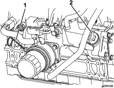
Remove the oil-drain plug (Figure 69) and let the oil flow into a drain pan. When all the oil is drained, install the drain plug.
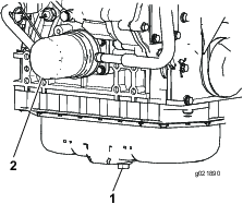
-
Remove the oil filter (Figure 69). Apply a light coat of clean oil to the new filter seal before screwing it on. Do not overtighten.
-
Add oil to the crankcase; refer to Checking the Engine-Oil Level.
Servicing the Diesel-Oxidation Catalyst (DOC) and the Soot Filter
| Maintenance Service Interval | Maintenance Procedure |
|---|---|
| Every 3,000 hours |
|
If engine faults , , or in the InfoCenter (Figure 70) display in the InfoCenter, clean the soot filter using the steps that follow:
-
Refer to the Engine section in the Service Manual for information on disassembling and assembling the diesel-oxidation catalyst and the soot filter of the DPF.
-
Refer to your authorized Toro distributor for diesel-oxidation catalyst and the soot filter replacement parts or service.
-
Contact your authorized Toro distributor to have them reset the engine ECU after you install a clean DPF.
Fuel System Maintenance
Note: Refer to Fuel Specification for proper fuel recommendations.
Danger
Under certain conditions, diesel fuel and fuel vapors are highly flammable and explosive. A fire or explosion from fuel can burn you and others and can cause property damage.
-
Use a funnel and fill the fuel tank outdoors, in an open area, when the engine is off and is cold. Wipe up any fuel that spills.
-
Do not fill the fuel tank completely full. Add fuel to the fuel tank until the level is to the bottom of the filler neck.
-
Never smoke when handling fuel, and stay away from an open flame or where fuel fumes may be ignited by a spark.
-
Store fuel in a clean, safety-approved container and keep the cap in place.
Servicing the Engine Fuel Filter
| Maintenance Service Interval | Maintenance Procedure |
|---|---|
| Every 400 hours |
|
-
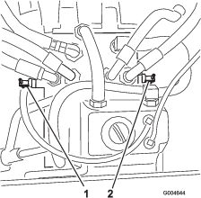
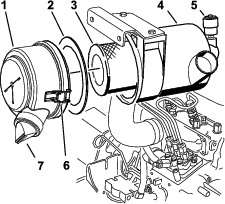
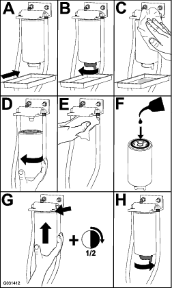
Clean the area around the fuel filter head (Figure 71).
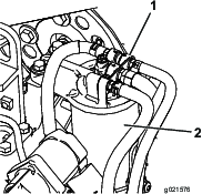
-
Remove the filter and clean the filter head mounting surface (Figure 71).
-
Lubricate the filter gasket with clean lubricating engine oil. Refer to the engine owner's manual, included with the machine, for additional information.
-
Install the dry filter canister, by hand, until the gasket contacts the filter head, then rotate it an additional 1/2 turn.
-
Start the engine and check for fuel leaks around the filter head.
Servicing the Water Separator
| Maintenance Service Interval | Maintenance Procedure |
|---|---|
| Every 400 hours |
|
Draining the Fuel Tank
| Maintenance Service Interval | Maintenance Procedure |
|---|---|
| Every 800 hours |
|
| Before storage |
|
In addition to the listed service interval, drain and clean the tank if the fuel system becomes contaminated or if you are storing the machine for an extended period. Use clean fuel to flush out the tank.
Inspecting the Fuel Lines and Connections
| Maintenance Service Interval | Maintenance Procedure |
|---|---|
| Every 400 hours |
|
Inspect the fuel lines for deterioration, damage, or loose connections.
Electrical System Maintenance
Electrical System Safety
-
Disconnect the battery before repairing the machine. Disconnect the negative terminal first and the positive last. Connect the positive terminal first and the negative last.
-
Charge the battery in an open, well-ventilated area, away from sparks and flames. Unplug the charger before connecting or disconnecting the battery. Wear protective clothing and use insulated tools.
Servicing the Battery
| Maintenance Service Interval | Maintenance Procedure |
|---|---|
| Every 50 hours |
|
Keep the top of the battery clean. If you store the machine in a location where temperatures are extremely high, the battery will run down more rapidly than if the machine is stored in a location where the temperature is cool.
Keep the top of the battery clean by washing it periodically with a brush dipped in ammonia or bicarbonate of soda solution. Flush the top surface with water after cleaning it. Do not remove the fill caps while cleaning the battery.
The battery cables must be tight on the terminals to provide good electrical contact.
If corrosion occurs at the terminals, disconnect the cables, negative (-) cable first, and scrape the clamps and terminals separately. Connect the cables, positive (+) cable first, and coat the terminals with petroleum jelly.
Warning
Battery terminals or metal tools could short against metal machine components causing sparks. Sparks can cause the battery gasses to explode, resulting in personal injury.
-
When removing or installing the battery, do not allow the battery terminals to touch any metal parts of the machine.
-
Do not allow metal tools to short between the battery terminals and metal parts of the machine.
Warning
Incorrect battery cable routing could damage the machine and cables causing sparks. Sparks can cause the battery gasses to explode, resulting in personal injury.
-
Always disconnect the negative (black) battery cable before disconnecting the positive (red) cable.
-
Always connect the positive (red) battery cable before connecting the negative (black) cable.
Storing the Battery
If you are storing the machine more than 30 days, remove the battery and charge it fully. Either store it on a shelf or on the machine. Do not connect the cables if you store it on the machine. Store the battery in a cool environment to prevent the battery from discharging rapidly. To prevent the battery from freezing, make sure it is fully charged. The specific gravity of a fully charged battery is 1.265 to 1.299.
Checking the Fuses
The fuses are located under the control panel. Access them through the side panel cover (Figure 73). To open the side panel cover, release the 2 latches and pull out on it.
If the machine stops or has other electrical system issues, check the fuses. Grasp each fuse in turn and remove them 1 at a time, checking if any are blown.
Important: If you need to replace a fuse, always use the same type and amperage-rated fuse as the one you are replacing, otherwise you could damage the electrical system. Refer to the decal next to the fuses for a diagram of each fuse and its amperage (Figure 74).
Note: If a fuse blows frequently, you may have a short in the electrical system and should have it serviced by a qualified service technician.
Drive System Maintenance
Checking the Tire Pressure
| Maintenance Service Interval | Maintenance Procedure |
|---|---|
| Every 50 hours |
|
Maintain the air pressure in the front and rear tires (Figure 75). The correct air pressure is 124 kPa (15 psi) in the rear tires and 103 kPa (25 psi) in the caster wheels. Uneven tire pressure can cause an uneven cut.
Note: Check the tires when they are cold to get the most accurate pressure reading.
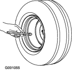
Replacing the Caster Wheels and Bearings
-
Obtain a new caster-wheel assembly, cone bearings, and bearing seals from your Authorized Toro Distributor.
-
Remove the locknut from the bolt (Figure 76).
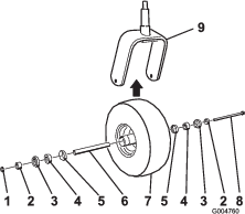
-
Grasp the caster wheel and slide the bolt out of the fork or pivot arm.
-
Discard the old caster wheel and bearings.
-
Assemble the caster wheel by pushing the cone bearings and seals, packed with grease, into the wheel hub, positioned as shown in Figure 76.
-
Slide the spacer into the wheel hub through the bearings, captivating the spacer inside the wheel hub with 2 bearing spacers.
Important: Ensure that the seal lips are not folded inward.
-
Install the caster-wheel assembly between the castor fork and secure it in place with the bolt and locknut.
-
Tighten the locknut until the wheel no longer spins freely, then back it off just until the wheel spins freely.
-
Attach a grease gun to the grease fitting on the caster wheel and fill it with No. 2 lithium grease.
Cooling System Maintenance
Cooling System Safety
-
Swallowing engine coolant can cause poisoning; keep out of reach from children and pets.
-
Discharge of hot, pressurized coolant or touching a hot radiator and surrounding parts can cause severe burns.
-
Always allow the engine to cool at least 15 minutes before removing the radiator cap.
-
Use a rag when opening the radiator cap, and open the cap slowly to allow steam to escape.
-
-
Do not operate the machine without the covers in place.
-
Keep your fingers, hands, and clothing clear of rotating fan and drive belt.
Coolant Specification
The coolant reservoir is filled at the factory with a 50/50 solution of water and ethylene glycol base extended-life coolant.
Important: Use only commercially available coolants that meet the specifications listed in the Extended Life Coolant Standards Table.Do not use conventional (green) inorganic-acid technology (IAT) coolant in your machine. Do not mix conventional coolant with extended-life coolant.
|
Ethylene-Glycol Coolant Type |
Corrosion Inhibitor Type |
|
Extended-life antifreeze |
Organic-acid technology (OAT) |
|
Important: Do not rely on the color of the coolant to identify the difference between conventional (green) inorganic-acid technology (IAT) coolant and extended-life coolant.Coolant manufacturers may dye extended-life coolant in one of the following colors: red, pink, orange, yellow, blue, teal, violet, and green. Use coolant that meets the specifications in the Extended Life Coolant Standards Table. |
|
|
ATSM International |
SAE International |
|
D3306 and D4985 |
J1034, J814, and 1941 |
Important: Coolant concentration should be a 50/50 mixture of coolant to water.
-
Preferred: When mixing coolant from a concentrate, mix it with distilled water.
-
Preferred option: If distilled water is not available, use a pre-mix coolant instead of a concentrate.
-
Minimum requirement: If distilled water and pre-mix coolant are not available, mix concentrated coolant with clean drinkable water.
Checking the Cooling System
| Maintenance Service Interval | Maintenance Procedure |
|---|---|
| Before each use or daily |
|
The cooling system is filled with a 50/50 solution of water and permanent ethylene glycol anti freeze. The capacity of the cooling system is 7.5 L (6 US qt).
-
Check the level of the coolant in the expansion tank (Figure 77).
Note: The coolant level should be between the marks on the side of the tank.
-
If coolant level is low, remove the expansion-tank cap and replenish the system.
Important: Do not overfill.
-
Install the expansion-tank cap.
Cleaning the Radiator
| Maintenance Service Interval | Maintenance Procedure |
|---|---|
| Before each use or daily |
|
| Every 200 hours |
|
| Every 1,500 hours |
|
| Every 2 years |
|
Clean the radiator to prevent the engine from overheating.
Note: If the cutting unit or engine shuts off due to overheating, check the radiator for excessive buildup of debris.
Clean the radiator as follows:
-
Open the hood.
-
Working from the fan side of the radiator, blow out debris with low pressure (345 kPa or 50 psi), compressed air. Repeat from the front of the radiator and the other fan side.
Important: Do not use water.
-
After you thoroughly clean the radiator, clean out debris that may have collected in the channel at the radiator base.
-
Close the hood.
Brake Maintenance
Adjusting the Parking-Brake Interlock Switch
-
Stop the machine, move the motion-control levers to the NEUTRAL-LOCK position, engage the parking brake, and remove the ignition key.
-
Remove the bolts securing the front panel and remove the panel (Figure 78).
-
Loosen the 2 jam nuts securing the parking-brake interlock switch to the mounting bracket.
-
Move the switch up or down on the bracket until the distance between the brake-shaft sensor and the switch plunger is 4 mm (5/32 inch) as shown in Figure 79.
Note: Make sure that the brake-shaft sensor does not contact the switch plunger.
-
Secure the switch jam nuts.
-
Test the adjustment as follows:
-
Ensure that the parking brake is engaged and you are not sitting on the seat, then start the engine.
-
Move the control levers out of the NEUTRAL-LOCK position.
Note: The engine should shut off. If not, check the adjustment that you made to the switch.
-
-
Install the front panel.
Belt Maintenance
Checking the Alternator-Belt Tension
| Maintenance Service Interval | Maintenance Procedure |
|---|---|
| Every 100 hours |
|
-
Apply 44 N (10 lb) of force to the alternator belt, midway between the pulleys.
-
If the deflection is not 10 mm (3/8 inch), loosen the alternator mounting bolts (Figure 80).
-
Increase or decrease the alternator-belt tension.
-
Tighten the mounting bolts.
-
Check the deflection of the belt again to ensure that the tension is correct.
Controls System Maintenance
Adjusting the Control-Lever Neutral-Interlock Switch
-
Stop the machine, move the motion-control levers to the NEUTRAL-LOCK position, engage the parking brake, and remove the ignition key.
-
Remove the bolts securing the front panel and remove the panel (Figure 81).
-
Loosen the 2 screws securing the interlock switch (Figure 82).
-
Holding the control lever against the frame, move the switch toward the lever until the distance between the lever and switch body is 0.4 to 1 mm (0.015 to 0.045 inch) as shown in Figure 82.
-
Secure the switch.
-
Repeat steps 3 to 5 for the other lever.
-
Install the front panel.
Adjusting the Control-Lever Neutral Return
If the motion-control levers do not align with the neutral slots when released from the REVERSE position, adjustment is required. Adjust each lever, spring, and rod separately.
-
Disengage the PTO, move the control lever to the NEUTRAL-LOCK position, and engage the parking brake.
-
Move the throttle lever to the SLOW position, shut off the engine, remove the key, and wait for all moving parts to stop before leaving the operating position.
-
Remove the bolts securing the front panel and remove the panel (Figure 83).
-
Move the control lever to the NEUTRAL position but not locked (Figure 85).
-
Pull the lever back until the clevis pin (on an arm above the pivot shaft) contacts the end of the slot (just beginning to put pressure on the spring) as shown in Figure 84.
-
Check where the control lever is relative to notch in the console (Figure 85).
Note: The control lever should be centered, allowing lever to pivot outward to the NEUTRAL-LOCK position.
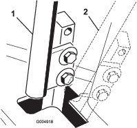
-
If adjustment is needed, loosen the nut and jam nut against the yoke (Figure 84).
-
Applying slight rearward pressure on the motion-control lever, turn the head of the adjustment bolt in the appropriate direction until the control lever is centered in the NEUTRAL-LOCK position (Figure 84).
Note: Rearward pressure on the lever keeps the pin at the end of the slot and allow the adjustment bolt to move the lever to the appropriate position.
-
Tighten the nut and jam nut (Figure 84).
-
Repeat steps 4 through 9 for the other control lever.
-
Install the front panel.
Adjusting the Traction Drive for Neutral
Make this adjustment with the drive wheels turning.
Danger
Mechanical or hydraulic jacks may fail to support the machine and cause a serious injury.
-
Use jack stands when supporting the machine.
-
Do not use hydraulic jacks.
Warning
The engine must be running to perform this adjustment. Contact with moving parts or hot surfaces may cause personal injury.
Keep hands, feet, face, clothing, and other body parts away from rotating parts, muffler, and other hot surfaces.
-
Raise the frame onto stable jack stands so that the drive wheels can rotate freely.
-
Slide the seat forward, unlatch it, and swing it up and forward.
-
Disconnect the electrical connector from the seat safety switch.
-
Temporarily install a jumper wire across the terminals in the wire harness connector.
-
Start the engine, ensure that the throttle lever is midway between the FAST and SLOW positions, and release the parking brake.
Note: The motion-control levers must be in the NEUTRAL-LOCK position while you make any adjustments.
-
Adjust the pump rod length on one side by rotating the hex shaft, in the appropriate direction, until the corresponding wheel is still or slightly creeping in reverse (Figure 86).
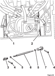
-
Move the motion-control lever forward and reverse, then back to neutral.
Note: The wheel must stop turning or slightly creep in reverse.
-
Move the throttle lever to the FAST position.
Note: Make sure that the wheel remains stopped or slightly creeps in reverse; adjust it if necessary.
-
Repeat steps 6 through 8 for the other side of the machine.
-
Tighten the jam nuts at the ball joints (Figure 84).
-
Move the throttle lever to the SLOW position and shut off the engine.
-
Remove the jumper wire from the wire harness connector and plug the connector into the seat switch.
Warning
The electrical system does not perform proper safety shutoff with the jumper wire installed.
-
Remove the jumper wire from the wire harness connector and plug the connector into the seat switch when you complete adjustment.
-
Never operate the machine with the jumper installed and the seat switch bypassed.
-
-
Lower the seat into position.
-
Remove the jack stands.
Adjusting the Maximum Ground Speed
-
Disengage the PTO, move the motion-control levers to the NEUTRAL-LOCK position, and engage the parking brake.
-
Move the throttle lever to the SLOW position, shut off the engine, remove the key, and wait for all moving parts to stop before leaving the operating position.
-
Remove the bolts securing the front panel and remove the panel (Figure 87).
-
Loosen the jam nut on the stop bolt for a control lever (Figure 88).
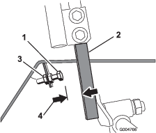
-
Thread the stop bolt all the way in (away from the control lever).
-
Push the control lever all the way forward until it stops and hold it there.
-
Thread the stop bolt out (toward the control lever) until there is a gap of 1.5 mm (0.060 inch) between the head of the stop bolt and the control lever.
Note: If you want to reduce the maximum machine speed, back each stop bolt out an equal amount toward the control lever until you reach the desired maximum speed. You may need to test your adjustment several times.
-
Tighten the jam nut to secure the stop bolt in place.
-
Repeat steps 4 through 8 for the other control lever.
-
Install the front panel.
-
Ensure that the machine drives straight and does not turn when both control levers are pushed all the way forward.
Note: If the machine turns, the stop bolts are not evenly set and you need to adjust them further.
Adjusting the Tracking
-
Disengage the PTO, move the motion-control levers to the NEUTRAL-LOCK position, and engage the parking brake.
-
Move the throttle lever to the SLOW position, shut off the engine, remove the key, and wait for all moving parts to stop before leaving the operating position.
-
Loosen the bolts securing the control levers (Figure 89).
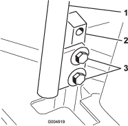
-
Have someone push the control-lever posts (not the control levers) all the way forward into the maximum-speed position and hold them there.
-
Adjust the control levers so that they line up and tighten the bolts, securing the levers to the posts (Figure 90).

Hydraulic System Maintenance
Hydraulic Fluid Capacity
The reservoir is approximately 4.7 liters (5 quarts).
Hydraulic Fluid Specification
The reservoir is filled at the factory with high-quality tractor transmission/hydraulic fluid. The recommended replacement fluid is as follows:
Toro Premium Transmission/Hydraulic Tractor Fluid (Available in 19 L (5 gallon) pails or 208 L (55 gallon) drums. See the Parts Catalog or your Toro Distributor for part numbers).
Alternate fluids: If the Toro fluid is not available, Mobil® 424 hydraulic fluid may be used.
Note: Toro will not assume responsibility for damage caused by improper substitutions.
Many hydraulic fluids are almost colorless, making it difficult to spot leaks. A red dye additive for the hydraulic system oil is available in 20 ml (2/3 fl oz) bottles. One bottle is sufficient for 15 to 22 L (4 to 6 US gallons) of hydraulic fluid. Order Part No. 44-2500 from your authorized Toro distributor.
Hydraulic System Safety
-
Seek immediate medical attention if fluid is injected into skin. Injected fluid must be surgically removed within a few hours by a doctor.
-
Ensure that all hydraulic-fluid hoses and lines are in good condition and all hydraulic connections and fittings are tight before applying pressure to the hydraulic system.
-
Keep your body and hands away from pinhole leaks or nozzles that eject high-pressure hydraulic fluid.
-
Use cardboard or paper to find hydraulic leaks.
-
Safely relieve all pressure in the hydraulic system before performing any work on the hydraulic system.
Checking the Hydraulic System
| Maintenance Service Interval | Maintenance Procedure |
|---|---|
| Before each use or daily |
|
Check the level of the hydraulic fluid before you first start the engine and daily thereafter.
-
Position the machine on a level surface.
-
Move the motion-control levers to the NEUTRAL-LOCK position and start the engine.
Note: Run the engine at the lowest possible rpm to purge the system of air.
Important: Do not engage the PTO.
-
Raise the deck to extend the lift cylinders, shut off the engine, and remove the key.
-
Raise the seat to access the hydraulic fluid tank.
-
Remove the hydraulic fill cap from the filler neck (Figure 91).
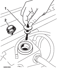
-
Remove the dipstick and wipe it with a clean rag (Figure 91).
-
Place the dipstick into the filler neck; then remove it and check the level of fluid (Figure 91).
Note: If the level is not within the notched area of the dipstick, add enough high-quality hydraulic fluid to raise the level to within the notched area.
Important: Do not overfill.
-
Replace the dipstick and thread the fill cap finger-tight onto the filler neck.
-
Check all hoses and fittings for leaks.
Changing the Hydraulic Fluid and Filter
| Maintenance Service Interval | Maintenance Procedure |
|---|---|
| After the first 200 hours |
|
| Every 800 hours |
|
-
Disengage the PTO, move the motion-control levers to the NEUTRAL-LOCK position, and engage the parking brake.
-
Move the throttle lever to the SLOW position, shut off the engine, remove the key, and wait for all moving parts to stop before leaving the operating position.
-
Place a large pan under the hydraulic reservoir and transmission case and remove the plugs, draining all of the hydraulic fluid (Figure 92).
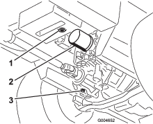
-
Clean the area around the hydraulic fluid filter and remove the filter (Figure 92).
-
Immediately install a new hydraulic fluid filter.
-
Install the hydraulic-reservoir and transmission-case drain plugs.
-
Fill the reservoir to the proper level (approximately 5.7 L or 6 US qt); refer to Checking the Hydraulic System.
-
Start the engine and check for oil leaks. Allow the engine to run for about 5 minutes, then shut it off.
-
After 2 minutes, check the level of the hydraulic fluid; refer to Checking the Hydraulic System.
Cleaning
Cleaning Under the Cutting Unit
| Maintenance Service Interval | Maintenance Procedure |
|---|---|
| Before each use or daily |
|
-
Disengage the PTO, move the motion-control levers to the NEUTRAL-LOCK position, and engage the parking brake.
-
Move the throttle lever to the SLOW position, shut off the engine, remove the key, and wait for all moving parts to stop before leaving the operating position.
-
Raise the cutting unit to the transport position.
-
Raise the front of the machine using jack stands.
-
Thoroughly clean the underside of the cutting unit with water.
Waste Disposal
Engine oil, batteries, hydraulic fluid, and engine coolant are pollutants. Dispose of these according to your state and local regulations.
Storage
Storage Safety
-
Shut off the engine, remove the key, and wait for all movement to stop before you leave the operator’s position. Allow the machine to cool before adjusting, servicing, cleaning, or storing it.
-
Do not store the machine or fuel container where there is an open flame, spark, or pilot light, such as on a water heater or other appliance.
Preparing the Machine for Storage
Important: Do not use brackish or reclaimed water to clean the machine.
-
Remove the key from the ignition switch and store it in a memorable place.
-
Thoroughly clean the machine, deck, and engine, paying special attention to these areas:
-
Radiator and radiator screen
-
Underneath the deck
-
Under the deck belt covers
-
Counterbalance springs
-
PTO-shaft assembly
-
All grease fittings and pivot points
-
Inside the control box
-
Beneath the seat plate and top of the transmission
-
-
Check and adjust front and rear tire pressure; refer to Checking the Tire Pressure.
-
Remove, sharpen, and balance the mower blades. Install the blades and torque the blade fasteners to 115 to 149 N∙m (85 to 110 ft-lb).
-
Check all fasteners for looseness and tighten them as necessary. Torque the 6 bolts securing the mower deck frame to the traction unit (Figure 93) to 359 N∙m (265 ft-lb).
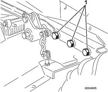
-
Grease or oil all grease fittings, pivot points, and transmission-bypass-valve pins. Wipe off any excess lubricant.
-
Lightly sand and use touch up paint on painted areas that are scratched, chipped or rusted. Repair any dents in the metal body.
-
Service the battery and cables as follows:
-
Remove the battery terminals from the battery posts.
-
Clean the battery, terminals, and posts with a wire brush and baking soda solution.
-
Coat the cable terminals and battery posts with Grafo 112X skin-over grease (Toro Part No. 505-47) or petroleum jelly to prevent corrosion.
-
Slowly recharge the battery for 24 hours every 60 days to prevent lead sulfation of the battery.
-
Preparing the Engine
-
Drain the engine oil from the oil pan and install the drain plug.
-
Change the engine oil and filter; refer to Changing the Engine Oil and Filter.
-
Fill the engine with the designated quantity of engine oil; refer to Checking the Engine-Oil Level.
-
Start the engine and run it at idle speed for 2 minutes.
-
Drain the fuel from the fuel tank, fuel lines, pump, filter, and separator. Flush the fuel tank with clean diesel fuel and connect all fuel lines.
-
Thoroughly clean and service the air-cleaner assembly.
-
Seal the air-cleaner inlet and the exhaust outlet with weatherproof masking tape.
-
Check the oil-filler cap and fuel-tank cap to ensure that they are securely in place.