Installation
Preparing the Machine
-
Park the machine on a level surface.
-
Engage the parking brake.
-
Lower the cutting units.
-
Shut off the engine, remove the key, and wait for all moving parts to stop
-
Allow the engine to cool.
Removing the Hood and Screen
-
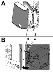
Unlatch the hood at both sides.
-
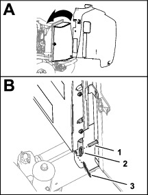
Remove the bow pin and the clevis pin that secures the hood to the pivot brackets of the machine (Figure 1).
-
Carefully lift the hood, and remove it from the machine (Figure 1).
-
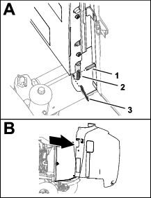
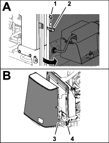
Remove the ball pin that secures the screen latch (Figure 2).
-
Unlatch the screen (Figure 2).
-
Lift the screen from the pivot pins of the radiator frame (Figure 2).
Disconnecting the Negative Battery Cable
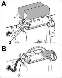
Assembling the Fuel Cooler
Parts needed for this procedure:
| Fuel hose 9.5 x 559 mm (3/8 x 22 inches) | 2 |
| Fuel cooler | 1 |
| Hose clamp | |
| Clip nut | 4 |
| Fuel-cooler bracket | 1 |
| Push-in cable tie/anchor | 2 |
| Flange capscrew (1/4 x 5/8 inch) | 4 |
| Foam strip 12.7 x 12.7 x 127 mm (1/2 x 1/2 x 5 inches) | 2 |
| Foam strip 12.7 x 12.7 x 152 mm (1/2 x 1/2 x 6 inches) | 2 |
-
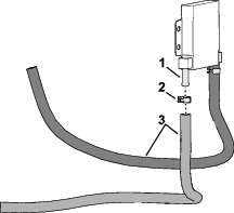
Assemble the 2 fuel hoses 9.5 x 559 mm (3/8 x 22 inches) into the fittings of the fuel cooler with the 2 spring-type hose clamps (Figure 4).
-
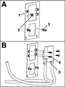
Assemble the 4 clip nuts to the holes 9.5 mm (3/8 inch) in the fuel cooler bracket (Figure 5).
-
Assemble the 2 push-in cable tie/anchors into the 2 holes 6.4 mm (1/4 inch) in the fuel-cooler bracket (Figure 5).
-
Secure the fuel cooler to the fuel-cooler bracket (Figure 5) with the 4 flange capscrews (1/4 x 5/8 inch).
-
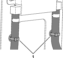
Secure the 2 fuel hoses to the fuel-cooler bracket with 2 push-in cable tie/anchor (Figure 6).
-
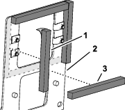
Remove the adhesive backing from the 4 foam strips (Figure 7).
-
At the other side of the fuel-cooler bracket, apply to vertical and horizontal foam strips as shown in Figure 7.
Installing the Fuel Cooler to the Radiator Bracket
Parts needed for this procedure:
| Grommet | 1 |
| Capscrew (5/16 x 5/8 inch) | 2 |
Machines with a Radiator Bracket Knock-Out Plug
-
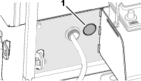
At the left side of the battery tray, remove the knock-out plug from the radiator bracket (Figure 8).
-
Remove all burrs from the hole in the bracket.
Machines without a Radiator Bracket Knock-Out Plug
-
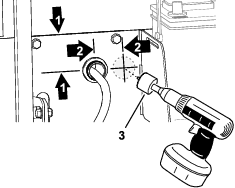
At the left side of the battery tray, measure 51 mm (2 inches) from the centerline of the hole for the battery cable and mark the radiator bracket (Figure 9).
-
Measure 64 mm (2-1/2 inches) from the top radiator bracket, and mark the bracket (Figure 9).
-
Centerpunch the radiator bracket at the intersection of the 2 marks.
-
Drill a pilot hole at the centerpunch mark.
-
Drill a 38 mm (1-1/2 inches) hole in the bracket at the pilot hole (Figure 9).
-
Remove all burrs from the hole in the bracket.
Installing the Grommet
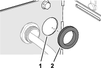
Install the grommet into the hole in the radiator bracket (Figure 10).
Assembling the Fuel Cooler to the Radiator Bracket
-
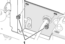
Remove the 2 Flange capscrews (5/16 x 1/2 inch) that secure the radiator to the radiator bracket (Figure 11).
Note: Discard the 2 capscrews.
-
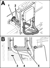
Assemble the 2 fuel hoses of the fuel cooler through the grommet in the radiator bracket (Figure 12).
-
Align the hoes in the fuel-cooler bracket with the holes in the radiator bracket (Figure 12).
-
Secure the fuel-cooler bracket to the radiator bracket (Figure 12) with the 2 capscrews (5/16 x 5/8 inch).
Connecting the Fuel-Cooler Hoses
Parts needed for this procedure:
| Barb hose connector | 2 |
| Hose clamp (worm-type) | 2 |
| Fuel hose 6.4 x 457 mm (1/4 x 18 inches) | 1 |
| Hose clamp (spring-type) | 2 |
| Cable tie | 1 |
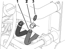
Assembling the Fuel Cooler Hose Fittings
Connecting the Fuel Tank and Fuel Cooler Hoses
-
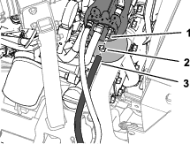
Remove the spring-type hose clamp and fuel-tank hose at the rearmost fitting of the fuel filter head (Figure 14).
Note: Retain the hose clamp.
-
Plug the end of the hose.
-
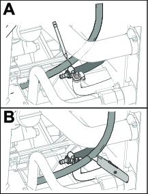
While maintaining hose routing, place the fuel tank hose next to the inboard fuel-cooler hose (Figure 15).
Note: Ensure that the fuel-tank hose routes close to the left frame rail of the machine.
-
Mark the fuel-tank hose at the barb hose fitting (Figure 15).
-
Cut the fuel-tank hose at the mark (Figure 15).
-
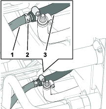
Assemble the spring-type hose clamp that you removed in step 1 onto the fuel-tank hose on the machine (Figure 16).
-
Assemble the fuel-tank hose and hose clamp onto the barb hose connector of the inboard fuel-cooler hose (Figure 16).
Connecting the Fuel Filter and Fuel Cooler Hoses
-
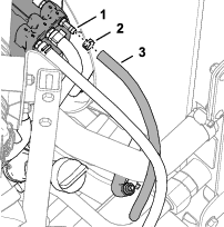
Assemble the fuel hose 6.4 x 457 mm (1/4 x 18 inches) onto the rearmost fitting of the fuel filter head with a spring-type hose clamp (Figure 17).
-
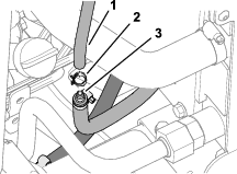
Route the other end of the fuel filter hose to the other fuel-cooler hose (Figure 18).
-
Assemble the fuel filter hose and a spring-type hose clamp onto the barb hose connector of the outboard fuel-cooler hose (Figure 18).
-
Secure the 2 fuel-cooler hoses together with a cable tie (Figure 19).
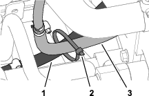
Completing the Kit Installation
Connecting the Negative Battery Cable
-
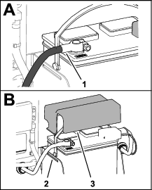
Clean any corrosion on the negative battery cable clamp and the battery post.
-
Assemble the clamp of the negative battery cable onto the battery post, and tighten the T-bolt and nut of the clamp (Figure 20).
-
Apply a thin coat of battery terminal protector to the battery-cable clamp.
-
Assemble the battery cover over the battery, aligning the tabs of the cover into the slots in the battery tray (Figure 20).
Purging Air from the Fuel System
-
Rotate the ignition key to the RUN or ON position.
-
Allow the electric fuel pump to run for 10 seconds.
-
Rotate the ignition key to the STOP position.
-
Wait for 35 to 40 seconds.
-
Repeat steps 1 through 4 again 2 more times.
-
Start the engine, and preform the steps in Checking for Fuel Leaks.
Checking for Fuel Leaks
-
Check the fuel hoses, fittings, and fuel cooler for leaks.
Important: Repair all fuel leaks.
-
Shut off the engine and remove the key.