Installation
Preparing to Install the Rear Work Light Kit
-
Park the machine on a level surface, shut off the engine, set the parking brake, and remove the key from the ignition.
-
Remove the battery cover as follows:
Warning
Battery terminals or metal tools could short against metal tractor components, causing sparks. Sparks can cause the battery gasses to explode, resulting in personal injury.
-
When removing or installing the battery, do not allow the battery terminals to touch any metal parts of the tractor.
-
Do not allow metal tools to short between the battery terminals and metal parts of the tractor.
-
Multi Pro 5800: Remove the battery strap from the battery cover and battery box, and remove the cover; refer to the Operator’s Manual for the Multi Pro 5800 machine.
-
Multi Pro WM: Squeeze the sides of the battery cover and remove the cover from the battery tray; refer to the Operator’s Manual for the Multi Pro WM machine.
-
-
Multi Pro 1750: Unlatch the operator's seat and tilt the seat forward; refer to the Operator’s Manual for the Multi Pro 1750 machine.
-
Disconnect the negative (black—ground) cable from the battery post; refer to the Operator’s Manual for your machine.
Warning
Incorrect battery cable routing could damage the machine and cables, causing sparks. Sparks can cause the battery gasses to explode, resulting in personal injury.
-
Always disconnect the negative (black) battery cable before disconnecting the positive (red) cable.
-
Always connect the positive (red) battery cable before connecting the negative (black) cable.
-
-
Multi Pro 1750 or Multi Pro WM: Slide the insulated cover over the clamp of the positive battery cable; refer to the Operator’s Manual for the Multi Pro 1750 or Multi Pro WM machines.
-
Disconnect the positive battery cable from the battery; refer to the Operator’s Manual for your machine.
Assembling the LED Lights to the Brackets
Parts needed for this procedure:
| LED light | 2 |
| Light-mount bracket | 2 |
| Carriage bolt (5/16 x 1 inch) | 2 |
| Flange locknut (5/16 inch) | 2 |
-
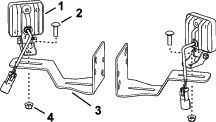
Assemble the LED light to the light-mount bracket with the carriage bolt (5/16 x 1 inch) and flange locknut (5/16 inch) as shown in Figure 1.
-
Repeat step 1 for the other light and bracket.
Assembling the Switches and the Wire Harness
Parts needed for this procedure:
| Switch bracket | 1 |
| Rocker switch | 2 |
| Wire harness | 1 |
-
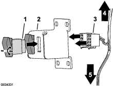
Align the rocker switch to the opening in the switch bracket (Figure 2).
Note: Align the pivot point of the rocker switch above the middle of the switch.
-
Insert the switch into the opening until the latch on the switch snaps securely (Figure 2).
-
Repeat steps 1 and 2 for the other rocker switch.
-
Connect the 8-socket connectors of the wire harness to the 8-pin connectors of the rocker switches (Figure 2).
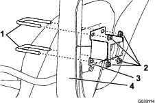
Removing the Left Seat Base and Fender (Multi Pro 1750)
-
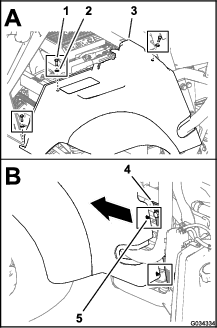
Remove the 3 bolts (5/16 x 1 inch) and 3 washers (5/16 inch) that secure the left seat base and fender to the chassis of the machine (Figure 3).
-
Move the seat base and fender forward to unseat the 2 plastic-clip anchors of the seat base from the 2 holes 6.4 mm (1/4 inch) in the channel for the ROPS at the left side of the machine (Figure 3).
Note: Retain the plastic-clip anchors for installation in Installing the Left Fender (Multi Pro 1750).
-
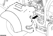
Lift the seat base and fender away from the parking brake and off the machine (Figure 4).
Note: Release the parking brake handle if necessary to provide clearance for the seat base; set the parking brake after the seat base and fender are removed from the machine.
Installing the Rear Work Lights and Light Switches to the Machine
Parts needed for this procedure:
| U-bolt (3/8 x 3-1/2 x 2-13/16 inches) | 2 |
| U-bolt (3/8 x 2-15/16 x 3-1/2 inches) | 4 |
| Flange locknut | 8 |
| U-bolt (3/8 x 2-7/16 x 2-13/16) | 2 |
Assembling the Lights for the ROPS Tube (Multi-Pro 1750)
-
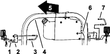
At the left side of the ROPS, remove the U-bolt (3/8 x 3-1/2 x 2-13/16 inches) and flange locknut that secures the mount for the fresh-water tank to the ROPS tube (Figure 5).
-
Assemble the LED light and bracket to the ROPS tube and fresh water-tank mount as shown in Figure 5 with the U-bolt (3/8 x 3-1/2 x 2-13/16 inches) and the flange locknut (3/8 inch) that you removed in step 1.
Note: Use the diagonal-mounting holes in the light bracket.
-
At the other side of the ROPS tube, assemble the LED light and bracket to the ROPS tube with a U-bolt (3/8 x 3-1/2 x 2-13/16 inches) and a flange locknut (3/8 inch) from the rear work light kit (Figure 5).
-
Torque the locknuts to 37 to 45 N∙m (27 to 33 ft-lb).
Assembling the Lights for the ROPS Tube (Multi-Pro 5800)
-
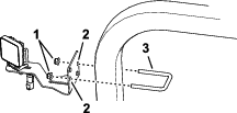
Assemble the LED light and bracket to the ROPS tube with the U-bolt (3/8 x 2-7/16 x 2-13/16) and flange locknut as shown in Figure 6.
Note: Use the perpendicular-mounting holes in the light bracket.
-
Repeat step 1 for the LED light and bracket at the other side of the ROPS tube.
-
Torque the locknuts to 37 to 45 N∙m (27 to 33 ft-lb).
Assembling the Lights to the 4-Post ROPS Frame (Multi-Pro WM)
-
Assemble the LED light and bracket to the rear ROPS tube with the U-bolt (3/8 x 3-1/2 x 2-13/16 inches) and flange locknut (3/8 inch) as shown in Figure 7.
Note: Use the diagonal-mounting holes in the light bracket.
-
Repeat step 1 for the LED light and bracket at the other side of the ROPS tube.
-
Torque the locknuts to 37 to 45 N∙m (27 to 33 ft-lb).
Installing the Light Switches to the Machine
-
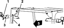
For the Multi Pro 1750 and Multi Pro WM machines, install the switch bracket to the front side of the ROPS assembly using 2 U-bolts (3/8 x 2-7/16 x 2-13/16 inches) and 2 flange locknuts (3/8 inch) as shown in Figure 8.
-
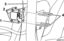
For the Multi Pro 5800 machine, install the switch bracket to the back side of the ROPS assembly using 2 U-bolts (3/8 x 2-15/16 x 3-1/2 inches) and 4 flange locknuts (3/8 inch) as shown in Figure 9.
Routing and Connecting the Wire Harness
Parts needed for this procedure:
| Cable tie | 6 |
Multi Pro 1750 Machine
-
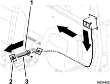
At the switches, route the branch of the wire harness with the 2-socket connector up and across the back of the horizontal ROPS tube as shown in Figure 10.
Note: Bundle the excess harness at the middle of the ROPS and secure the harness bundle with a cable tie as shown in Figure 10.

-
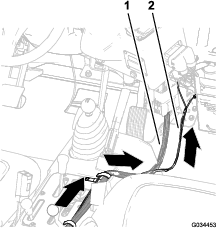
At the light switches, route the branch of the wire harness with the socket terminal and ring terminal down and forward as shown in Figure 11 and Figure 12.
Important: Provide clearance between the wire harness and the sprocket and belt of the engine.
Note: Route the wire harness for the rear work light kit along the wire harness of the machine.
-
Secure the wire harness for the rear work light kit to the ROPS tube, upper, the front-frame tube of the machine, and the wire harness for the machine with cable ties as shown in Figure 10, Figure 11, and Figure 12.
Note: Bundle the excess harness at the upper, front-frame tube and secure the harness bundle with a cable tie as shown in Figure 11.
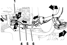
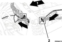
Multi Pro 5800 Machine
-
At the switches, route the branch of the wire harness with the 2-socket connector up and across the back of the horizontal ROPS tube as shown in Figure 13.

-
At the light switches, route the branch of the wire harness with the socket terminal and ring terminal down and forward as shown in Figure 14 and Figure 15.
Important: Provide clearance between the wire harness and the exhaust pipe of the engine.
Note: Route the wire harness for the rear work light kit along the wire harness of the machine (Figure 15).

-
Secure the wire harness to the ROPS tube and support for the seat base with cable ties as shown in Figure 13, Figure 14, and Figure 15.
Note: Bundle the excess harness at the support for the seat base and secure the harness bundle with a cable tie as shown in Figure 15.
Multi Pro WM Machine
-
At the switches, route the branch of the wire harness with the 2-socket connector up and across the back of the horizontal ROPS tube as shown in Figure 16.

-
At the light switches, route the branch of the wire harness with the socket terminal and ring terminal down and across the back of the operator’s seat as shown in Figure 17.
-
At the center console, route the wire harness for the rear work light kit along the wire harness for the sprayer and forward toward the fuse block (Figure 17 and Figure 18).
-
Secure the wire harness for the rear work light kit to the wire harness for the sprayer with cable ties as shown in Figure 16 and Figure 17.
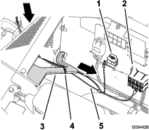
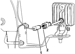
Connecting the Wire Harness to the LED Lights
Connecting the Wire Harness to the Fuse Block
Parts needed for this procedure:
| Fuse block | 1 |
| 10A fuse | 1 |
-
Connect the wire harness to the fuse block and grounding wire to the grounding block (Figure 20).
Note: Multi Pro 1750 and Multi Pro 5800 machines: The fuse block and grounding block are located under the seat of the machine.Multi Pro WM machine: The fuse block and grounding block are located under the dash of the machine.

-
If a circuit is not available in the fuse block of the machine, install the auxiliary-fuse block (Figure 21) onto the fuse block of the machine.
-
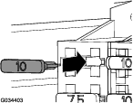
Install the fuse (10 A) into the fuse-block socket for the LED lights (Figure 22).
Installing the Left Fender (Multi Pro 1750)
-
Align the opening in the top of the seat base with the parking-brake lever.
Note: Release the parking brake handle if necessary to provide clearance for the seat base.
-
Align 2 holes in the seat base where you removed the plastic-clip anchors in step 2 of Removing the Left Seat Base and Fender (Multi Pro 1750) with the 2 holes 6.4 mm (1/4 inch) in the channel for the ROPS (Figure 3).
-
Install the 2 plastic-clip anchors through the 2 holes in the seat base and the 2 holes in the channel for the ROPS; refer to Figure 3 of Removing the Left Seat Base and Fender (Multi Pro 1750).
-
Assemble seat base to the chassis of the machine with the 3 bolts (5/16 x 1 inch) and 2 washers (5/16 inch) that you removed in step 1 of Removing the Left Seat Base and Fender (Multi Pro 1750).
-
Torque the bolts to 1017 to 1355 N∙m (90 to 120 in-lb).
-
If you released the parking brake, set the parking brake.
Finishing the Rear Work Light Kit Installation
Warning
Incorrect battery cable routing could damage the machine and cables, causing sparks. Sparks can cause the battery gasses to explode, resulting in personal injury.
-
Always disconnect the negative (black) battery cable before disconnecting the positive (red) cable.
-
Always connect the positive (red) battery cable before connecting the negative (black) cable.
-
Connect the positive battery cable to the positive post of the battery; refer to the Operator’s Manual for your machine.
-
Connect the negative battery cable to the negative post of the battery; refer to the Operator’s Manual for your machine.
-
Multi Pro 1750 or Multi Pro WM: Slide the insulated cover over the clamp of the positive battery cable; refer to the Operator’s Manual for the Multi Pro 1750 or Multi Pro WM machines.
-
Install the battery cover as follows:
-
Multi Pro 5800: Align the battery cover to the battery box and secure the cover with the battery strap; refer to the Operator’s Manual for the Multi Pro 5800 machine.
-
Multi Pro WM: Squeeze the sides of the battery cover, align the tabs of the battery cover to the slots in the battery tray, and release the cover; refer to the Operator’s Manual for the Multi Pro WM machine.
-
-
Multi Pro 1750: Rotate the seat back and down until the seat latches securely into position; refer to the Operator’s Manual for the Multi Pro 1750 machine.
Multi Pro 5800: Rotate the operator’s seat back and down until aligns to the seat box of the chassis; refer to the Operator’s Manual for the Multi Pro 5800 machine.
Checking the LED Lights
-
Press the rocker switches up to the ON position.
Note: The LED lights will illuminate.
-
If the light(s) are not illuminated when the rocker switches are in the ON position, the switches are misaligned upside down in the bracket; perform the following:
-
Note the switch that is misaligned upside down.
-
Disconnect the battery; refer to Preparing to Install the Rear Work Light Kit.
-
At the switch bracket, disconnect the 8-socket connector of the wiring harness from the misaligned rocker switch; refer to Figure 2 of Assembling the Switches and the Wire Harness.
-
Remove the rocker switch from the switch bracket; refer to Figure 2 of Assembling the Switches and the Wire Harness.
-
Rotate the rocker switch 180° and insert it into the switch bracket until the latch on the switch snaps securely.
-
Connect the 8-socket connector of the wiring harness to the 8-pin connector of the rocker switch; refer to Figure 2 of Assembling the Switches and the Wire Harness.
-
Connect the battery; refer to Finishing the Rear Work Light Kit Installation.
-
-
If the left light switch is controlling the wrong LED light, perform the following:
-
Disconnect the battery; refer to Preparing to Install the Rear Work Light Kit.
-
At the switch bracket, disconnect the 8-socket connectors of the wiring harness from rocker switches; refer to Figure 2 of Assembling the Switches and the Wire Harness.
-
Exchange the positions of the 8-socket connectors at the rocker switches.
-
Connect the 8-socket connectors of the wiring harness to the 8-pin connectors of the rocker switches; refer to Figure 2 of Assembling the Switches and the Wire Harness.
-
Connect the battery; refer to Finishing the Rear Work Light Kit Installation.
-
-
Press the rocker switches up to the ON position to illuminate the LED lights.
-
Press the rocker switches down to the OFF position to shut off the LED lights.