Installation
Preparing the Machine
-
Park the machine on a level surface, remove any attachment, engage the parking brake, raise the loader arms, and install the cylinder locks.
-
Shut off the engine and remove the key.
-
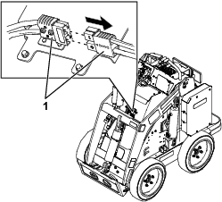
Remove the hood.
-
Separate the 2 main-power connectors.
-
Remove the rear cover.
Installing the Fuse Bracket
Parts needed for this procedure:
| Fuse bracket | 1 |
-
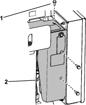
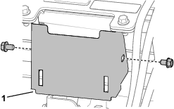
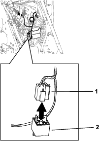
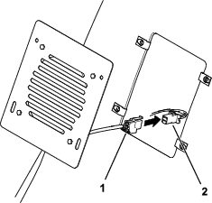
Remove the fuse holder from the bracket.
-
Remove the existing fuse bracket.
-
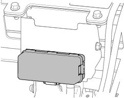
Using the bolts you removed, install the new fuse bracket.
-
Install the fuse cover to the bracket.
Routing the Wire Harness
Parts needed for this procedure:
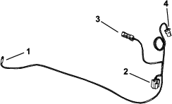
| Wire harness | 1 |
| Relay | 1 |
| Fan | 1 |
| Cable tie | 3 |
Note: Do not connect the wire harness to the fan in this procedure.
-
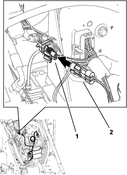
Connect the wire harness (P04) to the control port connector on the machine wire harness.
Note: The control port connector is cable tied to the wire harness, near the controller.
-
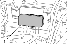
Install the relay to the relay connector.
-
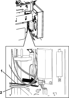
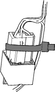
Route the wire harness along the battery cable to the rear, right side of the machine and into the mount bracket.
-
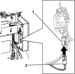
Remove the cap from the accessory connector on the machine wire harness. Plug the accessory connector (P03) into the connector.
Note: The accessory connector on the machine wire harness is cable tied to the harness near the fuse.
-
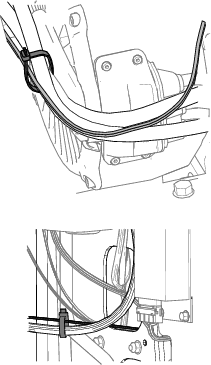
Use 2 cable ties to secure the wire harness to the battery cable.
-
Use another cable tie to secure the relay connector to the wire harness.
Trimming the Hood
Parts needed for this procedure:
| Clip nut | 4 |
-
Remove the front cover from the hood. Retain the bolts.

-
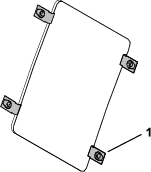
Remove and discard the clips nuts.
-
Cut out the template at the end of this publication.
-
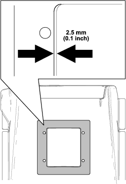
Align the holes on the template with the holes in the hood.
-
Trace the inside of the template on the hood.
Note: This expands the left and right sides of the hood opening 2.5 mm (0.1 inch).
-
Use a jigsaw to cut the hood and expand the opening to the traced lines. Smooth any rough edges.
Warning
Using a power tool without wearing eye protection may allow debris to enter the eye, causing personal injury.
When using power tools, always wear eye protection.
-
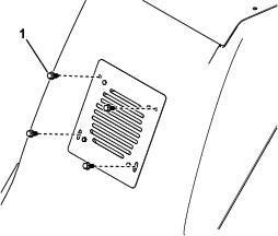
Install the new clip nuts (Figure 15).
Installing the Fan
Parts needed for this procedure:
| Fan cover | 1 |
| Bolt | 4 |
| Nut | 4 |
| Cable tie | 1 |
-
Install the hood.
-
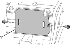
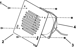
Install the fan cover to the fan.
-
Connect the fan connector (P01) from the wire harness to the fan.
-
Use the remaining cable tie to reduce the excess slack on the wire harness.
Installing the Covers
-
Install the rear cover.
-
Connect the 2 main-power connectors.
-
Secure the fan to the hood using the retained bolts from the front cover.
Updating the Software
Parts needed for this procedure:
| Diagnostic cable (sold separately) | 1 |
The following procedure must be performed by an Authorized Service Dealer. The fan will not operate without the software update.
Update the machine software using the Toro DIAG software and diagnostic cable (part number 115-1944, sold separately).
Note: Download the Toro DIAG software package and its Software Guide from Gateway.