Safety
Safety and Instructional Decals
 |
Safety decals and instructions are easily visible to the operator and are located near any area of potential danger. Replace any decal that is damaged or lost. |
Installation
Preparing the Machine
-
Park the machine on a level surface.
-
Engage the parking brake.
-
Shut off the engine and remove the key.
-
Disconnect the negative ( - ) battery cable from the battery.
Installing the Brackets and Light Assemblies
Parts needed for this procedure:
| Light assembly | 2 |
| Left bracket | 1 |
| Right bracket | 1 |
| U-bolt | 2 |
| Nuts | 4 |
-
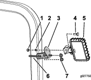
Install a bracket onto each side of the ROPS using a U-bolt and 2 nuts as shown in Figure 1.
-
Install the light assembly as shown in Figure 1.
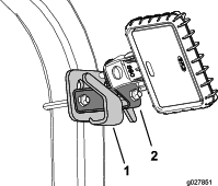
If your machine is equipped with a bimini shade, use the U-bolt from this kit and install the light assembly as shown in Figure 2 .
For Greensmaster 3250 models with a round tube ROPS, the bracket is not needed. Install the light assembly directly onto the ROPS tabs.
Installing the Wiring Harness
Parts needed for this procedure:
| Wiring harness | 1 |
| Cable ties (14.5 inch) | 10 |
| Cable ties (7.25 inch) | 2 |
| Wiring harness adapter (Greensmaster 3150 and 3250 models prior to 2015 only) | 1 |
| Splice, 12-10 awg (Greensmaster 3150 models prior to 2015 only) | 1 |
| Splice, 16-14 awg (Greensmaster 3150 and 3250 models prior to 2015 only) | 2 |
Ensure that the wiring harness is routed away from any hot, sharp, or moving parts.
-
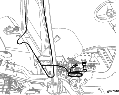
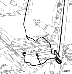
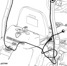
Route the wiring harness along the ROPS and under the seat as shown in Figure 3, Figure 4, or Figure 5.
-
Secure the wiring harness to the ROPS, behind the seat, and under the control panel with the 10 (14.5 inch) cable ties.
Note: If you are not using the rear light kit, the branch of the harness with the rear light connector (labeled REAR WORK LIGHT) can be curled up and tied down near the seat.
-
Secure the wiring harness near the light assemblies with the 2 (7.25 inch) cable ties into the available hole on the light bracket (Figure 1).
-
Plug the light kit wiring harness into the terminal on the main wiring harness.
For the Greensmaster 3150 models built before 2015:
Contact an authorized Toro distributor to see the electrical schematics to locate the terminals to splice.
-
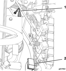
Route the light kit harness from the light assemblies on the ROPS to the light kit terminals (J13 and J14) on the machine harness, located behind the seat (Figure 6).
-
Remove the connector P01 and switch P02 from the light kit harness and cut the harness to size.
-
Tape the end of the yellow wire on the light kit harness.
-
Connect the single black wire from the light kit harness to the black wire, that was previously leading to terminal J13, using the splice connector 16-14 awg.
-
Connect the 2 blue wires from the light kit harness to the white wire, that was previously leading to terminal J14, using splice connector 12-10 awg.
For the Greensmaster 3250 models built before 2015:
Contact an authorized Toro distributor to see the electrical schematics to locate the terminals to splice.
-
Splice the black wire, that was previously leading to connector J6, to the black wire of the light kit adapter using splice connector 16-14 awg.
-
Splice the gray wire with the black stripe, that was previously leading to connector J7 on the existing harness, to the white wire on the light kit adapter using splice 16-14 awg.
Installing the Switch, Fuse, and Decal (Greensmaster 3250 only)
Parts needed for this procedure:
| Switch | 1 |
| Fuse | 1 |
| Decal (Greensmaster 3250 build before 2015 only) | 1 |
Installing the Switch and Fuse for the Greensmaster 3150
-
Remove the 5 bolts securing the console shroud and remove the shroud.
-
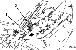
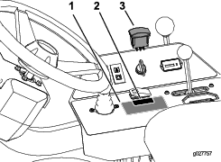
Remove the plastic plug and install the switch as shown in Figure 7.
-
Connect the switch to the wiring harness.
-
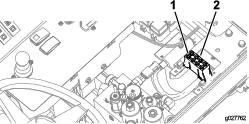
Install the fuse into the fuse block (Figure 8).
Important: Ensure that the corresponding wire to the open fuse position is White.
-
Install the console shroud.
-
Connect the negative battery cable.
For Greensmaster 3150 models built before 2015: follow the instructions above, but use the existing switch on the control panel. This switch is used to test the leak detector and operate the light kit.
Installing the Switch, Fuse, and Decal for the Greensmaster 3250
-
Remove the 3 bolts securing the console shroud and remove the shroud.
-
Remove the plastic plug and install the switch as shown in Figure 9.
-
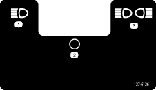
For models built before 2015: Apply the decal onto the control panel as shown in Figure 9.
-
Install the fuse into the fuse block (Figure 8).
Important: Ensure that the corresponding wire to the open fuse position is Green with a white stripe.
-
Connect the switch to the wiring harness.
-
Install the console shroud.
-
Connect the negative battery cable.
Installing the Switch for the Greensmaster TriFlex
-
Remove the 7 hex bolts securing the console cover in place and remove the console cover.
-
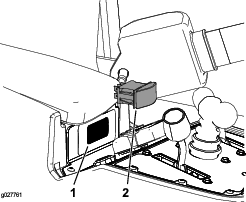
From inside the console, press the plug out of the hole (Figure 10).
-
Press the rocker switch into the console mounting hole as shown in Figure 10.
-
Connect the switch to the wiring harness.
-
Install the console shroud.
-
Connect the negative battery cable.
A fuse is already in place for the TriFlex models. The fuse included in this kit can be used as a replacement fuse as needed.
Installing the Rear-Light Kit (Optional)
Parts needed for this procedure:
| Rear-light kit (optional) | 1 |
Install the rear-light kit assemblies as shown in Figure 11.
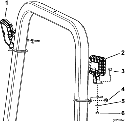
Remove the plastic cover from the rear light jumper, connector P05, on the light kit harness and connect it to the rear light assembly.
Note: Greensmaster 3150 models built prior to 2015 and Greensmaster 3250 models that have a rounded ROPS cannot use this optional kit.
Operation
Operating the Light Switch
Note: To adjust the lights, you can loosen the mounting hardware, aim the lights as desired, and tighten the hardware to secure the lights in the newly adjusted position.
The light switch has 3 positions; refer to Figure 12.
