
Maintenance
Recommended Maintenance Schedule(s)
| Maintenance Service Interval | Maintenance Procedure |
|---|---|
| After the first 10 hours |
|
| Before each use or daily |
|
| Yearly |
|
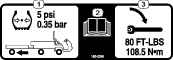
Checking the Tire Air Pressure
| Maintenance Service Interval | Maintenance Procedure |
|---|---|
| Before each use or daily |
|
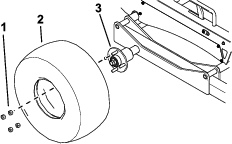
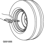
Tire air pressure specification: 34 kPa (5 psi)
Check the air pressure in the tires (Figure 32). Add or remove air as needed to set the air pressure in the tires to the tire air-pressure specification.
Checking the Wheel Bearings for Freeplay
| Maintenance Service Interval | Maintenance Procedure |
|---|---|
| Yearly |
|
-
Remove any machines that may be stored on the trailer.
-
Use a jack to raise the trailer and place jack stands under the trailer.
-
Check each wheel for excessive freeplay (i.e., free movement of the tire and hub assembly).
If you detect excessive freeplay, contact to your authorized Toro distributor.
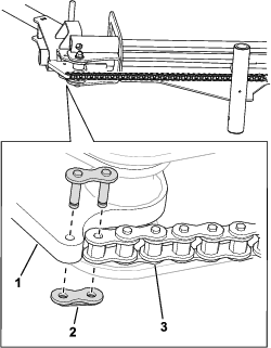
Lubricating the Chains
| Maintenance Service Interval | Maintenance Procedure |
|---|---|
| Yearly |
|
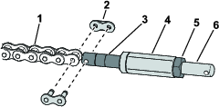
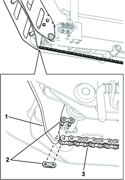
Apply general-purpose grease to each chain.
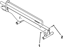
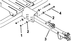
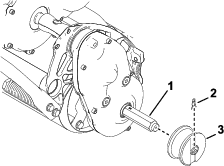
Checking the Torque of the Roller-Mount Fasteners
| Maintenance Service Interval | Maintenance Procedure |
|---|---|
| Yearly |
|
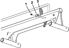
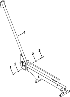
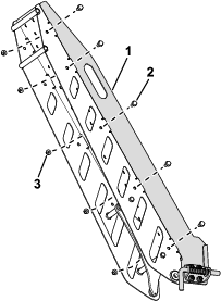
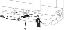
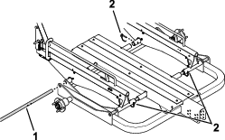
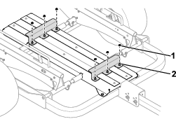
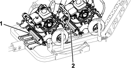
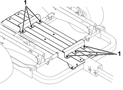
Torque the roller-mount fasteners (Figure 33) to 79 N∙m (700 in-lb).
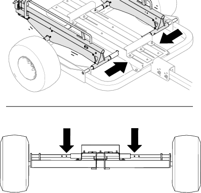
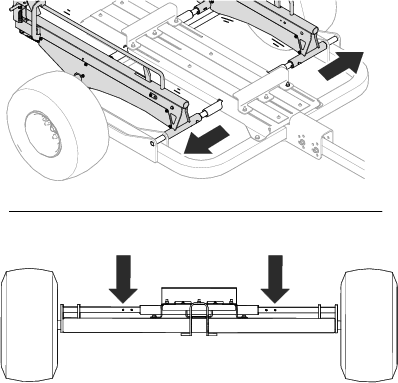
Checking the Torque of the Wheel Lug Nuts
| Maintenance Service Interval | Maintenance Procedure |
|---|---|
| After the first 10 hours |
|
Torque specification: 108 N⋅m (80 ft-lb)
Check the torque of the wheel lug nuts each time you install the wheels and after the first 10 hours of operation.
Torque the wheel lug nuts in the pattern as shown in Figure 34 to the specified torque.
Warning
Failure to maintain proper torque could result in failure or loss of wheel and could result in personal injury.
Torque the wheel lug nuts to the specified torque.

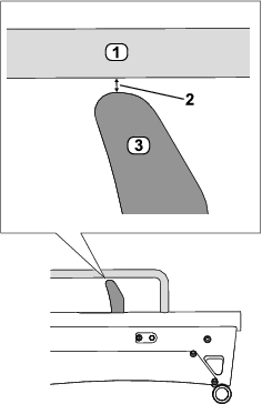
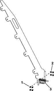
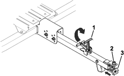
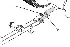
Checking the Stop Gap
| Maintenance Service Interval | Maintenance Procedure |
|---|---|
| Yearly |
|
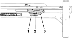
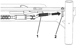
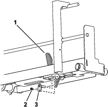
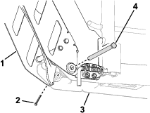
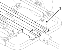
With the ramps secured in the raised position, check the gap measurement between the stop and bottom of the rail.
The appropriate measurement should be 2.5 mm (0.1 inch) as shown in Figure 35. If you observe a different measurement, adjust the turnbuckle and jam nut until you reach the appropriate measurement.